Computherm WPR-100GC User manual

COMPUTHERM
WPR-100GC
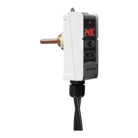
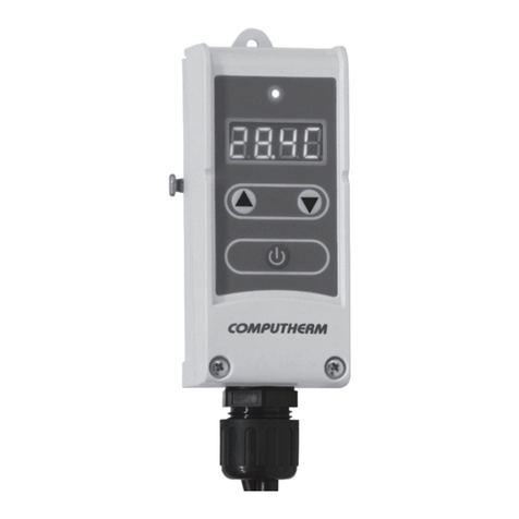
Pump controller with wired temperature sensor
Operating Instructions

- 2 -
GENERAL DESCRIPTION OF THE PUMP CONTROLLER
The pump controller uses its wired heat sensor and the pipe sleeve immersed into the pipeline/boiler
to detect the temperature of the standing or owing medium in it, switches the 230 V at the output at
the set temperature. By the pre-mounted wires any circulating pump with a voltage of 230 V or other
electrical appliance within the load capacity limits can be easily controlled.
The pump controller is responsible for turning the pump on and o at the set and measured temper-
ature, so it only operates when it is necessary. Intermittent operation saves signicant energy and
increases pump life and reduces operating costs. Its digital display allows easier and more accurate
temperature measurement and adjustment than simple, traditional pipe thermostats, and makes it
easier to change modes and settings.

- 3 -
The controller has several modes that makes it possible to use
for manual and temperature-based control of the circulating
pumps in heating and cooling systems. In case of tempera-
ture-based control the connected pump switches on/o ac-
cording to set temperature and the switching sensitivity.
1. LOCATION OF THE DEVICE
It is recommended to place the pump controller near the heat-
ing / cooling pipe or boiler on which the control is based so
that it is as close as possible to a maximum of 1.5 m from the
pump to be controlled and the 230 V supply and at a maximum
distance of 0.9 m from the selected temperature measuring
point. Do not use a wet, chemically aggressive or dusty en-
vironment.

- 4 -
2. INSTALLATION OF THE DEVICE
Warning! The device must be installed/put into service by a competent person! Before commis-
sioning make sure that neither the thermostat nor the appliance you want to connect to is con-
nected to the 230 V mains. Modifying the device can cause electric shock or product failure.
Caution! The voltage 230 V is displayed when the output of the appliance is switched on. Make
sure that the wires are properly connected and that that there is no risk of electric shock or short
circuit!
Connect your device as follows:
● After placing the included immersion sleeve, place the heat sensor probe of the pump con-
troller in it.
● Connect the 3 wires to the pump you want to control. The marking of the wires are based on
the EU standard: brown - phase, blue - zero, green-yellow - earth.
● Connect the pump controller to the 230 V mains using the pre-mounted connector

- 5 -
mosta
8.8.8.8
230 V AC, 50 Hz 230 V AC, 50 Hz
szivattyú
szivattyúvezérlő
Warning! Always take into account the loadability of the controller relay when connecting
(10 A (3 Inductive load)) and follow the instructions of the manufacturer of the pump which you
would like to control.
Pump controller
Pump

- 6 -
3. BASIC SETTINGS
After the appliance is connected, the measured temperature is shown on the display when the appli-
ance is switched on. You can change the default settings as written below.
3.1. Change the mode of control (F1/F2/F3)
The device can be used in three modes, which are detailed as follows:
- F1 (factory default) - Control of a heating system’s circulating pump: the output is turned on
if the measured temperature is higher than the set temperature. The switching sensitivity is taken into
account when switching.
- F2 - Control of a cooling system’s circulating pump: the output is turned on
if the measured temperature is lower than the set temperature. The switching sensitivity is taken into
account when switching.
- F3 - Manual mode: regardless of the measured temperature, the output is permanently switched
on/o according to the setting.
To switch between modes, press and hold the button for 4 seconds. The currently selected F1, F2,
or F3 value is displayed.

- 7 -
It is possible to switch between the modes By pressing the or buttons. To save this setting, wait
after the last key press approx. 6 seconds. The display will then return to the state (on/o) from which
you entered the mode selection menu after a few ashes and the settings will be saved.
3.2. Selection of switching sensitivity
The pump controller in modes F1 and F2 switches the output according to the measured temperature
and switching sensitivity. In these modes, it is possible to change the switching sensitivity. By select-
ing this value, you can specify how much the device switches the connected pump on/o below/above
the set temperature. The lower this value is, the more constant the temperature of the circulating uid
will be. The switching sensitivity can be set between ± 0.1 °C and ± 15.0 °C (in 0.1 °C steps). Except
some special cases, we recommend setting ± 1.0 °C (factory default setting). See Chapter 4 for more
information on switching sensitivity.
To change the switching sensitivity, when the pump control is switched ON, in F1 or F2 mode, press
and hold the button for approximately 2 seconds until the „d 1.0” (factory default) appears on the
display. By pressing the and buttons you can change this value in increments of 0,1 °C within the
range of ±0,1 °C and ±15,0 °C.
To exit and save the setting, wait for approx. 4 seconds. The device then returns to its default state.

- 8 -
3.3. Pump protection function
ATTENTION! When using the pump protection function, it is recommended that the part of the heat-
ing system in which the pump to be controlled is installed has a heating circuit during the heating-free
period in which the heating medium can ow freely at all times. Otherwise, using the pump protection
function may damage the pump.
The pump protection function of the pump controller protects the pump from sticking during long pe-
riods of non-use. When the function is on, the output will turn on every 5 days for 15 seconds if the
output has not been turned on in the last 5 days. During this time, „ ” will appear on the display
instead of the measured temperature.
To activate/deactivate the pump protection function, rst switch o the appliance by pressing the
button once (the display switches o), then press and hold the button for 3 seconds. „POFF” (factory
default setting) will appear on the display, indicating that the function is switched OFF. Press or
to change between ON/OFF states. The ON status of the function is indicated by „ ”. To save the
setting and exit the function setting, wait approx. 7 seconds. The device is then switched OFF.

- 9 -
3.4. Frost protection function
ATTENTION! The use of the frost protection function is only recommended if there is a heating circuit
in the heating system in which the pump to be controlled is installed, even during the heating-free
period, in which the heating medium can ow freely at all times. Otherwise, using the frost protection
function may damage the pump.
The frost protection function of the pump controller, when switched ON, switches on the pump when
the measured temperature drops below 5 °C and leaves it ON until the measured temperature reach-
es 5 °C again to protect the pump and the heating system. During this time, the display alternates
between „ ” and the measured temperature. When the frost protection function is activated, it op-
erates in all three modes (F1, F2 and F3).
To switch the frost protection function ON/OFF, rst switch o the appliance by pressing the button
once (it switches OFF the display), then press and hold the button for 3 seconds. „FPOF” (factory
default setting) will appear on the display, indicating that the function is deactivated. Press or
to change between ON/OFF states. The ON status of the function is indicated by „ ”. To save the
setting and exit the function setting, wait approx. 7 seconds. The device is then switched OFF.

- 10 -
4. OPERATION OF THE INSTALLED PUMP CONTROLLER
In operating modes F1 and F2, the pump controller controls the device connected to it (eg. a pump)
based on the temperature it measures and the set temperature, taking into account the set switching
sensitivity (factory default ±1.0 °C). This means that if the pump controller is set to F1 mode (heat-
ing system circulating pump control) and 40 °C, the 230 V will appear at the controller’s output at a
temperature above 41.0 °C at a switching sensitivity of ±1.0 °C (the pump connected to it switches
ON) and at temperatures below 39.0 °C the output switches OFF (the pump connected to it switches
OFF). In F2 mode, the output switches exactly the opposite way. You can adjust the set temperature
with the and buttons.
In F3 mode, the output is permanently ON/OFF according to the setting, regardless of the measured
temperature in F3 mode. You can change between ON and OFF by using the and keys.
During normal operation, the device always displays the currently measured temperature on its dis-
play in all three operating modes. The device indicates the ON/OFF status of its output by means of
the LED above the display.

- 11 -
TECHNICAL DATA:
Adjustable temperature range: 5-90 °C (0.1 °C)
Temperature measurement range: -19 to 99 °C (in 0.1 °C increments)
Switching sensitivity: ±0.1 to 15.0 °C (in of 0,1 °C increments)
Temperature measurement accuracy: ±1,0 °C
Power supply: 230 V AC; 50 Hz
Output voltage: 230 V AC; 50 Hz
Loadability: max. 10 A (3 Inductive load)
Environmental protection: IP40
Immersion sleeve connector size: G=1/2”; Ø8x60 mm
Length of heat sensor wire: approx. 0.9 m
Length of wires for electrical connection: approx. 1.5 m
Max. ambient temperature: 80 °C (probe 100 °C)
Storage temperature: -10 °C....+80 °C
Operating humidity: 5 % to 90 % without condensation

The
COMPUTHERM
WPR-100GC type pump controller complies with the requirements of
standards EMC 2014/30/EU, LVD 2014/35/EU and RoHS 2011/65/EU.
Manufacturer: QUANTRAX Kft.
H-6726 Szeged, Fülemüle u. 34.
Telefon: +36 62 424 133 • Fax: +36 62 424 672
Web: www.quantrax.hu • www.computherm.info
Country of origin: China
Table of contents
Other Computherm Controllers manuals
Popular Controllers manuals by other brands

Franklin Electric
Franklin Electric SubDrive15 Connect N3R install guide

Savant
Savant SmartControl 12 Quick reference guide

Edgewater Networks
Edgewater Networks EdgeMarc 4570 quick start guide

Symondo
Symondo Controller Installation and operating instruction

Outline
Outline Genius 6 operating manual

EUROSTER
EUROSTER 11W Installation and operation manual