Comunello CU-230V-1M User manual

CU - 230V - 1M
INSTALLATION AND USER’S MANUAL
comunello.com
Control units
ISTRUZIONI D’USO E DI INSTALLAZIONE
INSTALLATIONS-UND GEBRAUCHSANLEITUNG
INSTRUCIONS D’UTILISATION ET D’INSTALLATION
INSTRUCCIONES DE USO Y DE INSTALACION
ИНСТРУКЦИЯ ПО МОНТАЖУ Cod. 91300172 - Rev. 04 - 06.09.18

2COMUNELLO ®Copyright 2016 - All right reserved
MENÙ LIST
ID LED
L1 FOTOTEST ON OFF
L2 PEDESTRIAN TIME ON OFF
L3 DECELERATION OFF ON
L4 ELEC BRAKE ON OFF
L5 RELEASE STROKE ON OFF
L6 SLAM LOCK ON OFF
L7 COURTESY LIGHT ON OFF
LEV MENÙ 1 FLASH
ID LED
L1 SOFT STOP ON OFF
L2 SOFT START ON OFF
L3 SAFE 1 IN OPEN ON OFF
L4 HOLD-TO-RUN ON OFF
L5 FOLLOW ME ON OFF
L6 PAUSE FLASHING ON OFF
L7 ALWAYS CLOSE ON OFF
LEV LEV LONG FLASHING
ID LED
L1 DIR Left Open Right Open
L2 STEP BY STEP Step-by-Step Automatic
L3 CODE TX Code entered No code
L4 CONDO ON OFF
L5 MOTOR TIME Programmed time 30 sec.
L6 PAUSE TIME With automatic closing Without automatic closing
L7 AUTO PROGRAM ON OFF
LEV MENÙ ON
MAIN MENÙ
EXTENDED MENÙ 1
EXTENDED MENÙ 2

3
COMUNELLO ®Copyright 2016 - All right reserved
ITALIANO
FIG. 4
TABELLA CONNESSIONI CAVI AG01 - WIRES CONNECTION TABLE AG01
BASIC 230V (CU 230V 1M)
ID Description Cable type Lenght (1m to 20m) Lenght (20m to 50m)
1Main power supply
HAR EN50575
CPR 305/2011
3Gx1,5mm2 3Gx2,5mm2
2Flashing light 2x0,5mm2 2x1,0mm2
4A , 6A Photocell TX 2x0,5mm2 2x1,0mm2
4B , 6B Photocell RX 4x0,5mm2 4x1,0mm2
5 Key selector 3x0,5mm2 3x1,0mm2
3 Antenna RG58 max 20m

F2
SLOW FORCE
1 ST 2 ND
CN1
M
CN3 CN4
MOTORE
MOTOR
230V 50HZ
F1
TRASFORMATORE
TRANSFORMER
230 / 24.5V - 0.4A; 12.5V - 0.17A
12.5V
24.5V
LINEA
POWER SUPPLY
2P+T 230V 50Hz
CN2
ANTENNA
PULSANTE APRI-CHIUDI (N.O.
)
PUSCH BUTTON (N.O.)
ALIMENTAZIONE FOTOCELLULE
PHOTOCELL POWER
24V 5W
FINECORSA APRI (N.C.)
END OPEN (N.C.)
FINECORSA CHIUDI (N.C.)
END CLOSE (N.C.)
FOTOCELLULA - DS (N.C.)
PHOTOCELL - DS (N.C.)
LAMPEGGIANTE
FLASHING LIGHT
24V 4W
BLOCCO (N.C.)
STOP (N.C.)
FOT+
GND
LAMP
GND
STOP
FCA
DS1
GND
FCC
PP
ANT-
ANT+
L
N
OP1
CM1
CL1

5
COMUNELLO ®Copyright 2016 - All right reserved
ITALIANO
FORT like below:
Led “opening direction” OFF: OPENS TO THE RIGHT
Inner side view
OPENING DIRECTION: 1 MOTOR CONFIGURATION
FORT
FORT like below:
Led “opening direction” ON: OPENS TO THE LEFT
Inner side view
BLACK ON OPEN BROWN ON CLOSED
BLUE ON COMMON
CN1
F1
L
N
OP1
CM1
CL1

6COMUNELLO ®Copyright 2016 - All right reserved
=
SALIENT
SALIENT: DO NOT CHANGE the conguration!
Opens to the left, closes to the right (left prole view, as in the image).
CN1
F1
L
N
OP1
CM1
CL1
BROWN ON OPEN BLACK ON CLOSED
BLUE ON COMMON

13
COMUNELLO ®Copyright 2016 - All right reserved
ENGLISH
CU - 230V - 1M
INSTALLATION AND USER’S MANUAL
Fratelli Comunello S.p.A.
Company with certied Quality Management System
UNI EN ISO 9001:2015.
EC DECLARATION OF COMFORMITY:
The undersigned Mr. Luca Comunello, representing the following manufacturer,
Fratelli COMUNELLO Spa
Via Cassola 64, 36027 Rosà (VI) – Italy
DECLARES that the equipment described below:
Description: Electronic control unit
Model: CU 230V 1M
Is in compliance with the provisions set down in the following directives:
• 2014/53/EU (RED Directive) • 2011/65/EU (RoHS Directive)
and that all the rules and/or technical specications shown below have been applied:
EN61 000-6-2:2005 + AC:2005
EN61 000-6-3:2007 + A1:2011
EN62233:2008
ETSI EN 300 220-1 V3.1.1
ETSI EN 300 220-2 V3.1.1
ETSI EN 301 489-1 V2.1.1
ETSI EN 301 489-3 V2.1.1 Final Draft
EN60335-1 :3023 + AC:2014 + A11:2014
and the following amendments.
Rosà (VI) – Italia
12-02-2018
and he also declares that it is not allowed to commission the device until the machinery where it will be incorporated or whose it will
become a component will have been identied and will have been declared in compliance with the conditions of the 2006/42 EC Directive
and with the national legislation that transpose it.
Mr. Luca Comunello
Fratelli Comunello Legal Representative

14 COMUNELLO ®Copyright 2016 - All right reserved
PRESCRIPTIONS
• The control unit is not equipped with a device
for disconnection of the 230 ~ power supply
line. It is therefore the responsibility of the installer
to t a disconnection device in the electrical
system. The disconnection device must be
composed of a category III overvoltage all-pole
circuit breaker. This device must be positioned in
consideration of the need to be protected against
inadvertent reconnection in compliance with the
requirements of EN 12453 point 5.2.9. Wiring
of the external electrical devices to the control
unit must be carried out in compliance with the
prescriptions of EN 60204-1 as amended by EN
12453 point 5.2.7. The maximum diameter of
power feeding cables is 14 mm; xing of power
feeding and connection cables must be assured
by tting cable glands, which can be supplied as
optionals.
• The power input cables must be of the
standardized exible type with polychloroprene
sheath having minimum conductor size of 1 mm2.
• During the installation operations, take care to
use cable with double insulation only (sheathed
cables) for both of mains voltage connections
(230V) and extra-low voltage connections (SELV).
Use exclusively plastic cable trays, separated for
mains voltage wiring (230V) and extra-low voltage
wiring (SELV).
• The extra low voltage conductors must be
physically separated (at least 4 mm in air) from
the mains voltage wires, or shall be adequately
insulated with extra insulation with a thickness of
at least 1 mm.
• Upstream of main supply, install a device that
ensures the complete omnipolar disconnection
(cut-off switch) of the power supply, with a
contact opening gap of at least 3mm in each
pole. These disconnecting devices shall be
places in the power supply wiring in compliance
with the installation standards and must be
directly connected to the supply terminals.
• When drilling the outer case to insert the power
and connection cables and when tting the cable
glands, take care to install all the parts in a manner
that maintains the IP protection characteristics of
the box unchanged as far as possible. Ensure the
cables are xed in a stable and secure manner.
• The rear of the box is equipped with knockouts
for wall xing (knockouts for xing holes using
anchor bolts or holes for xing with screws). Take
all the measures required to ensure the installation
procedures do not affect the IP rating.
• If required, a pushbutton panel for manual control
of the gate must be installed in a position such as
to ensure the user is not placed in danger.
• The operator utilized to move the gate must be in
compliance with the prescriptions of EN 12453,
point 5.2.7.
• Power Supply output D.S. must be used for
photocells. Alternative uses of this output are not
permitted.
• At each operating cycle, the control unit can test
the photocells operation to ensure protection
against failure of anti-crushing protective devices
according to Category 2 in compliance with the
prescriptions of EN 12453 point 5.1.1.6. It follows
that if the safety devices are not connected or are
faulty, operation of the control unit will be inhibited.
• The device can be used by children no older
than 8 years old and people with reduced
physical, sensory or mental capabilities, or lack
of experience or without the required knowledge,
but only under surveillance or after having received
instructions about the safe use of the device and
the hazards inherent in it. Children should not
play with the device. Cleaning and maintenance
should not be carried out by children without
supervision.
For correct operation of the radio receiver section,
when using two or more control units it is good
practice to install them at a minimum distance of 3
metres from one another.
All operations that require the control unit box to be
opened (connection of cables, programming, etc.)
must be carried out by expert personnel at the time
of installation. For all further operations that require
the box to be re-opened
IMPORTANT INFORMATION FOR USERS
• The device must not be used by minors or
psychologically-physically differently-abled
persons unless they are supervised or duly
instructed on the operation and methods of use.
• Do not let children play with the device and keep
the remotes out of their reach.
• IMPORTANT: keep this instruction manual and
comply with the safety prescriptions set down
herein. Failure to comply with the prescriptions

15
COMUNELLO ®Copyright 2016 - All right reserved
ENGLISH
may cause damage and serious accidents.
Frequently examine the system to identify any signs
of damage. Do not use the device if repairs are
required.
TECHNICAL SPECIFICATIONS
Power supply : 230 V~50Hz
Flashing light output : 24 V~4W max.
Operator outputs : 230 V~500 W max.
Photocells power supply : 24 V~5 W max. -
LV safeties and controls : 24 V
Working temperature : -20 55 °C
Radio receiver : 433 Mhz
Transmitters : 18 Bit or Rolling Code
Max TX codes stored in memory: 120 (CODE or PED CODE) - Board
dimensions : 100x105 mm
PRELIMINARY CHECKS
• Check that the product in the pack is intact and in good condition
• Check that the place of installation is suitable and in compliance with the
minimum dimensions shown in gure 1
INSTALLATION
• Drill the box in the four corners and then x the control unit to the wall
(FIG. 2)
• Drill a hole in the underside of the box for the cable inlet. (FIG.3) The use
of cable glands is recommended.
CONNECTIONS
CN1:
L: 230 V~line input (phase).
N: 230 V~line input (neutral).
OPEN1: Operator 1 opening output.
COM1: Operator 1 output common.
CLOSE1: Operator 1 closing output.
CN2:
STOP: Emergency stop input (NC)
GND: Common GND input
LAMP+: Flashing light output (24 V~4W max).
FOTO+: Photocells Control and Power Supply (24V~5W max).
GND: Common power supply (GND).
FCC: Operator Closing Limit Switch Input (NC).
FCA: Operator Opening Limit Switch Input (NC).
GND: Common GND input
SAFE1: Safety Device Input (NC).
PP: Pedestrian Pushbutton open-close command input (NO).
ANT: Antenna Ground Input.
ANT+: Antenna Hot pole input.
TRANSFORMER CONNECTIONS
CN3 1st:
1 : 230 V~Transformer Primary Winding Input.
2 : 230 V~Transformer Primary Winding Input.
CN4 2nd:
1. Transformer SEC 1 Output 12.5V 0.17A no-load voltages.
2. Transformer SEC 1 Output 12.5V 0.17A no-load voltages.
3. Transformer SEC 2 Output 24.5V 0.4A no-load voltages.
4. Transformer SEC 2 Output 24.5V 0.4A no-load voltages.
FUNCTIONAL CHARACTERISTICS
AUTOMATIC OPERATION:
When either the remote or the low voltage pushbutton is used to control the
gate, operation is as follows:
the rst command opens the gate until motor time elapses or until the gate
reaches its opening limit position; the second command closes the gate; if
another command is transmitted before motor time has elapsed or before
one of the two limit stops has been reached, the control unit reverses the
movement direction during both opening and closing.
STEP-BY-STEP OPERATION:
When either the remote or the low voltage control pushbuttons are used to
control the gate, operation is as follows:
the rst command opens the gate until motor time or until the gate
reaches its opening limit position; the second command closes the gate;
if another command is transmitted before motor time has elapsed or
before one of the limit stops has been reached, the control unit stops the
movement. Another command causes the gate to start moving again in the
opposite direction.
Step-by-step 1 operations:
When either the remote or the low voltage control pushbuttons are used to
control the gate, operation is as follows:
the rst command opens the gate until motor time or until the gate
reaches its opening limit position; the second command closes the gate;
if another command is transmitted before motor time has elapsed or
before one of the limit stops has been reached, the control unit stops the
movement during both opening and closing. Another command causes the
gate to start moving again in the opposite direction.
AUTOMATIC CLOSING:
The control unit can be set up to close the gate automatically without
sending any additional commands.
The selection of this type of operation is described in Pause time
programming mode.
PEDESTRIAN OPENING:
By means of the radio remote control (CODE P. LED on) the control unit
makes it possible to drive the Operator for a programmable time, typically
to allow pedestrian access.
EMERGENCY STOP INPUT:
The control unit allows the connection of an emergency stop pushbutton
(NC). Pressing this pushbutton irrespective of the current operating mode
of the control unit will cause immediate stopping of the gate movement. An
additional gate movement command will be valid provided the emergency
stop input is deactivated and, in any case, the control unit will execute the
gate opening cycle with 5 seconds preashing.
IMPORTANT: Jumper this input if it is not to be used.
PHOTOCELLS:
Photocells can be powered by and connected to the control unit in
accordance with directive EN 12453. Tripping of the photocells during
opening is disregarded, while during closing it causes reversal of the
direction of movement.
To allow operation in compliance with EN 13849-1 Category 2 a photocell
test is performed before each movement. The control unit enables the
movement only if the test is passed; if it is not, the control unit inhibits
all movements and an alarm condition is signalled by blinking of all the
programming LEDs on transmission of any command.
OPERATOR FORCE ADJUSTMENT (FORCE):
The electronic control unit is equipped with a “FORCE” trimmer for
adjustment of the Force delivered by the operators, completely managed
by the microprocessor. Adjustment can be performed in a range of between
50% and 100% of maximum force. Initial starting torque can be set for each
movement by feeding the operator at full power for 2 seconds, even if
operator force control is enabled. Note: initial starting torque is disabled
automatically if the Soft Start function is enabled.
IMPORTANT: If the “FORCE” trimmer is adjusted, the self-learning
procedure must be repeated because the movement and deceleration
times may change.
DECELERATION (SLOW):
The operators deceleration function is used on gates to prevent the moving
leaves from slamming at speed into the limit stops at the end of the opening
and closing strokes. During Motor Time programming (see Main menu)
the control unit allows programming of deceleration in the required points
(immediately before full opening and full closing); in addition, using the
“SLOW” trimmer the force intensity can be adjusted during the deceleration
phase.

16 COMUNELLO ®Copyright 2016 - All right reserved
OPERATION WITH TIMER:
The control unit allows a timer to be connected in place of the open – close
pushbutton. E.g.: at 08.00 am the timer closes the contact and the control
unit commands an opening movement; at 06.00 pm the timer opens the
contact and the control unit commands a closing movement. From 08.00
am - 06.00 pm at the end of the opening cycle the control unit disables the
ashing light, automatic closing and the remotes.
PROGRAMMING:
SELECT key: selects the type of function to store; the selection is indicated
by blinking of the LED.
Press the key repeatedly to go to the required function. The selection
remains active for 10 seconds shown by blinking of the LED; when this
interval elapses, the control unit returns to the original state.
SET key: programs the information in accordance with the function type
preselected with the SEL key.
IMPORTANT: The SET key function can be replaced by the remote if
programmed beforehand (CODE LED on).
Programming enabled only when safety devices are not active.
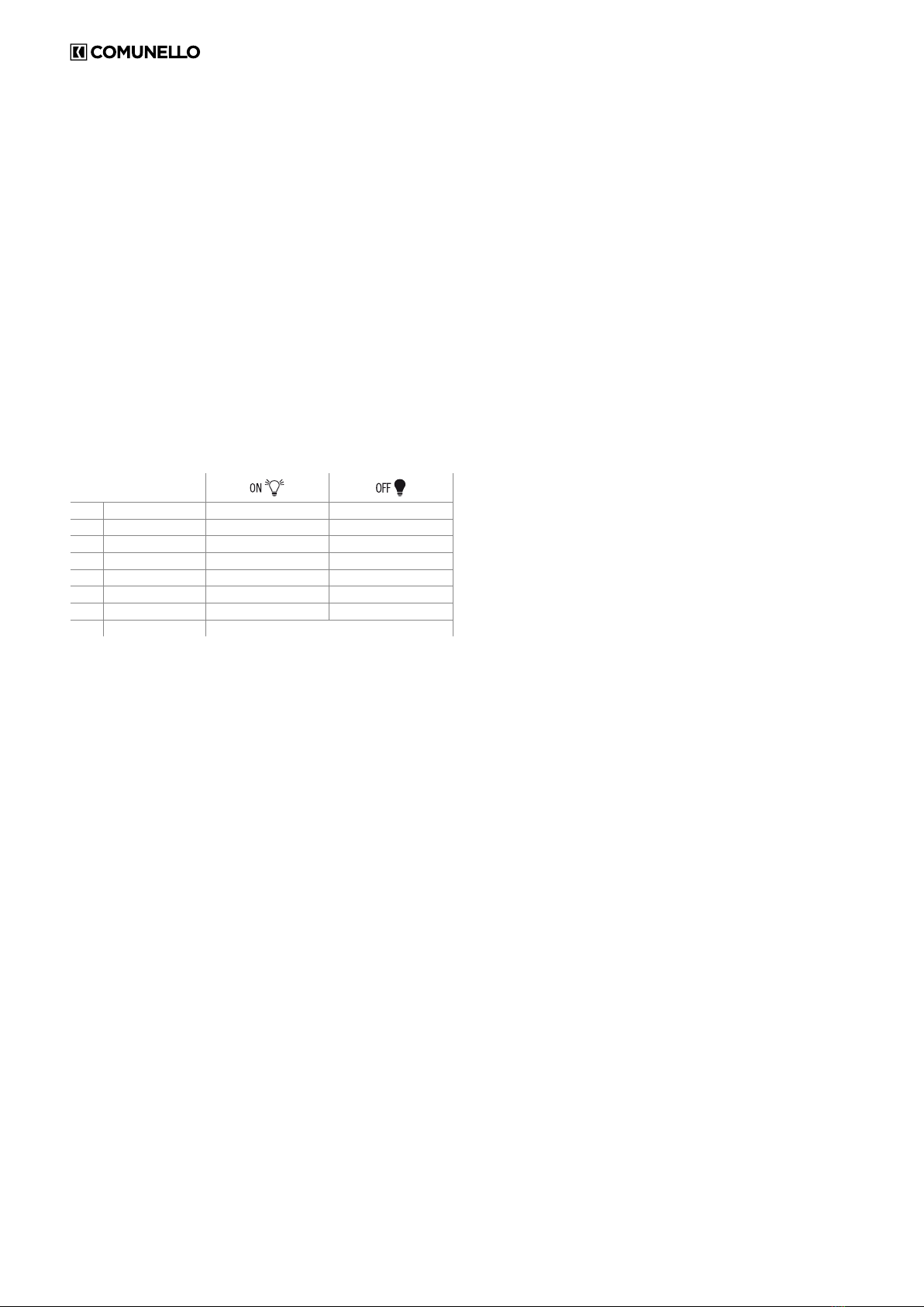
MAIN MENU
The control unit is factory set to allow the selection of several important
functions.
L1 DIR Left Open Right Open
L2 STEP BY STEP Step-by-Step Automatic
L3 CODE TX Code entered No code
L4 CONDO ON OFF
L5 MOTOR TIME Programmed time 30 sec.
L6 PAUSE TIME With automatic closing Without automatic closing
L7 AUTO PROGRAM ON OFF
LEV MENU ON
1. OPENING DIRECTION (DIR):
In the default conguration the control unit is set with “OPEN TO RIGHT”
logic (seen from the operator side, with operator installed to the right of
the sliding leaf); if the “OPEN TO LEFT” logic must be enabled (seen from
operator side, with operator installed to the left of the sliding leaf), proceed
as follows: use the SELECT key to select the blinking OPEN DIRECTION
LED and then press the SET key: the OPEN DIRECTION LED becomes
steady on and programming will be completed. Repeat the procedure if you
wish to restore the previous conguration.
2. STEP-BY-STEP:
In the default conguration the control unit is set with “Step-by-Step”
operating logic enabled (LED n2 on); if the “Automatic” operating logic is
required (LED n2 on), proceed as follows; use the SELECT key to select
blinking LED n2 and then press the SET key: LED n2 will switch off and
programming will be completed.
If the “Step-by-Step 1” operating logic is required, repeat the operation
above described, by pressing the SEL key twice instead only one (to obtain
the quick blinking of LED .
Repeat the procedure if you wish to restore the previous conguration.
3. TX CODE: (REMOTE CONTROL CODE)
Up to 120 remotes with different codes, either of the xed or the rolling
code type can be saved on the control unit.
Programming:
Programming of the transmission code is performed as follows: use the
SELECT key to select blinking LED L3. Press SET once; the LED will change
its blinking mode (longer 1 0 1 0) to show that the rst level is being saved.
On sending the selected code with the required remote, the CODE LED
will remain steady on to indicate that programming has been completed.
To save the code for pedestrian opening / single leaf proceed as follows:
use the SELECT key to select blinking CODE LED L3. Press SET twice
consecutively; the LED will change its blinking mode (1 1 0 1 1 0) to show
that the pedestrian code is being saved. On sending the selected code
with the required remote, CODE LED L3 will remain steady on to indicate
that programming has been completed.
NOTE: After each programming of a valid code, the control panel
waits for a subsequent code for another 10 sec.
If all 120 codes have been saved, repeating the programming operation will
cause all the programming LEDs to start blinking to signal that no further
codes can be saved.
Deletion.
Use SELECT to go to LED L3; activate blinking of the code to be deleted
(CODE or PEDESTRIAN identied by the respective blinking); press and
hold down SET for > 5 s. After this interval the LED will switch off for 2
seconds and the procedure is completed. If all CODE and PEDESTRIAN
codes are deleted, the LED will remain off.
If only PEDESTRIAN codes remain stored, the LED blinking mode will
change (1 1 1 1 0 1 1 1 1 0)
Rule of the rst saved Remote control:
When programming remotes the following rule is applied: if the rst remote
to be saved is of the rolling code type, the receiver will subsequently
accept only rolling code remotes, thus providing enhanced anti-intrusion
security; if the rst remote to be saved is a xed code type, the receiver will
subsequently accept both xed code remotes and rolling code remotes,
although only the xed part of the latter will be controlled (thus effectively
relinquishing the security of the rolling code system).
IMPORTANT: Whenever a reset is performed the receiver is restored to the
factory settings so the rst remote rule logic will be reset.
4. CONDO:
The Condominium function means that during the opening movement or
during the pause time the control unit will not respond to commands sent
by Pushbuttons or remotes. In contrast, during the closing movement a
command sent by the Pushbuttons or the remotes will reverse the direction
of movement. This operating mode is invaluable when the automation
includes a loop detector. In the default conguration the control unit is set
with the Condominium function disabled; if the Condominium function is
required, proceed as follows: use the SELECT key to select blinking LED L4
and then press the SET key: LED L4 becomes steady on and programming
will be completed. Repeat the procedure if you wish to restore the previous
conguration.
5. MOTOR TIME:
(Programming of the motor run time with max 4 minutes). The control unit
is factory set with a preset motor time of 30 seconds without deceleration.
If motor time must be changed, programming must be carried out with the
gate closed as follows: use the SELECT key to select blinking LED L5 and
then press the SET key momentarily; the operator will start the opening
movement; when the required deceleration starting point is reached
press the SET key again; at the same time the operator will decelerate
and reach the required position; press SET to terminate the opening cycle.
Thereafter LED L5 will start blinking rapidly; now repeat the motor time and
deceleration programming procedure for the closing cycle. If you do not
require the control unit to perform the deceleration, during programming,
when the open-close cycle has been completed press the SET key twice
consecutively rather than just once. During programming, instead of the
SET key on the control unit you can use the button on the remote, providing
the remote has been saved beforehand.
6. PAUSE TIME:
(Automatic closing time programming 4 min. max.) The control unit is
factory set with automatic closing disabled. If you wish to enable automatic
closing proceed as follows: use the SELECT key to select blinking LED L6
and press the SET key momentarily; now wait for a time equivalent to the
required time; press the SET key again momentarily and at the same time
the automatic closing time will be saved and LED L6 will remain steady on. If
you wish to restore the initial condition (no automatic closing) select blinking
LED L6 and then press the SET key twice consecutively in a time period
of 2 seconds. The LED will switch off and the operation will be completed.
During programming, instead of the SET key on the control unit you can use
the button on the remote, providing the remote has been saved beforehand
7. AUTO PROGRAM:
The control unit offers the facility of Automatic Programming (SIMPLIFIED).
First bring the gate leaves to an intermediate position, use the SELECT
key to select blinking LED L7 and then hold down the SET key; the control
unit executes the Auto programming procedure by performing a complete
open-close cycle (keep the SET key pressed until Auto Programming is
completed). During the Auto Programming procedure the Deceleration
cycle is set automatically at approximately 15% of the complete cycle.
During Automatic Programming, instead of the SET key on the control unit
you can use the button on the remote, providing the remote has been
saved beforehand.

17
COMUNELLO ®Copyright 2016 - All right reserved
ENGLISH
EXTENDED MENU 1
The control unit is factory set to allow direct selection exclusively of the main
menu functions. If you wish to enable the functions described in Extended
Menu 1, proceed as follows: select blinking LEV LED and press SET once.
The LED will start blinking. This means there will be 30 seconds to select
the functions of Extended Menu 1 using the SELECT and SET keys; once
an additional 30 seconds have elapsed the control unit reverts to the main
menu.
L1 FOTOTEST ON OFF
L2 PEDESTRIAN TIME ON OFF
L3 DECELERATION OFF ON
L4 ELEC BRAKE ON OFF
L5 RELEASE STROKE ON OFF
L6 SLAM LOCK ON OFF
L7 COURTESY LIGHT ON OFF
LEV MENU 1 FLASH
1. FOTOTEST: (Photocells test)
The control unit is factory set with the photocells test disabled. To enable the
test, proceed as follows: make sure you have enabled Extended Menu 1,
use the SELECT key to select blinking LED L1 then press the SET key, LED
L1 becomes steady on and the programming procedure will be completed.
Repeat the procedure if you wish to restore the prior conguration.
2. PED. MOT. T: (Programming of pedestrian motor time, 4 minutes
max).
The control unit is factory set with a preset Motor time (Pedestrian) of
10 seconds without deceleration. If the pedestrian motor time must
be changed, programming must be carried out with the gate closed as
follows: make sure you have enabled Extended Menu 1, use the SELECT
key to select blinking LED L2, then press the SET key momentarily; the
Operator will start an Opening cycle; when the gate reaches the required
initial deceleration point press the SET key again: LED L2 will start blinking
more slowly and the Operator performs the deceleration; when the required
position is reached press the SET key to terminate the Opening cycle. At
this point LED L2 returns to the normal blinking speed and the Operator
restarts in the Closing movement; repeat the operations described above
for the Closing movement. If you do not require the control unit to perform
the deceleration, during programming, when the open-close cycle has
been completed press the SET key twice consecutively rather than just
once. During programming, instead of the SET key on the control unit you
can use the button on the remote, providing the remote has been saved
beforehand.
3. DECELERATION:
As mentioned earlier, the control unit allows programming of a deceleration
stage during opening and closing. However, if no deceleration is required,
this stage can be inhibited. If, before excluding the deceleration stage it had
already been programmed using the Motor Times Programming function,
programming must be repeated from the beginning. If the deceleration
stage is to be excluded proceed as follows: make sure you have enabled
Extended Menu 1, use the SELECT key to select blinking LED L3 and
then press the SET key: LED L3 becomes steady on and programming will
be completed. Repeat the procedure if you wish to restore the previous
conguration.
4. ELECTRONIC BRAKE:
The control unit is factory set with the electronic brake function enabled.
To disable the function, proceed as follows: make sure you have enabled
Extended Menu 1, use the SELECT key to select blinking LED L4 then
press the SET key, LED L4 will switch off and the programming procedure
will be completed.
With the brake enabled, the control unit reduces the progress of the gate
due to inertia, in correspondence with a stop or an inversion command.
Repeat the procedure if you wish to restore the previous conguration.
5. RELEASE STROKE:
The control unit is factory set with the release stroke function disabled. To
enable the Release Stroke function at maximum power, proceed as follows:
make sure you have enabled Extended Menu 1, use the SELECT key to
select blinking LED L5 then press the SET key, LED L5 becomes steady on
and the programming procedure will be completed. If you wish to enable
the Release Stroke function at the power set with the “FORCE” trimmer,
repeat the procedure described above,
press the SELECT key twice (LED L5 will blink rapidly) rather than just once.
Repeat the procedure if you wish to restore the initial conguration.
This procedure makes it possible to facilitate release of the gate lock and
thus allow correct execution of the opening stroke. With this function, before
starting the opening stroke the control unit sends a closing command for 2
seconds with the thrust force associated with the selection made.
6. SLAM LOCK:
The control unit is factory set with the Slam Lock function disabled. This
function consists in adding, in the presence of a deceleration stage during
closing, 1 extra second at the maximum power or at the power selected
with the “FORCE” trimmer, in such a way as to ensure positive engagement
of the gate lock, if installed. If you wish to enable the Slam Lock function
at maximum power, proceed as follows: make sure you have enabled
Extended Menu 1, use the SELECT key to select blinking LED L6 and then
press the SET key: LED L6 becomes steady on and programming will be
completed. If you wish to enable the Slam Lock function at the power set
with the “FORCE” Trimmer, repeat the operation described by pressing the
SELECT key twice (LED L6 will blink rapidly) rather than once. Repeat the
procedure if you wish to restore the initial conguration..
7. PREFLASHING/COURTESY LIGHT:
The control unit is factory set with the Preashing and Courtesy Light
functions disabled. If you wish to enable the Preashing function proceed
as follows: make sure you have enabled Extended Menu 1, press the
SELECT key to select blinking LED L7 and then press the SET key: the LED
becomes steady on and programming will be completed. If you wish to
enable the Courtesy Light function, repeat the operation described above,
pressing the SET key twice (the LED will blink rapidly) rather than once.
Repeat the procedure if you wish to restore the initial conguration.
Preashing Operation: The 24 ~4W max. ashing light output will
always switch on 3 seconds before the gate starts the closing operation.
Courtesy Light Operation: The 24 ~4W max. courtesy light output will
switch on for 3 minutes whenever an opening command is transmitted.
EXTENDED MENU 2
The control unit is factory set to allow selection exclusively of the main menu
functions. If you wish to enable the functions described in Extended Menu
2, proceed as follows: select blinking LED LEV and press SET twice. The
LED will start blinking alternately 1 1 0 1 1 0 1 1 0. This means there is a
period of 30 seconds to select the functions in Extended Menu 2 using the
SELECT and SET keys and then, after a further 30 seconds, the control unit
will revert to the main menu.
L1 SOFT STOP ON OFF
L2 SOFT START ON OFF
L3 SAFE 1 IN OPEN ON OFF
L4 HOLD-TO-RUN ON OFF
L5 FOLLOW ME ON OFF
L6 PAUSE FLASHING ON OFF
L7 ALWAYS CLOSE ON OFF
LEV LEV LONG FLASHING
1. SOFT STOP:
The control unit is factory set with the Soft Stop function disabled. If you
wish to enable the function, proceed as follows: ensure you have enabled
Extended Menu 2 and then use the SEL key to select blinking LED L1
and press the SET key; at the same time LED L1 becomes steady on and
programming will be completed. With this function enabled at the end of the
movement the control unit will reduce operator force to zero gradually in a
2 second interval. Repeat the procedure if you wish to restore the previous
conguration.
2. SOFT START:
The control unit is factory set with the Soft Start function enabled. If you
wish to enable the function, proceed as follows: ensure you have enabled
Extended Menu 2 and then use the SELECT key to select blinking LED
L2 and press the SET key; at the same time LED L2 becomes steady
on and programming will be completed. With this function enabled at
the start of each movement the control unit will regulate start-up of the
operator, gradually increasing the force from the minimum to the value set
by the “FORCE” trimmer during the rst 2 seconds of operation. Repeat the
procedure if you wish to restore the previous conguration.

18 COMUNELLO ®Copyright 2016 - All right reserved
Note: when the Soft Start function is enabled the control unit automatically
disables the Starting Torque function, while if Soft Start is disabled then
Starting Torque is automatically enabled.
3. SAFE 1 also in opening:
The control unit allows the operation of input DS1 to be modied. If you
want SAFE 1 to operate also during opening (momentary stopping of the
gate, as soon as the safety is freed the control unit resumes the opening
movement), proceed as follows: ensure you have enabled Extended Menu
2 and then press the SEL key to select blinking LED L3 and press the SET
key: LED L3 becomes steady on and programming will be completed.
Repeat the procedure if you wish to restore the initial conguration.
4. HOLD-TO-RUN:
The control unit provides the opportunity to set the “Hold-to-run” function.
If you wish to enable the function, proceed as follows: ensure you have
enabled Extended Menu 2 and then use the SELECT key to select blinking
LED L4 and press the SET key; at the same time LED L4 becomes steady
on and the operation will be completed.
With this function enabled using either the remotes or the Pushbuttons to
operate the gate, the following operation will be obtained: the command
must be maintained constantly to move the gate. When the command is
released movement will stop immediately. Repeat the procedure if you wish
to restore the previous conguration.
5. FOLLOW ME
The control unit allows the “Follow me” function to be congured;
programmable only if a Pause Time has already been set, this function
reduces the Pause Time to 5 seconds after freeing the SAFE1 photocell,
meaning the gate re-closes 5 seconds after transit of the user. To activate
this function proceed as follows: ensure you have enabled Extended
Menu 2 and then press the SELECT key to select blinking LED L5 and
then press the SET key: LED L5 becomes steady on and programming will
be completed. Repeat the procedure if you wish to restore the previous
conguration.
6. FLASHING LIGHT OPERATION
The control unit is factory set with Flashing Light during Pause Time
disabled. If you wish to enable this function, proceed as follows: make
sure you have enabled Extended Menu 2, press the SELECT key to select
blinking LED L6 and then press the SET key: LED L6 becomes steady on
and programming will be completed. Repeat the procedure if you wish to
restore the previous conguration.
7. ALWAYS CLOSE FUNCTION
The control unit provides the facility to set “Always Close” operation: this
function, which is programmable only if a Pause Time has already been
programmed, is activated after a power loss; if the gate open condition
is conrmed a closing movement is started automatically, preceded by
5 seconds of preashing. If you wish to enable the function, proceed as
follows: ensure you have enabled Extended Menu 2 and then use the SEL
key to select blinking LED L7 and press the SET key; at the same time LED
L7 becomes steady on and the operation will be completed. Repeat the
procedure if you wish to restore the previous conguration.
RESET:
If it becomes necessary to reset the control unit to restore the factory
settings, press the SELECT and SET keys together; this will cause all the
RED indicator LEDs to light simultaneously followed immediately by the
control unit switching off.
DIAGNOSTICS:
Photocell Test:
The control unit is prearranged for connection of safety devices in
compliance with standard EN 12453 point 5.1.1.6. At each operating
cycle a functional test of the connected photocell is performed. In the case
of an open circuit and/or malfunctioning of the photocell, the control unit
does not enable movement of the gate and visually signals the test failed
condition by causing all the indicator LEDs to blink simultaneously. As soon
as correct operation of the photocell is restored, the control unit is ready
for normal use. This operating mode guarantees failure mode monitoring in
compliance with EN 954-1 Category 2.
Commands input test:
In correspondence with each low voltage command input the control unit
is equipped with an indicator LED so that the status of the input can be
checked at a glance.
Operating logic: LED on input closed, LED off input open.
WARRANTY
a) In business relationships or in case of products sold for professional
use, this warranty is limited to the repair or replacement of product parts
that FRATELLI COMUNELLO SPA acknowledges as defective, through
equivalent re-manufactured Products (the Conventional Warranty); the
warranty does not include the costs necessary for repairing or replacing the
material (e.g. labour costs, rental of equipment etc).
b) The provisions contained in articles 1490 to 1495 of the Italian Civil Code
shall not apply.
c) FRATELLI COMUNELLO SPA warrants the proper operation of the
products within the limits indicated in a) above. Unless otherwise agreed,
the validity of the Conventional Warranty is 24 (twenty-four) months from
the production date, which can be found on the products. The Warranty
shall be effective and binding on COMUNELLO only if the product has
been correctly installed and maintained in accordance with the installation
and safety rules set out in the documentation provided by COMUNELLO or
otherwise available on the website http://www.comunello.com/corporate/
general_conditions_sales/
d) The warranty does not cover: failures or damage caused by transport;
failures or damage caused by defects in the electrical system of the buyer
and/or by carelessness, negligence, inadequate or abnormal use of such
system; failure or damage due to tampering carried out by unauthorized
personnel or due to incorrect use / installation (in this regard, system
maintenance at least every six months is recommended) or the use of non-
original spare parts; defects caused by chemical agents and/or atmospheric
phenomena. The warranty does not cover the cost of consumables; in
any event, COMUNELLO shall be entitled to a consideration for the work
performed at the Customer, where such work proves useless as the
warranty did not apply or because the customer had used the Comunello
product in a negligent, reckless or incompetent manner, such that the
proper use of the product could have avoided the work.
e) Implementation terms: unless otherwise agreed, the right to the
Conventional Warranty is exercised by showing a copy of the purchase
document (invoice) to COMUNELLO. Any defect must be notied to
COMUNELLO within the time limit of thirty (30) days from detection of
the defect. The action must be exercised within the limitation period of
6 (six) months from detection of the defect. The Product parts for which
the Customer requests application of the Conventional Warranty must be
returned by the Customer to FRATELLI COMUNELLO SPA, Via Cassola 64,
36027 Rosà (VI) Italy.
f) The Customer cannot claim compensation for indirect damage, loss of
prots, loss of production and in any case it cannot claim compensation for
an amount that exceeds the value of the supplied components or products.
All transport costs for Products that have been repaired or to be repaired,
although covered by the Conventional Warranty, shall be charged to the
Customer.
g) No external work carried out by Comunello technical staff is covered by
the Conventional Warranty.
h) Specic amendments to the Conventional Warranty conditions described
herein can be dened by the parties in their commercial contracts.
i) The Court of Vicenza (Italy) shall be the place of jurisdiction for any dispute
which will be settled according to the Italian laws.

FRATELLI COMUNELLO S.P.A.
AUTOMATION GATE DIVISION
Via Cassola, 64 - C.P. 79
36027 Rosà, Vicenza, Italy
Tel. +39 0424 585111 Fax +39 0424 533417
Other manuals for CU-230V-1M
1
Table of contents
Other Comunello Control Unit manuals

Comunello
Comunello CU-110V-1M User manual

Comunello
Comunello CU-24V-2M User manual

Comunello
Comunello QUAD - 24V - 2M User manual

Comunello
Comunello CU-24V-1M User manual

Comunello
Comunello CU-230V-1M User manual

Comunello
Comunello CU 230V HP User manual

Comunello
Comunello CU 230V HP User manual

Comunello
Comunello CU 24V 2M ONE User manual

Comunello
Comunello CU 230V HP User manual

Comunello
Comunello QUAD 24V HP User manual