info@con-formgroup.com.au
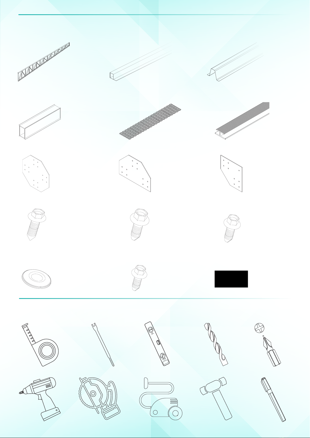
Tools Needed Parts
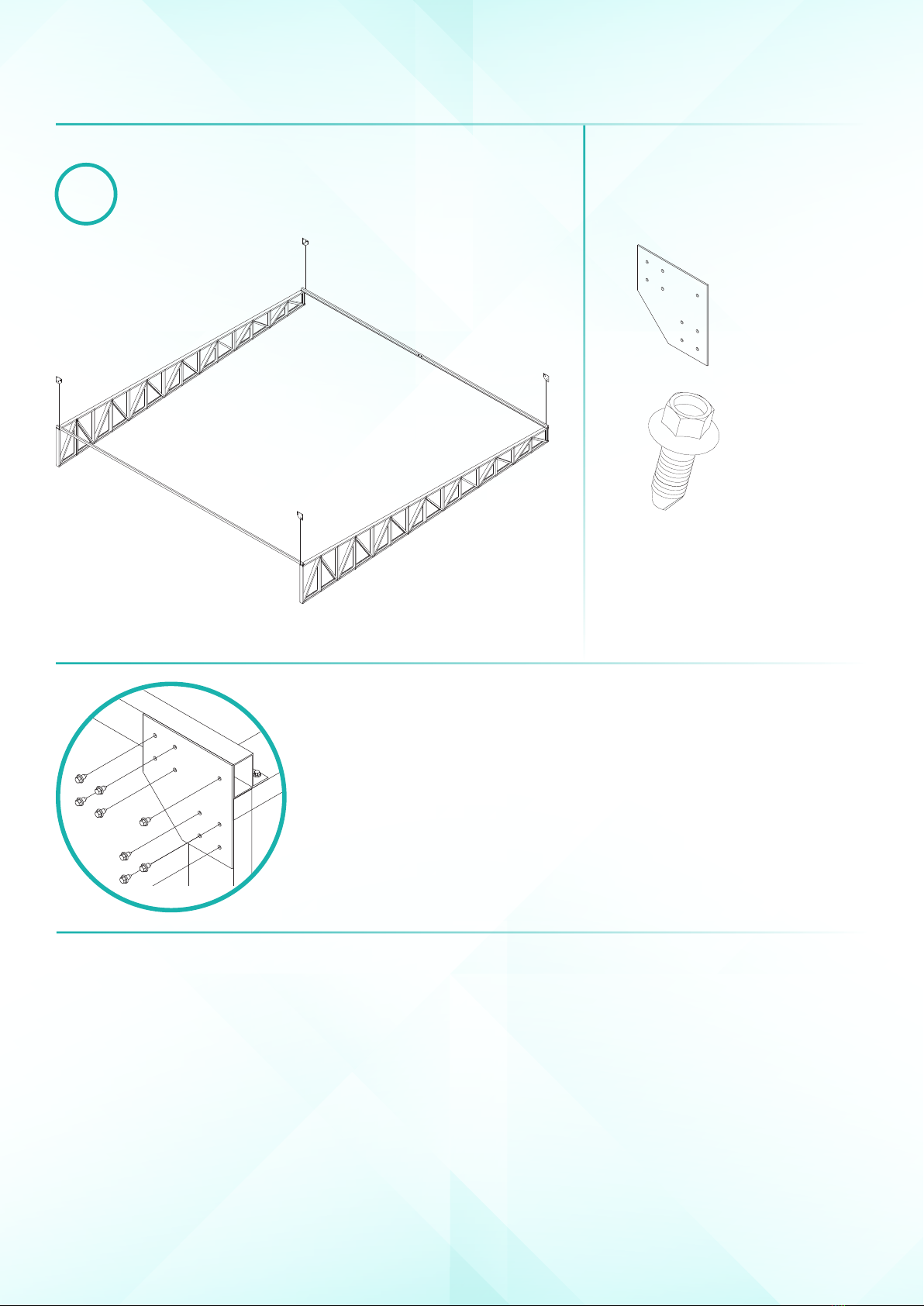
Tape Measure Truss Frames
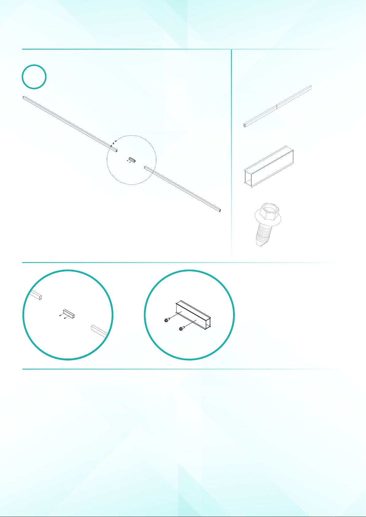
Black Marker RHS Cross Supports
Spirit Level Cross Support Splice
Impact Driver Top Hat Cross Supports
PH2 Phillips Head Bits Top Hat Splice
5/16” Hex Head Driver Bit Full Star Brace
Drill Half Star Brace
High-Speed Drill Bit Kit Quarter Star Brace
Nibbler Drill Attachment C-Channel Horizontal Brace
Circular Saw Diagonal Truss Brace
Mallet Mesh Sheet
18V Wet/Dry Vac Skin Mesh Joiner
Mesh Edge Bar
35mm Self Drilling Tek Screws
35mm Needle Point Screws
20mm Tek Screws
16mm Tek Screws
Hold Down Discs
Certication Plate