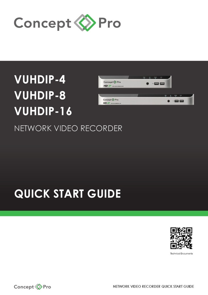
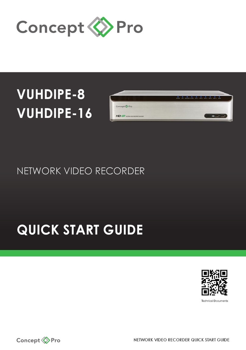
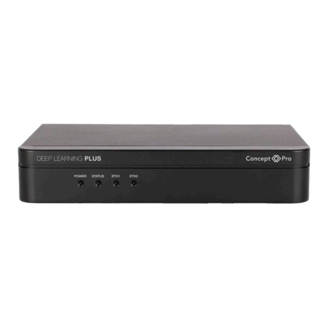
Concept Pro VUHDIPL-4 User manual

VUHDIPL-4
VUHDIPL-8
VUHDIPL-16
NETWORK VIDEO RECORDER
QUICK START GUIDE
NETWORK VIDEO RECORDER QUICK START GUIDE
Technical Documents

NETWORK VIDEO RECORDER QUICK START GUIDE
1. WHAT’S IN THE BOX?
Packaging Contents
Network Video Recorder x1 Quick Start Guide x1 DC48V Power Adapter x1
AC Power Cord x1 5-Pin Terminal Block x2 USB Mouse x1
Remote Control x1 Cable Clamp x1 Cable Clamp Screws x2
Remote Control Batteries x2
2. INSTALLATION
Rear Panel
1
1
2
3
45
6
7
7
7
8
8
8
6
6
5
5
4
4
10
3
3
2
2 9
1
A - VUHDIPL-4
B - VUHDIPL-8
C - VUHDIPL-16
No Name Description
1CAM1 – CAM4 (VUHDIPL-4)
CAM1 – CAM8 (VUHDIPL-8/16)
Ethernet ports used for connecting and providing power to network video cameras
through Power over Ethernet protocol (Max. 15W per channel).
2 ETHERNET/WAN (UPLINK) Network port for connection to the Internet, router, or hub.
3 VGA VGA display output for connection to a main display monitor
(Max. 1920x1080 display resolution).
4 HD MONITOR HDMI display output for connection a main display monitor
(Max. 3840x2160 display resolution).
5 ALARM IN Alarm input terminals (AI1, AI2, GND).
6 RS-485 Communications port for connecting peripheral equipment such as a control keyboard.
7 ALARM OUT Alarm relay output port (N/O, N/C, COM).
8 DC48V Power input for the NVR.
9 LAN (DOWNLINK)
(VUHDIPL-16 only) Network port dedicated for the 8CH PoE Expansion Hub accessory
10 SPOT OUT
(VUHDIPL-16 only)
BNC display output port for connection to a spot monitor
A
B
C
Technical Documents

NETWORK VIDEO RECORDER QUICK START GUIDE
POS
ATM
Access
Controller
WAN
(UPLINK)
LAN
(DOWNLINK)
AUDIO OUT
AUDIO IN
VGA
HD MONITOR
DC 48V
SPOT OUT
ALARMIN
IN9
IN11
GND
IN13
IN15
IN10
IN12
GND
IN14
IN16
ALARMIN
RELAY RS485
NC
COM
NO
IN8
IN6
GND
IN4
IN2
D-
D+
IN7
GND
IN5
GND
IN3
IN1
UPKINK DOWNLINK
Control
Device
Sensor
Alarm
Monitor
IP Camera
Internet
Ne
twork
A
ttached
Storage
CMS,
Web viewer
Mobile viewer
IP Camera
Extender Hub
Alarm
If the IP camera supports alarm input/out, the signal may be supported over the Ethernet cable.
Refer to the IP camera user manual for more details.
Front Panel
No Name Description
1 IR REMOTE CONTROL RECEIVER Receives the control signal from included remote control.
2 USB For connecting USB devices such as a mouse or memory drive.
3 STATUS LED Displays the status of Power, Recording, Network, and Alarm.

NETWORK VIDEO RECORDER QUICK START GUIDE
3. GETTING STARTED
Setup Wizard
The Setup Wizard will help congure important system settings when the device is rst booted up.
Create a new, complex password to properly secure the device.
This step is highly recommended for device security.
This step is highly recommended for device security, however please be sure to remember
the password in order to prevent becoming locked out of the NVR.
Import settings from another device or click Next to begin conguring the device.
Set the system time zone and date/time format. Manually set the date and time if desired.
Log in

NETWORK VIDEO RECORDER QUICK START GUIDE
1. The log-in screen will appear after the system boots up.
2. Select a user ID and enter the corresponding password. The default user ID is “ADMIN” and
the default password is “1234”.
3. Click <OK>.
For security purposes, please change the password to a more complex, secure password
after logging in the rst time.
Status Bar: The status bar can be used in addition to the included remote control to access
key features.
Icon Description Icon Description
[MENU] Select system setup, record setup,
search, and archiving menus.
[ZOOM] Move to the Digital Zoom screen.
[ID] Displays the currently logged in
user ID.
[LOG] Lists recent recording events.
[UI MODE] Click to always pin the status bar
and timeline or disable to only show
these by hovering the mouse.
[PANIC] Toggles panic recording for all
channels.
[SPLIT] Select a split-screen view. [ALARM] Blinks when an event occurs. Click to
display a real-time overview of any
events.
[SEQ] Select an alternative split-screen
view or toggle a display sequence.
[NET] Click to check the device network
connection status and review a list of
currently connected users.
[OSD] Display or hide the OSD menu. [DISK] Click to display updated hard disk
information. If the disks are set to
Overwrite, OW will display.
[PTZ] Move to the PTZ Control screen. [DATE] Displays the current time and date.
Quick Menu Timeline
Item Description Item Description
Channel
No.
Displays the number of the
current channel.
Timeline
Date
Displays the date of the current timeline.
Click to select a different date.
Playback Begin playing back the
recorded video of the selected
channel from the specied time.
Zoom In/Out Expand or collapse the timeline.
Zoom Open the digital zoom window
for the selected channel.
Timeline
Navigation
Move to the previous or next point of
time in the timeline. You may also use the
mouse scroll wheel to navigate.
Snapshot Capture a .jpeg snapshot of
the current live video and
reserve to the hard disk or
export to a USB device.
Timeline Bar Visually represents recorded video data. The
colour shown represents a recording type:
- Green: Continuous Recording
- Blue: Motion Recording
- Red: Alarm Recording
- Yellow: Panic Recording
PTZ
Control
Move to PTZ Control window. Double-click anywhere on the timeline to begin playback
from that point. Drag and drop an area on the timeline
to archive the data or perform an event search for the
specied time period.
Cam
Change
Assign the selected screen to
another channel.

NETWORK VIDEO RECORDER QUICK START GUIDE
4. AUTOMATIC RECORDING PROFILES
1. Press [MENU] on the remote control and use the direction buttons to select <RECORD
SETUP>, then press [ENTER].
Alternatively, select <MENU> - <RECORD SETUP> from the status bar.
2. Set <RECORD SETUP MODE> to <AUTO CONFIGURATION>
and select a desired recording prole:
- CONTINUOUS RECORD:
Always record video.
o LONG DURATION BUT LOW QUALITY:
Record video at a low quality, resulting in a longer recording time.
o HIGH QUALITY BUT SHORT DURATION:
Record video at a high quality, but resulting in a shorter recording time.
- MOTION RECORD:
Only record video when motion is detected.
- ALARM RECORD:
Only record video when an alarm event occurs.
- MOTION/ALARM RECORD:
Only record video when motion or alarm events occur.
- INTENSIVE MOTION RECORD:
Record continuously at low quality and switch to high quality when motion events
occur.
- INTENSIVE ALARM RECORD: Record continuously at low quality and switch to high
quality when alarm events occur.
- INTENSIVE MOTION/ALARM RECORD:
Record continuously at low quality and switch to high quality when motion or alarm
events occur.
3. Click <APPLY>.
Additionally, <MANUAL CONFIGURATION> can be selected for a customised recording
prole and schedule.

NETWORK VIDEO RECORDER QUICK START GUIDE
5. SEARCHING RECORDED VIDEO
1. From the <SEARCH> menu, select <TIME SEARCH>.
2. Specify the date and time from the calendar.
3. Identify the type of recording data by the colour in the bar.
- Light Green: Pre-Recording
- Green: Continuous Recording
- Blue: Motion Recording
- Red: Alarm Recording
- Yellow: Panic Recording
4. Click to move to a desired start time in the time bar or use the buttons on the bottom of
the status bar to search.
5. Select an item and click <PLAYBACK>.
Other search options include Thumbnail Search, Event Search, and Text-in Search.

NETWORK VIDEO RECORDER QUICK START GUIDE
6. Activating Video Analytics
Video Analytics
Some Concept Pro cameras come equipped with video analytics functionality, including line
crossing, area entrance/exit, loitering, stopped, and object removed detection, that can be
used from the Concept Pro suite of recorders.
To use video analytics, you must rst ensure the license is recognised by the recorder. To do
this, rst connect the camera to the Concept Pro recorder over the network or through its
PoE ports. Then, through the recorder user interface, navigate to <MENU> - <SYSTEM SETUP>
- <SYSTEM> - <LICENSE>. Click <ADD AUTOMATICALLY> if the recorder is connected to the
network to automatically add the license for all valid connected cameras.
Alternatively, the individual camera license can be found by logging into the camera web
interface, navigating to <SETUP> - <SYSTEM> - <LICENSE>. The license should be listed in this
menu. The license can then be manually added to the recorder <LICENSE> menu should the
automatic option not properly update.
Once the license is applied, simply navigate to the <CAMERA> - <VA SETUP> menu to setup
video analytics. Select the desired channel and turn ACTIVATION to ON.
Click START WIZARD and follow the instructions to congure a new VA rule, calibrate the
accuracy of the camera, and congure related settings. Alternatively, click ADD in the rule
tab to manually congure settings. Click the SCHEDULE tab to customise the VA schedule.
Note: Performing CALIBRATION is recommended to increase the video analytics accuracy.

NETWORK VIDEO RECORDER QUICK START GUIDE
7. Optimising video for image quality & storage requirements
All Concept Pro cameras & recorders come with features designed to help balance the
need for high quality images and lower storage requirements. Selecting the proper settings
for each camera can help optimise your system and balance image quality with storage
requirements.
Constant Bit Rate
Constant Bit Rate (CBR) applies a specic bit rate for the video stream and the camera will
transmit at approximately this bit rate without regard to time, light level, scene complexity, or
other factors. As a result, the image quality will appear improved, but bandwidth and storage
requirements will be the high.
Variable Bit Rate
Variable Bit Rate (VBR) automatically adjusts the bit rate according the scene being
monitored. With VBR enabled, the image quality will decrease when there is less or no motion
occurring and increase when scene complexity increases. As a result, bandwidth and
storage requirements can be considerably reduced while the image quality will be focused
on scenes of actual importance.
To congure VBR+ from the Concept Pro NVR, navigate to <MENU> - <SYSTEM SETUP> -
<CAMERA> - <CAMERA SETUP> - <STREAM SETUP>. Select the desired channel and bit rate
control scheme, then press <APPLY>.
VBR+
Some Concept Pro cameras, such as the CVP5325 series, support a special feature named
VBR+. Similar to other smart codecs, VBR+ is a more intelligent video processing feature that
can more aggressively apply techniques to dramatically reduce the bit rate by only focusing
optimal image quality according to scene complexity.
To congure VBR/CBR from the Concept Pro NVR, navigate to <MENU> - <SYSTEM SETUP> -
<CAMERA> - <CAMERA SETUP> - <STREAM SETUP>. Select the desired channel and VBR+ from
Bit Rate Control, then press <APPLY>.
Regions of Interest
Some Concept Pro cameras, such as the CVP5325 series, support regions of interest directly
through Concept Pro NVRs, others can be congured through web browser. Regions of
Interest can be manually set from the <CAMERA SETUP> menu with the area denoted ‘of
interest’ or ‘not of interest’. According to the setting, the camera will apply optimal image
quality to the area and low image quality to outside areas to help reduce bit rate further.
Auto ROI is another option that allows the camera to intelligently track moving objects and
apply optimal image quality to moving objects only while the background image quality
would be lower.

NETWORK VIDEO RECORDER QUICK START GUIDE
Smart Storage Compression
Concept Pro NVR products support Smart Storage Compression (SSC), a feature designed
to limit the camera bit rate according to the recording FPS value. With Smart Storage
Compression (SSC) off by default, the system will record video streams at higher bit rates, and
preserve this bit rate no matter the record FPS.
With Smart Storage Compression (SSC) set to ON, the system will reduce the maximum bit rate
to 4Mbps for the main stream and 1Mbps for the sub stream. It will also automatically adjust
the max bit rate according to the record FPS setting. SSC therefore attempts to balance
image quality with recording frame rate for additional savings in bandwidth and storage.
H.265
H.265 is a new video compression codec that allows for more optimal compression of video
streams compared to the H.264 video codec. When combined with VBR, this can result in
a considerable reduction in bit rate compared to H.264 without a major trade off in image
quality.
Note: Performance of bit rate control schemes and video compression codecs depends
upon the installation environment.

NETWORK VIDEO RECORDER QUICK START GUIDE
8. Archiving Recorded Video
1. Click <MENU> and select <ARCHIVING>. This can be selected from either the Live or
Playback screens. From <ARCHIVING>, select <NEW ARCHIVING>.
2. Select a date for the archive from the calendar to the left. Any dates containing
recorded data will be coloured boxes.FIRST: Automatically select the rst date with
recorded video.LAST: Automatically select the last date with recorded video.Check the
<START> and <END> times. Drag the timeline to specify the start and end times.
3. Check the appropriate boxes for desired <CHANNEL>, <LOG>, <CODEC>, and <PLAYER>
to be included in the archive.
4. Click <QUERY>. The results will be listed in the <ARCHIVING INFO> window.
5. i. The maximum backup capacity for one time is 20GB. If the archiving request
exceeds 20GB, the end time will be automatically adjusted so the le is under 20GB.
6. To export to an external USB storage device, connect the device to the NVR and click
<EXPORT>.
7. To reserve the data, click <RESERVE>. Enter a <TAG NAME> and click <OK>.
Click <RESERVE> to save the archive to the internal hard disk.
8. i. Reserved data will not be erased by the NVR, even if it is set to overwrite mode.
This is useful for safely backing up data when an external USB storage device is not
currently available. Note that reserving data necessarily reduces the remaining
recording capacity of the NVR. After exporting the reserved data to an external
device, deleting the reserved item from the internal disk to free up more recording
space is recommended.
9. To exit the <ARCHIVING> menu, click <CLOSE>.

NETWORK VIDEO RECORDER QUICK START GUIDE
9. ACCESSING FROM THE WEB
1. Note the device IP address and HTTP port number from the Network Status menu. From
a PC connected to the network, open Internet Explorer and enter the device address in
the address bar. Internet Explorer is recommended for the best web access experience,
however other web browsers such as Firefox and Chrome are supported with reduced
functionality.
2. When prompted, install the required ActiveX controls.
3. Log-in using the recorder user credentials.
4. View Live Video, Search and Playback recorded video, Archive video, and congure
recorder options from the respective tabs.

NETWORK VIDEO RECORDER QUICK START GUIDE
10. ACCESSING FROM THE CONCEPT PRO VIEWER MOBILE APP
From an iOS App Store or Android Play Store, search for the free
“Concept Pro Viewer” app. Install and open the application. Add
the device via QR Code, DDNS Details, or IP Address.
SEQURINET REGISTER / LOGIN
You will need to register your details with Sequrinet to set up any recording devices.
You can login or set up your Securinet account with the Concept Pro App.
APP SETUP
Connect to router or switch with router attached via a network patch cable.
Navigate to the network menu in the recorder and either select DHCP or alternatively statically assign
a valid IP address for your local network. Apply all settings and select Close
Concept Pro Viewer
Complete the elds
and click Sign up.
Click OK.
Tap Touch here
to login Sequirnet
Already registered?
Complete your details and
press log in. Proceed to step 3.
Click Sign up to register for a
Sequirinet account.
Open the app and
select the “+” icon
(this opens up the
setup page for the
connection).
Press the QR code
icon on the screen and
this opens the phone’s
scanner.

NETWORK VIDEO RECORDER QUICK START GUIDE
NVR SETUP
Select Menu at the bottom left hand corner of the screen and select Sequrinet at the top of the list.
A QR code will appear.
Going back to your App on your smart phone, tap on the QR code icon and point the phone at the QR
code on the DVR. The phone will scan the code and the Mac code will populate the address section
on the phone.
Tap on the DVR/NVR Nickname section and add a unique name for the
connection (You can enter anything here)
Tap on the DVR/NVR ID section and enter the username in here (Please enter
ADMIN)
Tap on the DVR/NVR Password section and enter the default password or any
password you have programmed on the DVR
Tap Done then Save.
Your connection will now be saved and ready for selection

NETWORK VIDEO RECORDER QUICK START GUIDE

Design and specication are subject to change without notice.
S1477AU01_Rev01
This manual suits for next models
2
Table of contents
Other Concept Pro Network Hardware manuals