3
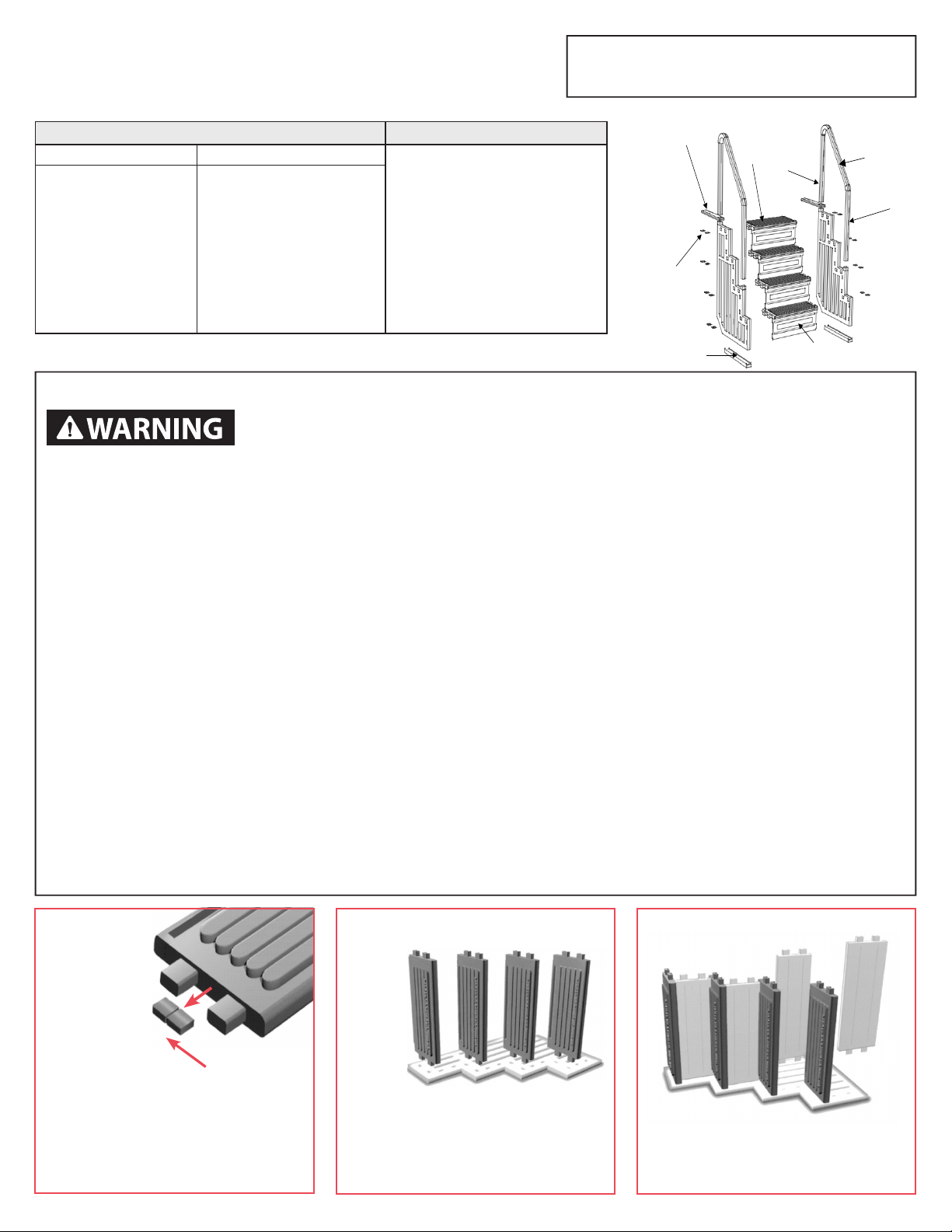
Secure each step by fully inserting the
locking wedges, saved from step #1, between
the side panel and the top surface of both
ends ofeach step.
Position the
base under the
side panel. Secure the
base to each side panel
with four #10 x 1-1/4” screws.
Use the molded locators on each
tab of the base.
Position the second side panel over the steps
and risers and press the panel down so that
each step and riser are fully seated into the
second side panel. It may be necessary to tap
the side panel, using a mallet or a hammer
and block of wood, to fully seat it.
If you are assembling this unit for use with an enclosure kit
or SIG system do not attach the mounting brackets. Afx
the “No diving” labels as indicated in step 9 below and continue to step 10.
STOP!
SAND
Note:
40 lbs.
of sand
required!
Pour
sand into
funnel.
Pour
sand into
funnel.
Spray the inside opening of the mounting
brackets with liquid soap or spray lubricant
and slide a mounting bracket over each of
the two higher handrail posts so that they
extend out away from the steps. Afx the
two “No jumping – No diving” stickers to
the upper end of one of the handrail posts,
one facing the pool and one facing away
from the pool.
Spray the ends of the handrails
with liquid soap or spray lubricant
and slip the ends of the handrails
into the open ends of the posts
until they are fully seated. Secure
in place using one #10 x 1-1/4”
screw per post.
Step 7
Place the assembled unit on the deck near the
pool. Note that there are two sets of handrail
posts-one set 36-1/4” long and one set 43-1/2”
long. Also note that the inside ends of each
handrail post are formed differently - the “top”
end is H-shaped inside to accept the ends of the
handrails and the opposite end is the “plain end”
(the end to be inserted into the side panels).
Spray the “plain ends” of all four handrail posts
with liquid soap or spray lubricant.
Top End – accepts the
ends of handrails..
Plain End – coat
outside of end
with liquid soap or
spray lubricant.
Step 8
Step 9
Step 11
Step 8a.
IMPORTANT: To prevent oating you MUST
do the following: Pour about 10 pounds of dry
sand into each of the four openings indicated
above. Shake unit to distribute the sand evenly.
Adding water may also help to distribute the
sand.
Fasten the long Handrail posts to the side
panels with one #10 x 1-1/4” screw per post
approximately one inch (1”) below the mouth
of the hole in which the post is inserted into
the side panel.
Insert the short posts into
the lower holes of the side
panel to the line indicated
on the post.
Insert the long Handrail
posts into the upper
holes making certain that
ends marked “top” are
pointing up.
Slide mounting
brackets onto
posts.
Carefully place the
assembled unit into the
pool and tip it 45° to the
left, right and forward to fill
steps with water. Repeat if
steps continue to float
Step 10
WARNING! Pool step will
be heavy. Have additional
help. Do not attempt to
place the step by yourself.
Fasten with
Screw to
secure.
Step 4 Step 5 Step 6
Fasten with screw
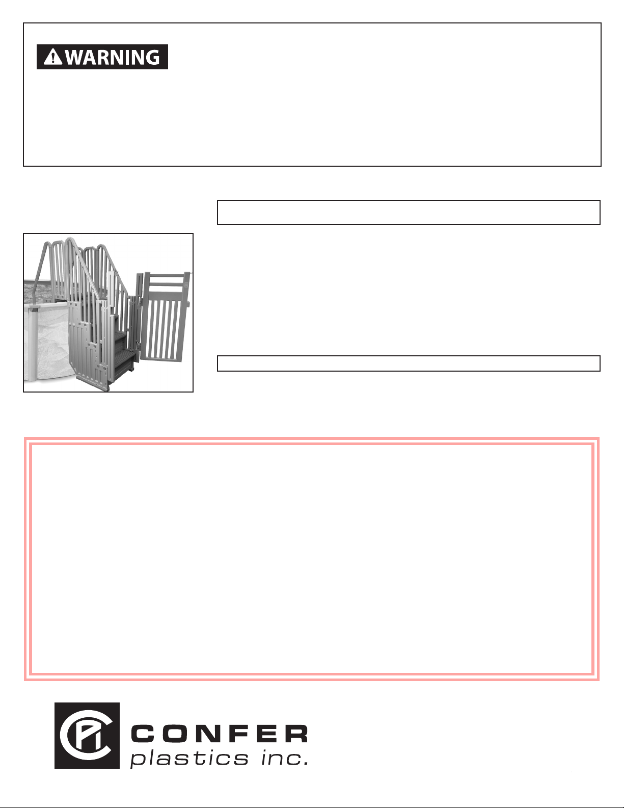
If you are assembling this unit for use with an enclosure
kit or SIG system refer to the instructions supplied with
the kit. Do not attach the handrails to the posts as described below.
STOP! Step 12
Position the unit, between upright posts of the
pool, so that the handrail posts are as close
as possible to the pool top seat. Slide the
mounting brackets down until they reach the
deck surface. Fasten to the deck surface by
drilling two 1/8” pilot holes with a cordless drill,
using the preformed holes in the mounting
brackets as guides. If the bracket is not long
enough to reach the deck surface it will be
necessary to extend that part of the deck
surface so that the brackets can be fastened
down. Secure with two #10 x 1-1/4” screws per
bracket. After fastening the unit to the deck
secure the brackets to the handrail posts using
one #10 x 1-1/4” screw per bracket.
Note: After assembly you
will have two extra #10 x
1-1/4” screws.
WARNING! Using
a corded drill near
pool may result in
electrocution.