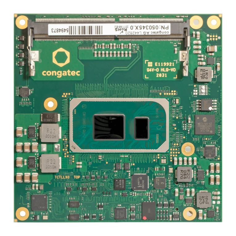
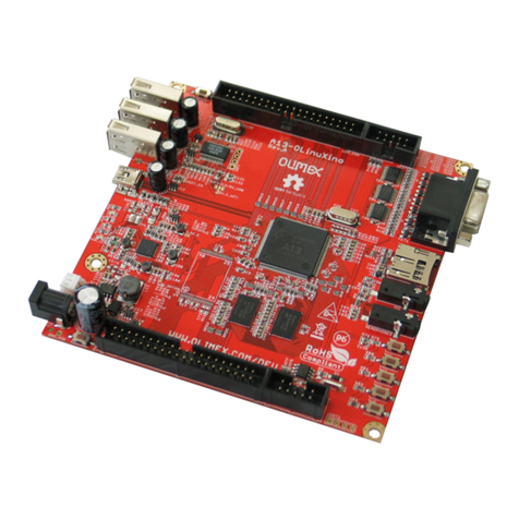
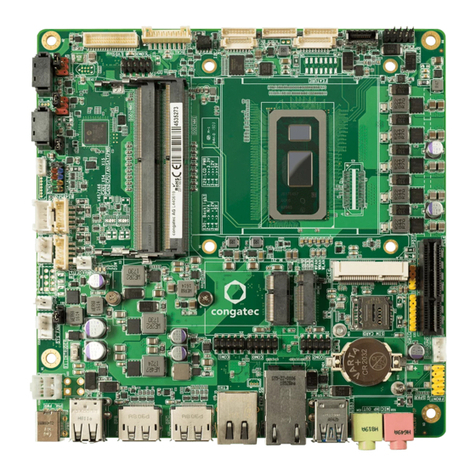
Congatec COM Express conga-TS570 User manual

COM Express™ conga-TS570
11th Generation Intel® Core™ i7, i5, i3, Celeron and Xeon processor with either QM580E, HM570E, or RM590E
Chipset
User’s Guide
Revision 0.1 (Preliminary)

Copyright © 2022 congatec GmbH TSTLm01 2/72
Revision History
Revision Date (yyyy-mm-dd) Author Changes
0.1 2022-02-14 AEM •Preliminary release

Copyright © 2022 congatec GmbH TSTLm01 3/72
Preface
This user’s guide provides information about the components, features, connectors and BIOS Setup menus available on the conga-TS570. It is
one of three documents that should be referred to when designing a COM Express™ application. The other reference documents that should
be used include the following:
COM Express™Design Guide
COM Express™Specification
The links to these documents can be found on the congatec GmbH website at www.congatec.com
Software Licenses
Notice Regarding Open Source Software
The congatec products contain Open Source software that has been released by programmers under specific licensing requirements such as
the “General Public License“ (GPL) Version 2 or 3, the “Lesser General Public License“ (LGPL), the “ApacheLicense“ or similar licenses.
You can find the specific details at https://www.congatec.com/en/licenses/. Search for the revision of the BIOS/UEFI or Board Controller
Software (as shown in the POST screen or BIOS setup) to get the complete product related license information. To the extent that any
accompanying material such as instruction manuals, handbooks etc. contain copyright notices, conditions of use or licensing requirements that
contradict any applicable Open Source license, these conditions are inapplicable.
The use and distribution of any Open Source software contained in the product is exclusively governed by the respective Open Source
license. The Open Source software is provided by its programmers without ANY WARRANTY, whether implied or expressed, of any fitness for
a particular purpose, and the programmers DECLINE ALL LIABILITY for damages, direct or indirect, that result from the use of this software.
OEM/ CGUTL BIOS
BIOS/UEFI modified by customer via the congatec System Utility (CGUTL) is subject to the same license as the BIOS/UEFI it is based on. You
can find the specific details at https://www.congatec.com/en/licenses/.

Copyright © 2022 congatec GmbH TSTLm01 4/72
Disclaimer
The information contained within this user’s guide, including but not limited to any product specification, is subject to change without notice.
congatec GmbH provides no warranty with regard to this user’s guide or any other information contained herein and hereby expressly disclaims
any implied warranties of merchantability or fitness for any particular purpose with regard to any of the foregoing. congatec GmbH assumes
no liability for any damages incurred directly or indirectly from any technical or typographical errors or omissions contained herein or for
discrepancies between the product and the user’s guide. In no event shall congatec GmbH be liable for any incidental, consequential,
special, or exemplary damages, whether based on tort, contract or otherwise, arising out of or in connection with this user’s guide or any other
information contained herein or the use thereof.
Intended Audience
This user’s guide is intended for technically qualified personnel. It is not intended for general audiences.
Lead-Free Designs (RoHS)
All congatec GmbH designs are created from lead-free components and are completely RoHS compliant.
Electrostatic Sensitive Device
All congatec GmbH products are electrostatic sensitive devices. They are enclosed in static shielding bags, and shipped enclosed in secondary
packaging (protective packaging). The secondary packaging does not provide electrostatic protection.
Do not remove the device from the static shielding bag or handle it, except at an electrostatic-free workstation. Also, do not ship or store
electronic devices near strong electrostatic, electromagnetic, magnetic, or radioactive fields unless the device is contained within its original
packaging. Be aware that failure to comply with these guidelines will void the congatec GmbH Limited Warranty.

Copyright © 2022 congatec GmbH TSTLm01 5/72
Symbols
The following symbols are used in this user’s guide:
Warning
Warnings indicate conditions that, if not observed, can cause personal injury.
Caution
Cautions warn the user about how to prevent damage to hardware or loss of data.
Note
Notes call attention to important information that should be observed.
Copyright Notice
Copyright © 2022, congatec GmbH. All rights reserved. All text, pictures and graphics are protected by copyrights. No copying is permitted
without written permission from congatec GmbH.
congatec GmbH has made every attempt to ensure that the information in this document is accurate yet the information contained within is
supplied “as-is”.
Trademarks
Product names, logos, brands, and other trademarks featured or referred to within this user’s guide, or the congatec website, are the property
of their respective trademark holders. These trademark holders are not affiliated with congatec GmbH, our products, or our website.

Copyright © 2022 congatec GmbH TSTLm01 6/72
Warranty
congatec GmbH makes no representation, warranty or guaranty, express or implied regarding the products except its standard form of limited
warranty (“Limited Warranty”) per the terms and conditions of the congatec entity, which the product is delivered from. These terms and
conditions can be downloaded from www.congatec.com. congatec GmbH may in its sole discretion modify its Limited Warranty at any time
and from time to time.
The products may include software. Use of the software is subject to the terms and conditions set out in the respective owner’s license
agreements, which are available at www.congatec.com and/or upon request.
Beginning on the date of shipment to its direct customer and continuing for the published warranty period, congatec GmbH represents that
the products are new and warrants that each product failing to function properly under normal use, due to a defect in materials or workmanship
or due to non conformance to the agreed upon specifications, will be repaired or exchanged, at congatec’s option and expense.
Customer will obtain a Return Material Authorization (“RMA”) number from congatec GmbH prior to returning the non conforming product
freight prepaid. congatec GmbH will pay for transporting the repaired or exchanged product to the customer.
Repaired, replaced or exchanged product will be warranted for the repair warranty period in effect as of the date the repaired, exchanged
or replaced product is shipped by congatec, or the remainder of the original warranty, whichever is longer. This Limited Warranty extends to
congatec’s direct customer only and is not assignable or transferable.
Except as set forth in writing in the Limited Warranty, congatec makes no performance representations, warranties, or guarantees, either
express or implied, oral or written, with respect to the products, including without limitation any implied warranty (a) of merchantability, (b) of
fitness for a particular purpose, or (c) arising from course of performance, course of dealing, or usage of trade.
congatec GmbH shall in no event be liable to the end user for collateral or consequential damages of any kind. congatec shall not otherwise
be liable for loss, damage or expense directly or indirectly arising from the use of the product or from any other cause. The sole and exclusive
remedy against congatec, whether a claim sound in contract, warranty, tort or any other legal theory, shall be repair or replacement of the
product only.
Certification
congatec GmbH is certified to DIN EN ISO 9001 standard.
C
E
R
T
I
F
I
C
A
T
I
O
N
I
S
O
9
0
0
1
TM

Copyright © 2022 congatec GmbH TSTLm01 7/72
Technical Support
congatec GmbH technicians and engineers are committed to providing the best possible technical support for our customers so that our
products can be easily used and implemented. We request that you first visit our website at www.congatec.com for the latest documentation,
utilities and drivers, which have been made available to assist you. If you still require assistance after visiting our website then contact our
Terminology
Term Description
DDI Digital Display Interface
eDP Embedded DisplayPort
EU Execution Units
GB Gigabyte
GHz Gigahertz
HDA High Definition Audio
kB Kilobyte
kHz Kilohertz
MB Megabyte
Mbit Megabit
MHz Megahertz
N.A Not available
N.C Not connected
PCH Platform Controller Hub
PCIe PCI Express
PEG PCI Express Graphics
SATA Serial ATA
S5e Enhanced Soft-Off State
TBD To be determined
TDP Thermal Design Power
TCC Time Coordinated Computing
TSN Time Sensitive Networking

Copyright © 2022 congatec GmbH TSTLm01 8/72
Contents
1 Introduction ............................................................................. 11
1.1 COM Express™ Concept......................................................... 11
1.2 Options Information................................................................. 12
2 Specifications........................................................................... 14
2.1 Feature List .............................................................................. 14
2.2 Supported Operating Systems ................................................ 15
2.3 Mechanical Dimensions ........................................................... 16
2.4 Supply Voltage Standard Power .............................................. 16
2.4.1 Electrical Characteristics .......................................................... 17
2.4.2 Rise Time ................................................................................. 17
2.5 Power Consumption ................................................................ 17
2.6 Supply Voltage Battery Power ................................................. 19
2.7 Environmental Specifications................................................... 19
3 Block Diagram.......................................................................... 20
4 Cooling Solutions..................................................................... 21
4.1 CSA Dimensions ...................................................................... 22
4.2 CSP Dimensions....................................................................... 23
4.3 HSP Dimensions....................................................................... 24
4.4 Heatspreader Thermal Imagery ............................................... 25
5 Connector Rows....................................................................... 26
5.1 Primary and Secondary Connector Rows................................. 26
5.1.1 PCI Express™........................................................................... 26
5.1.2 PCI Express Graphics (PEG) ..................................................... 26
5.1.2.1 PEG Link Configuraton ............................................................ 27
5.1.3 Display Interface ...................................................................... 28
5.1.3.1 DP++ ....................................................................................... 28
5.1.3.2 LVDS/eDP................................................................................. 29
5.1.3.3 VGA.......................................................................................... 29
5.1.4 SATA™..................................................................................... 30
5.1.5 Optional NVMe SSD ................................................................ 30
5.1.6 USB .......................................................................................... 30
5.1.7 Gigabit Ethernet ..................................................................... 31
5.1.8 High Definition Audio (HDA) ................................................... 31
5.1.9 LPC Bus.................................................................................... 31
5.1.10 I²C Bus ..................................................................................... 32
5.1.11 GPIOs....................................................................................... 32
5.1.12 General Purpose Serial Interface ............................................. 32
5.1.13 Power Control .......................................................................... 32
5.1.14 Power Management................................................................. 35
6 Additional Features.................................................................. 36
6.1 congatec Board Controller (cBC) ............................................. 36
6.1.1 Board Information.................................................................... 36
6.1.2 General Purpose Input/Output................................................ 36
6.1.3 Watchdog ................................................................................ 36
6.1.4 I2C Bus...................................................................................... 36
6.1.5 Power Loss Control.................................................................. 37
6.1.6 Fan Control .............................................................................. 37
6.1.7 Enhanced Soft-Off State .......................................................... 37
6.2 OEM BIOS Customization........................................................ 37
6.2.1 OEM Default Settings .............................................................. 38
6.2.2 OEM Boot Logo....................................................................... 38
6.2.3 OEM POST Logo ..................................................................... 38
6.2.4 OEM DXE Driver...................................................................... 38
6.3 congatec Battery Management Interface ................................ 38
6.4 API Support (CGOS) ................................................................ 39
6.5 Security Features...................................................................... 39
6.6 Suspend to Ram....................................................................... 39
7 conga Tech Notes .................................................................... 40
7.1 Adaptive Thermal Monitor and Catastrophic Thermal Protection
40
7.2 Processor Performance Control ............................................... 41
7.2.1 Intel®SpeedStep®Technology (EIST) ...................................... 41
7.2.2 Intel®Turbo Boost Technology ................................................ 41
7.3 Intel®Virtualization Technology ............................................... 42
7.4 Thermal Management ............................................................. 43
7.5 ACPI Suspend Modes and Resume Events.............................. 43
Copyright © 2022 congatec GmbH TSTLm01 9/72
7.6 SoDIMM Population Rules....................................................... 44
8 Signal Descriptions and Pinout Tables..................................... 46
8.1 Connector Signal Descriptions ................................................ 47
8.2 Bootstrap Signals..................................................................... 69
9 System Resources .................................................................... 70
10 BIOS Setup Description........................................................... 71
10.1 Navigating the BIOS Setup Menu ........................................... 71
10.2 BIOS Versions........................................................................... 71
10.3 Updating the BIOS................................................................... 72
10.3.1 Updating from External Flash .................................................. 72
10.4 Supported Flash Devices ......................................................... 72

Copyright © 2022 congatec GmbH TSTLm01 10/72
List of Tables
Table 1 COM Express™ 3.0 Pinout Types ............................................ 11
Table 2 Commercial Variants ................................................................ 12
Table 3 Industrial Variants..................................................................... 13
Table 4 Feature Summary..................................................................... 14
Table 5 Measurement Description........................................................ 18
Table 6 Power Consumption Values ..................................................... 18
Table 7 CMOS Battery Power Consumption ........................................ 19
Table 8 Cooling Solution Variants......................................................... 21
Table 9 Display Combination and Resolution.......................................28
Table 10 Wake Events............................................................................. 43
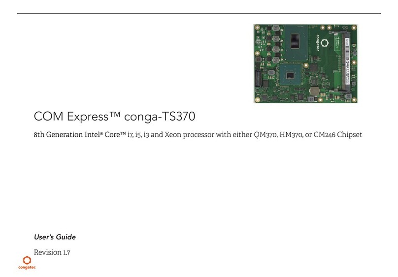
Table 11 Memory Population Compatibility........................................... 45
Table 12 Signal Tables Terminology Descriptions .................................. 46
Table 13 Connector A-B Pinout.............................................................. 47
Table 14 Connector C-D Pinout ............................................................. 49
Table 15 PCI Express Signal Descriptions (general purpose) ................. 51
Table 16 PCI Express Signal Descriptions (x16 Graphics)....................... 52
Table 17 DDI Signal Description............................................................. 54
Table 18 TMDS Signal Descriptions ....................................................... 55
Table 19 DisplayPort (DP) Signal Descriptions ....................................... 57
Table 20 Embedded DisplayPort Signal Descriptions............................ 58
Table 21 CRT Signal Descriptions........................................................... 59
Table 22 LVDS Signal Descriptions......................................................... 59
Table 23 Serial ATA Signal Descriptions................................................. 60
Table 24 USB 2. 0 Signal Descriptions.................................................... 60
Table 25 USB 3.0 Signal Descriptions..................................................... 61
Table 26 Gigabit Ethernet Signal Descriptions....................................... 62
Table 27 High Definition Audio Link Signals Descriptions ..................... 63
Table 28 LPC Signal Descriptions........................................................... 63
Table 29 SPI BIOS Flash Interface Signal Descriptions........................... 64
Table 30 Miscellaneous Signal Descriptions........................................... 64
Table 31 General Purpose I/O Signal Descriptions ................................ 65
Table 32 Power and System Management Signal Descriptions ............. 65
Table 33 Rapid Shutdown Signal Descriptions....................................... 66
Table 34 Thermal Protection Signal Descriptions................................... 66
Table 35 SMBus Signal Description........................................................ 66
Table 36 General Purpose Serial Interface Signal Descriptions.............. 67
Table 37 Module Type Definition Signal Description ............................. 67
Table 38 Power and GND Signal Descriptions....................................... 68
Table 39 Bootstrap Signal Descriptions.................................................. 69

Copyright © 2022 congatec GmbH TSTLm01 11/72
1 Introduction
1.1 COM Express™ Concept
COM Express™ is an open industry standard defined specifically for COMs (computer on modules). Its creation makes it possible to smoothly
transition from legacy interfaces to the newest technologies available today. COM Express™ modules are available in following form factors:
•Mini 84 mm x 55 mm
•Compact 95 mm x 95 mm
•Basic 125 mm x 95 mm
•Extended 155 mm x 110 mm
Table 1 COM Express™ 3.0 Pinout Types
Types Connector
Rows
PCIe Lanes PEG SATA Ports LAN ports USB 2.0/
SuperSpeed USB
Display Interfaces
Type 6 A-B C-D Up to 24 1 Up to 4 1 Up to 8 / 4 1VGA,LVDS/eDP, PEG, 3x DDI
Type 7 A-B C-D Up to 32 - Up to 2 5 (1x 1 Gb, 4x 10 Gb) Up to 4 / 4
Type 10 A-B Up to 4 - Up to 2 1 Up to 8 / 2 1LVDS/eDP, 1xDDI
1. The SuperSpeed USB ports (USB 3.0) are not in addition to the USB 2.0 ports. Up to 4 of the USB 2.0 ports can support SuperSpeed USB.
The conga-TS570 modules use the Type 6 pinout definition and comply with COM Express 3.0 specification. They are equipped with two high
performance connectors that ensure stable data throughput.
The COM (computer on module) integrates all the core components and is mounted onto an application specific carrier board. COM modules
are legacy-free design (no Super I/O, PS/2 keyboard and mouse) and provide most of the functional requirements for any application. These
functions include, but are not limited to a rich complement of contemporary high bandwidth serial interfaces such as PCI Express, Serial ATA,
USB 2.0, and Gigabit Ethernet. The Type 6 pinout provides the ability to offer PCI Express, Serial ATA, and LPC options thereby expanding
the range of potential peripherals. The robust thermal and mechanical concept, combined with extended power-management capabilities, is
perfectly suited for all applications.
Carrier board designers can use as little or as many of the I/O interfaces as deemed necessary. The carrier board can therefore provide all
the interface connectors required to attach the system to the application specific peripherals. This versatility allows the designer to create a
dense and optimized package, which results in a more reliable product while simplifying system integration. Most importantly, COM Express™
modules are scalable, which means once an application has been created there is the ability to diversify the product range through the use
of different performance class or form factor size modules. Simply unplug one module and replace it with another; no redesign is necessary.

Copyright © 2022 congatec GmbH TSTLm01 12/72
1.2 Options Information
The conga-TS570 is currently available in 10 variants (seven commercial and three industrial). The table below shows the different configurations
available.
Table 2 Commercial Variants
Part-No. 050700 050701 050702 050703
Processor Intel®Core™ i7-11850HE
2.6 GHz, 8 Core™
Intel®Core™ i5-11500HE
2.6 GHz, 6 Core™
Intel®Core™ i3-11100HE
2.4 GHz, 4 Core™
Intel®Celeron®6600HE
2.6 GHz, 2 Core™
Intel®Smart Cache 24 MB 12 MB 8 MB 8 MB
Max. Turbo Frequency 4.7 GHz 4.5 GHz 4.4 GHz N.A
Chipset QM580E QM580E HM570E HM570E
Processor Graphics Intel®UHD Graphics
(with 32 EU)
Intel®UHD Graphics
(with 32 EU)
Intel®UHD Graphics
(with 16 EU)
Intel®UHD Graphics
(with 16 EU)
GFX Base/Max. Dynamic Freq. 0.35/1.35 GHz 0.35/1.35 GHz 0.35/1.25 GHz 0.35/1.10 GHz
DDR4 Memory
(ECC or non-ECC)
3200 MTps dual channel
Non-ECC
3200 MTps dual channel
Non-ECC
3200 MTps dual channel
Non-ECC
3200 MTps dual channel
Non-ECC
Ethernet Controller Intel®I225-LM Intel®I225-LM Intel®I225-V Intel®I225-V
Intel®TSN/TCC TSN TSN N.A N.A
Processor TDP (cTDP down) 45 (35) W 45 (35) W 45 (35) W 35 W
Compatible Carrier Board conga-TEVAL/COMe 3.0 Evaluation Carrier Board for COM Express Type 6 modules
Part-No. 050713 050714 050715
Processor Intel®Xeon®W-11865MLE
1.5 GHz, 8 Core™
Intel®Xeon®W-11555MLE
1.9 GHz, 6 Core™
Intel®Xeon®W-11155MLE
1.8 GHz, 4 Core™
Intel®Smart Cache 24 MB 12 MB 8 MB
Max. Turbo Frequency 4.5 GHz 4.4 GHz 3.1 GHz
Chipset RM590E RM590E RM590E
Processor Graphics Intel®UHD Graphics
(with 32 EU)
Intel®UHD Graphics
(with 32 EU)
Intel®UHD Graphics
(with 16 EU)
GFX Base/Max. Dynamic Freq. 0.35/1.35 GHz 0.35/1.35 GHz 0.35/1.25 GHz
DDR4 Memory
(ECC or non-ECC)
3200 MTps dual channel
ECC or non-ECC
3200 MTps dual channel
ECC or non-ECC
3200 MTps dual channel
ECC or non-ECC
Ethernet Controller Intel®I225-IT Intel®I225-IT Intel®I225-IT
Intel®TSN/TCC TSN/TCC TSN/TCC TSN/TCC
Processor TDP (cTDP down) 25 W 25 W 25 W
Compatible Carrier Board conga-TEVAL/COMe 3.0 Evaluation Carrier Board for COM Express Type 6 modules

Copyright © 2022 congatec GmbH TSTLm01 13/72
Table 3 Industrial Variants
Part-No. 050710 050711 050712
Processor Intel®Xeon®W-11865MRE
2.6 GHz, 8 Core™
Intel®Xeon®W-11555MRE
2.6 GHz, 6 Core™
Intel®Xeon®W-11155MRE
2.4 GHz, 4 Core™
Intel®Smart Cache 24 MB 12 MB 8 MB
Max. Turbo Frequency 4.7 GHz 4.5 GHz 4.4 GHz
Chipset RM590E RM590E RM590E
Processor Graphics Intel®UHD Graphics
(with 32 EU)
Intel®UHD Graphics
(with 32 EU)
Intel®UHD Graphics
(with 16 EU)
GFX Base/Max. Dynamic Freq. 0.35/1.35 GHz 0.35/1.35 GHz 0.35/1.25 GHz
DDR4 Memory
(ECC or non-ECC)
3200 MTps dual channel
ECC or non-ECC
3200 MTps dual channel
ECC or non-ECC
3200 MTps dual channel
ECC or non-ECC
Ethernet Controller Intel®I225-IT Intel®I225-IT Intel®I225-IT
Intel®TSN/TCC TSN/TCC TSN/TCC TSN/TCC
Processor TDP (cTDP down) 45 (35) W 45 (35) W 45 (35) W
Compatible Carrier Board conga-TEVAL/COMe 3.0 Evaluation Carrier Board for COM Express Type 6 modules

Copyright © 2022 congatec GmbH TSTLm01 14/72
2 Specifications
2.1 Feature List
Table 4 Feature Summary
Form Factor Based on COM Express™ standard pinout Type 6 Rev. 3.0 (Basic size: 125 mm x 95 mm)
Processor 11th Generation Intel®Core i7,i5,i3, Celeron and Xeon H-processors
Memory Up to three memory sockets (located on the top and bottom side of the conga-TS570). Supports
-SO-DIMM ECC 1or non-ECC DDR4 modules 2
-Data rates up to 3200 MT/s
-Maximum 96 GB capacity (32 GB each)
Chipset Intel®500 Series Chipset QM580E, HM570E 3and RM590E PCH
Audio High definition audio interface with support for multiple codecs
Ethernet Intel®i225-LM/V/IT 2.5 GbE controller with support for TSN
Graphics Options Intel® Iris®Xe(Gen. 12). Supports:
-API (DirectX 12, Direct3D 12, Direct3D 2015, OpenGL 4.5, OpenCL 2.2)
-Intel®QuickSync & Clear Video Technology HD (hardware accelerated video decode/encode/processing/transcode)
-Up to four independent displays (see table 10 “Display Combination and Resolution”)
3x DP++
1x LVDS/eDP 4
1x VGA 5
1x PEG Gen 4 port (x16 lanes)
Resolutions up to 4x4k @ 60 Hz
NOTE:
The conga-TS570 does not natively support TMDS. For TMDS support, a DP++
to TMDS converter (e.g. PTN3360D) needs to be implemented on the carrier
board.
Peripheral
Interfaces
8x USB 2.0 (Up to 4x USB 3.2 Gen 2x1)
4x SATA®6 Gbps (with RAID 0/1/5/10 support)
8x PCI Express®Gen. 3 lanes
1x Optional onboard NVMe SSD (PCIe x4 Gen 4)
2x UART (16C550 compatible)
GPIOs
LPC/eSPI 6
I²C (fast mode, multi-master)
SMB
SPI
BIOS AMI Aptio®V UEFI 2.6 firmware
32 MB serial SPI flash with congatec Embedded BIOS features
Power
Management
ACPI 5.0a compliant with battery support.
S5e mode (see section 6.1.7 “Enhanced Soft-Off State”)
Deep Sx and Suspend to RAM (S3)
Configurable TDP
congatec Board
Controller
Multi-stage watchdog, non-volatile user data storage, manufacturing and board information, board statistics, hardware monitoring, fan control, I²C
bus, power loss control
Security Discrete SPI Trusted Platform Module (Infineon SLB9670_VQ2.0); AES Instructions

Copyright © 2022 congatec GmbH TSTLm01 15/72
Note
1. Only variants that feature the Intel RM590E support ECC memory.
2. See section 7.6 “SoDIMM Population Rules” for a list of memory population rules.
3. Variants with Intel HM570E chipset do not support Intel VPro/AMT Technology.
4. Both interfaces are not supported at the same time.
5. Default on commercial variants; assembly option on industrial variants.
6. The conga-TS570 does not currently support eSPI interface.
Caution
The conga-TS570 will not boot if the top, upper slot is not populated in a dual memory configuration. See section 7.5 “SoDIMM Population
Rules” for more information.
2.2 Supported Operating Systems
The conga-TS570 supports the following operating systems.
•Microsoft®Windows® 10 (64-bit)
•Microsoft®Windows® 10 IoT Enterprise (64-bit)
•Linux (64-bit)
•Yocto
•Real Time Systems Hypervisor
Note
1. The conga-TS570 supports only native UEFI Operating Systems. Legacy Operating Systems which require CSM (Compatibility Suppport
Module) as part of the UEFI firmware are not supported anymore.
2. For Windows 10 installation, we recommend a minimum storage capacity of 20 GB. congatec will not offer technical support for systems
with less than 20 GB storage space.

Copyright © 2022 congatec GmbH TSTLm01 16/72
2.3 Mechanical Dimensions
•Length of 125 mm
•Width of 95 mm
The overall height of the heatspreader is shown below:
2.4 Supply Voltage Standard Power
•12V DC ± 5%
The dynamic range shall not exceed the static range.
Heatspreader
All dimensions in millimeter
Module PCB
Carrier Board PCB
13.00
5.00 or 8.00
4.00
5.00
4.50
2.00±10%
7.00
Nominal Static Range
Dynamic Range
Absolute Minimum
Absolute Maximum12.60V
11.40V
12V
12.10V
11.90V

Copyright © 2022 congatec GmbH TSTLm01 17/72
2.4.1 Electrical Characteristics
Power supply pins on the module’s connectors limit the amount of input power. The following table provides an overview of the limitations for
pinout Type 6 (dual connector, 440 pins).
Power Rail Module Pin
Current Capability
(Ampere)
Nominal
Input
(Volts)
Input
Range
(Volts)
Derated
Input
(Volts)
Max. Input Ripple
(10 Hz to 20 MHz)
(mV)
Max. Module Input
Power (w. derated input)
(Watts)
Assumed
Conversion
Efficiency
Max. Load
Power
(Watts)
VCC_12V 12 12 11.4-12.6 11.4 +/- 100 137 85% 116
VCC_5V-SBY 2 5 4.75-5.25 4.75 +/- 50 9
VCC_RTC 0.5 3 2.5-3.3 +/- 20
2.4.2 Rise Time
The input voltages shall rise from 10% of nominal to 90% of nominal at a minimum slope of 250 V/s. The smooth turn-on requires that, during
the 10% to 90% portion of the rise time, the slope of the turn-on waveform must be positive.
2.5 Power Consumption
The power consumption values were measured with the following setup:
•conga-TS570 COM
•modified congatec carrier board
•conga-TS570 cooling solution
•Microsoft Windows 10 (64 bit)
Note
The CPU was stressed to its maximum workload with the Intel®Thermal Analysis Tool

Copyright © 2022 congatec GmbH TSTLm01 18/72
Table 5 Measurement Description
The power consumption values were recorded during the following system states:
System State Description Comment
S0: Minimum value Lowest frequency mode (LFM) with minimum core voltage during desktop idle
S0: Maximum value Highest frequency mode (HFM/Turbo Boost) The CPU was stressed to its maximum frequency
S0: Peak current Highest current spike during the measurement of “S0: Maximum value”. This
state shows the peak value during runtime
Consider this value when designing the system’s power supply to
ensure that sufficient power is supplied during worst case scenarios
S3 COM is powered by VCC_5V_SBY
S5 COM is powered by VCC_5V_SBY
S5e COM is powered by VCC_5V_SBY
Note
1. The fan and SATA drives were powered externally.
2. All other peripherals except the LCD monitor were disconnected before measurement.
Table 6 Power Consumption Values
The table below provides additional information about the conga-TS570 power consumption. The values were recorded at various operating
mode.
Part
No.
Memory
Size
H.W
Rev.
BIOS
Rev.
OS
(64 bit)
CPU Current (Ampere)
Variant Cores Freq. /Turbo
(GHz)
S0:
Min
S0:
Max
S0:
Peak
S3 S5 S5e
050700 2 x 4 GB TBD TBD Windows 10 Intel®Core™ i7-11850HE 8 2.6 / 4.7 TBD TBD TBD TBD TBD TBD
050701 2 x 4 GB TBD TBD Windows 10 Intel®Core™ i5-11500HE 6 2.6 / 4.5 TBD TBD TBD TBD TBD TBD
050702 2 x 4 GB TBD TBD Windows 10 Intel®Core™ i3-11100HE 4 2.4 / 4.4 TBD TBD TBD TBD TBD TBD
050703 2 x 4 GB TBD TBD Windows 10 Intel®Celeron®6600HE 2 2.6 / N.A TBD TBD TBD TBD TBD TBD
050710 2 x 4 GB TBD TBD Windows 10 Intel®Xeon®W-11865MRE 8 2.6 / 4.7 TBD TBD TBD TBD TBD TBD
050711 2 x 4 GB TBD TBD Windows 10 Intel®Xeon®W-11555MRE 6 2.6 / 4.5 TBD TBD TBD TBD TBD TBD
050712 2 x 4 GB TBD TBD Windows 10 Intel®Xeon®W-11155MRE 4 2.4 / 4.4 TBD TBD TBD TBD TBD TBD
050713 2 x 4 GB TBD TBD Windows 10 Intel®Xeon®W-11865MLE 8 1.5 / 4.5 TBD TBD TBD TBD TBD TBD
050714 2 x 4 GB TBD TBD Windows 10 Intel®Xeon®W-11555MLE 6 1.9 / 4.4 TBD TBD TBD TBD TBD TBD
050715 2 x 4 GB TBD TBD Windows 10 Intel®Xeon®W-11155MLE 4 1.8 / 3.1 TBD TBD TBD TBD TBD TBD
Note
With fast input voltage rise time, the inrush current may exceed the measured peak current.

Copyright © 2022 congatec GmbH TSTLm01 19/72
2.6 Supply Voltage Battery Power
Table 7 CMOS Battery Power Consumption
RTC @ Voltage Current
-10oC 3V DC TBD
20oC 3V DC TBD
70oC 3V DC TBD
Note
1. Do not use the CMOS battery power consumption values listed above to calculate CMOS battery lifetime.
2. Measure the CMOS battery power consumption of your application in worst case conditions (for example, during high temperature and
high battery voltage).
3. Consider the self-discharge of the battery when calculating the lifetime of the CMOS battery. For more information, refer to application
note AN9_RTC_Battery_Lifetime.pdf on congatec GmbH website at www.congatec.com/support/application-notes.
4. We recommend to always have a CMOS battery present when operating the conga-TS570.
2.7 Environmental Specifications
Temperature (commercial variants) Operation: 0° to 60°C Storage: -20° to 80°C
Temperature (industrial variants) Operation: -40° to 85°C Storage: -40° to 85°C (up to 1 Gb Ethernet)
Temperature (industrial variants) Operation: -40° to 70°C Storage: -40° to 85°C (up to 2.5 Gb Ethernet)
Humidity Operation: 10% to 90% Storage: 5% to 95%
Caution
The above operating temperatures must be strictly adhered to at all times. When using a congatec heatspreader, the maximum operating
temperature refers to any measurable spot on the heatspreader’s surface.
Humidity specifications are for non-condensing conditions.

Copyright © 2022 congatec GmbH TSTLm01 20/72
3 Block Diagram
11
th
Gen. Intel
®
Core
™
Intel
®
Celeron
Intel
®
Xeon
®
“Tiger Lake”
Processor
Mobile
Intel
®PCH-H
QM580E Series
for Intel
®
Core
™
Processors
HM570E Series
for Intel
®
Celeron
®
Processors
CM246 Series
for Intel
®
Xeon
®
E Processor
PECI
PCIe Gen. 4
PCIe Gen. 4
eDP
DDR4
DDIB
DDI TCP0
DDI TCP1
DDI TCP2
PECI SM Bus
PCIe Gen. 3
eSPI
SATA 6G
PCIe
USB 2.0
USB 3.1
HDA
SPI0
MGMNT
DMI Gen3
conga-TS570
COM Express Rev. 3.0, Basic Size, Type 6 Pinout
Dual Channel DDR4
SO-DIMM
ECC / non ECC
SPI Flash 0 TPM 2.0
Ethernet 10/100/1000/2500
Intel i225-LM/V/IT
eDP to LVDS
congatec
Board
Controller
5th Generation
GPIOs
eSPI
SMBSMB
UART
I2C
LID/SLEEP/FAN
DP to VGA
x4 NVMe SSD
MUX MUX
Ethernet
SPI
VGA
LVDS/eDP
LPC
SM Bus
HDA I/F
I2C Bus
USB 2.0 Ports 0 - 7
SATA Ports 0 - 3
SER0/1
GPIOs (8x)
LID# / SLEEP# / FAN
PCIe lanes 0 - 7
USB 3.1 Gen 2 Ports 0 - 3
PEG x16
DP++ (DDI3)
DP++ (DDI2)
DP++ (DDI1)
eSPI to LPC
This manual suits for next models
10
Table of contents
Other Congatec Single Board Computer manuals

Congatec
Congatec conga-SMX8 User manual

Congatec
Congatec Com Express conga-TC570 User manual

Congatec
Congatec conga-IC370 User manual

Congatec
Congatec conga-JC370 User manual

Congatec
Congatec conga-STDA4 User manual

Congatec
Congatec COM Express conga-TS87 Series User manual

Congatec
Congatec COM Express conga-TC570r User manual

Congatec
Congatec COM Express conga-TS370 User manual