Connect2Car ANYWHERE GSM KIT User manual

Installation Manual
Connect2Car Anywhere GSM Kit
www.connect2car.com
ANYWHERE GSM KIT
INSTALLATION MANUAL (REV E)

Installation Manual
Connect2Car Anywhere GSM Kit
www.connect2car.com
2
1. DISCLAIMER ...............................................................................................................................4
1.1. COPYRIGHT ..........................................................................................................................................................................4
1.2. SAFETY ISSUES ....................................................................................................................................................................4
2. SYSTEMS OVERVIEW: ................................................................................................................5
2.1. About the Connect2Car Anywhere Hardware Device ...............................................................................................5
2.1.1. Other optional hardware that might be needed for Installation.......................................................................6
2.1.1.1. Remote Starter or Remote Starter and Alarm System .................................................................................... 6
2.1.1.2. Ignition Bypass Kit ....................................................................................................................................................6
2.1.1.3. Data Link Interface kit /CAN Bus ............................................................................................................................6
2.2. About the Software Controller .......................................................................................................................................8
2.2.1. COMPATIBLE PHONES ................................................................................................................................................. 8
2.3. About the web controller interface ..............................................................................................................................9
2.4. The Text Message Control Interface ...........................................................................................................................10
2.5. How it works......................................................................................................................................................................12
3. INSTALLATION CONSIDERATIONS:..........................................................................................13
4. MOUNTING THE MODULE:.......................................................................................................13
5. MOUNTING THE ANTENNA:.....................................................................................................13
6. MOUNTING THE MICROPHONE (OPTIONAL):..........................................................................13
7. MOUNTING THE BACKUP BATTERY (IF INCLUDED): ..............................................................14
8. GENERAL WIRING DIAGRAM ....................................................................................................15
9. GUIDELINE OF SYSTEM FEATURES TO INSTALL. ...................................................................16
10. INSTALLATION STEPS ..........................................................................................................16
11. WIRING DESCRIPTIONS ........................................................................................................18
11.1. Brown Wire GROUND WIRE (Pin16): .......................................................................................................................18
11.2. Red Wire POWER WIRE (Pin15):...............................................................................................................................18

Installation Manual
Connect2Car Anywhere GSM Kit
www.connect2car.com
3
11.3. Blue Wire (Pin13) / IGNITION INPUT WIRE: ...........................................................................................................18
11.4. Black/White Wire (Pin11) ENGINE ENABLE/DISABLE output (ALSO FOR FUEL CUTOFF OR ANY OTHER
KILL SWITCH: ...................................................................................................................................................................................19
11.5. Red/White Wire (Pin9) REMOTE START/STOP ACTIVATION output: ............................................................... 21
11.6. Yellow/White Wire (Pin7) Arm/Lock output (-100ma): .....................................................................................21
11.7. Brown/White Wire (Pin5) Disarm/Unlock output (-100ma):.............................................................................21
11.8. White Wire / ARM TRIGGER WIRE (Pin12) input (+ve): ......................................................................................22
11.9. Gray/Ash Wire / DISARM TRIGGER WIRE (Pin10) input (+ve):...........................................................................22
11.10. Yellow Wire (Pin8) Door, Hood and Trunk Trigger input (+ve):......................................................................23
11.11. Black Wire (Pin6) the Alarm Trigger wire input (+ve):......................................................................................23
11.12. Purple Wire (Pin4) Battery level Monitor wire:...................................................................................................23
11.13. Orange Wire (Pin2) Tachometer wire (optional): ...............................................................................................24
11.14. Green Wire Zimi Proximity Detect Wire (Pin14):................................................................................................24
11.15. Green/White Wire NOT CONNECTED (Pin3): ........................................................................................................ 24
11.16. Orange/White Wire NOT CONNECTED (Pin 1): .....................................................................................................24
12. GENERAL SPECIFICATIONS OF CONNECT2CAR GSM KIT ....................................................25
Instructions on how to use or operate this device may be found in the operations manual.
This manual explains the installation and connection of this unit including its interface with an
existing remote start/security alarm system.
It is recommended that you read these simple guidelines carefully before use, in order to ensure
the safe operation of the module.
This unitshould be installed by a professional automotive electronics installer.

Installation Manual
Connect2Car Anywhere GSM Kit
www.connect2car.com
4
1. DISCLAIMER
The information contained in this document is accurate at time of release. However, as Connect2Car Inc, is
committed to continued research and development activities, these specifications may change from time to time.
The present manual by Connect2Car Inc reflects the present state of the art of the products described therein. We
have endeavored to give a description that is as complete and clear as possible in order to make work with our
products as easy as possible for you. All the same, the manual may contain technical inaccuracies and typing errors.
As a result of the rapid advance in the art, we must also reserve the right to incorporate technical alterations and
developments without separate advance notice. That is why Connect2Car Inc, does not give any warranty for the
contents of the manual and for its continuing applicability. Nor is Connect2Car Inc. liable for any loss that might
result from consultation of this manual. Particularly, Connect2Car Inc is not liable for damage, nor indirect damage
(including damage that caused any financial loss, and similar consequences), arising from the use or improper use
of this manual, not even in the case where it was pointed out to Connect2Car Inc. or an agent of Connect2Car Inc.
that such damage might be sustained. Contact your Connect2Car representative, should you require clarification on
information contained in this document or to request of copy of the latest version of this document. You can also
visit www.connect2car.com for all the latest information/product manuals and documentation.
1.1. COPYRIGHT
The Connect2Car ANYWHERE GSM kit Installation Manual is copyright of Connect2Car Inc. with all rights reserved.
No part of this manual may be reproduced in any form without the prior written approval of Connect2Car Inc.
1.2. SAFETY ISSUES
It is recommended that you read these simple guidelines carefully before use, to ensure the safe operation of the
module. The ANYWHERE GSM kit should be installed by a professional automotive electronics installer.
Connect2Car, Inc. CANNOT VALIDATE NOR ENSURE THAT ANY OR ALL SAFETY REQUIREMENTS ARE MET DURING
INSTALLATION AND THEREFORE ACCEPTS NO RESPONSIBILTY FOR THE INSTALLATION OR LOSS CAUSED BYTHE
INSTALLATION OR USE OF THE ANYWHERE G2 AND THE ANYWHERE SOFTWARE INTERFACE.

Installation Manual
Connect2Car Anywhere GSM Kit
www.connect2car.com
5
2. SYSTEMS OVERVIEW:
2.1. About the Connect2Car Anywhere Hardware Device
The ANYWHERE GSM KIT is specially designed to interface with any vehicle to instantly empower Remote
Control of the Vehicle conveniently with a mobile phone as well as Remote tracking/monitoring. The hardware
utilizes any available GSM network to communicate with the controlling master (owner) as well as the Connect2Car
data logging server.
Figure 1Connect2Car Anywhere unit
Figure 2Connect2Car ANYWHERE kit
Main Unit
GPS and GSM
antenna
16pin connector for
electrical wiring to
vehicle. (16pin cable also
included)
Speaker and
microphone cable
connector.

Installation Manual
Connect2Car Anywhere GSM Kit
www.connect2car.com
6
2.1.1. Other optional hardware that might be needed for Installation
2.1.1.1.Remote Starter or Remote Starter and Alarm System
The Connect2Car unit works with any existing alarm installation in the vehicle. E.g. the Connect2Car system
can be connected to monitor the Alarm siren output to notify user of Alarm status. It also will interface with
factory lock/unlock; arm/disarm interface and also any remote starter system with a remote start trigger
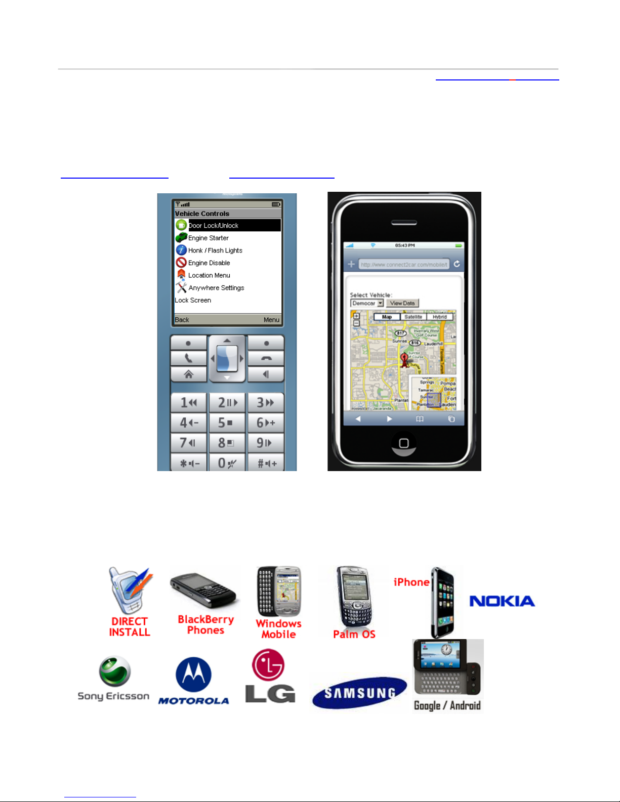
interface. This also enables user to have dual control of the vehicle either locally when in range via Key Fob, or
remotely (Anywhere) via phone (when out of traditional keyfob range).
Some Compatible Alarms and Remote Starter Systems include:
Most Factory Alarm Systems
Viper Alarm Systems (DEI alarms)
CompuStar Alarm Systems
Omega Alarm systems
Any Remote Starter that has a Remote Trigger Interface.
For vehicles without an already existing alarm system, the Connect2Car unit is all you need, as it provides all the
typical alarm/security functions from unlimited range.
2.1.1.2.Ignition Bypass Kit
This module is usually needed when installing with a Remote starter. In newer vehicles today, usually 1996 and
newer for USA vehicles, they come with an anti-theft feature that prevents starting of vehicle without coded key
positioned in the ignition key cylinder. While a great feature for anti-theft, it usually restricts the Remote Starter
from starting the vehicle when Key is not detected.
Ignition bypass kits are needed to bypass the feature when the Remote Starter needs to engage the starting
system of the vehicle. Please contact Connect2Car support for more information or guide of selection of bypass
units for a specific vehicle. Sometimes the Data Link Interface unit, described below, usually comes combined with
an Ignition Bypass feature also. See
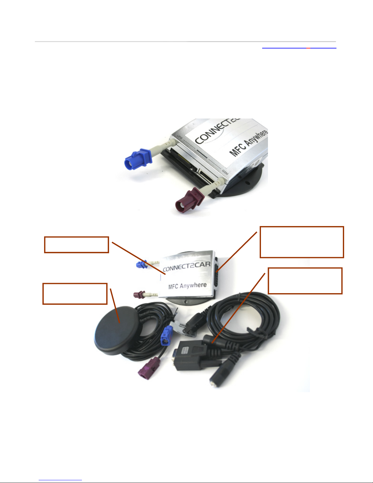
2.1.1.3.Data Link Interface kit /CAN Bus
What is an Interface Kit?
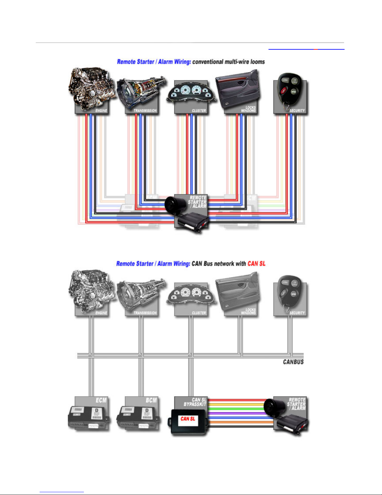
Traditionally after-market installations on multi-loom wired vehicles required the installer to make an electrical
connection for each function. With the modern multiplexed systems and computer networks, an interface unit
makes it possible to connect multi-loom after-market electronics into networked vehicle systems. Not only does an
interface kit make the installation possible, but it also decreases the installation time, which increases dealer
profits. Visit http://www.connect2car.com/store/ for more details.

Installation Manual
Connect2Car Anywhere GSM Kit
www.connect2car.com
7
Figure 3In traditional Installation, connections are made individually to all components
Figure 4The Data interface Kit simplifies Installation by utilizing the factory data bus

Installation Manual
Connect2Car Anywhere GSM Kit
www.connect2car.com
8
2.2. About the Software Controller
Once the kit is installed in the vehicle, it can then be controlled using the ANYWHERE software which is
installed on any java supporting mobile phone. This software makes it possible for the user to issue commands to
the vehicle and as well receive messages from the vehicle. The ANYWHERE software is a highly user friendly and
therefore very easy to use. Get the latest ANYWHERE software for your phone by pointing your mobile browser to
connect2car.com/mobile.Also see the Anywhere software page for more details.
Figure 5Vehicle Controls on a Phone (left), Mapping vehicle from a phone (right)
2.2.1. COMPATIBLE PHONES
The software is available for most phones, and currently tested and trusted for Nokia, Ericsson, Motorola,
Samsung, Blackberry (all series), Pocket PC’s and Window Mobile Phones (all series),Palm OS phones (all series)
Apple iPhone and all other java enabled phones. Some phones might require loading of a Java application
Manager if not already preinstalled on the device. Connect2Car maintains an active online support forum,
phone line and email to aid with any installation issues.

Installation Manual
Connect2Car Anywhere GSM Kit
www.connect2car.com
9
2.3. About the web controller interface
The Connect2Car ANYWHERE can also be controlled from the web controller interface if the user has access
to an internet enabled computer or device. Simply visit www.anywheretracking.com and log in with your
account credentials. Your account information is provided when you register your device unto the
connect2car server. To register a new device you can easily visit www.connect2car.com/track and sign up a
new device. From the web control panel you can perform all the same functions you perform on your phone
as well as perform other administrative duties for your account such as history reports, SMS alarm settings
etc.

Installation Manual
Connect2Car Anywhere GSM Kit
www.connect2car.com
10
2.4. The Text Message Control Interface
The unit can also be controlled by sending a text message from the Authorized phone number to the units
assigned phone number.
•The units assigned phone number is provided to you upon activation of your device if you are using a
Connect2Car assigned SIM card. If you are using this unit with your own GSM sim card, the assigned
phone number is the phone number of the SIM card you place in the unit.
•The Authorized phone number is the number you provided to Connect2Car upon purchase of your unit.
To change the authorized phone number on your unit account, email support@connect2car.com or call
the support line at 914-239-3826
To control the unit, send a text message to the assigned phone number using the reference below. E.g to
lock the door, text Lock to the assigned number. The commands are case sensitive and they only work when sent
from the authorized phone number. You can cut out the card below and keep it handy for reference:
New commands: Software 2_13 and up or units purchased after 02/30/2009.
Arm - Arms the unit without locking the doors.
Disarm – Disarms the unit without locking the doors.

Installation Manual
Connect2Car Anywhere GSM Kit
www.connect2car.com
11
Connect2Car Anywhere Software on a Mobile Device.

Installation Manual
Connect2Car Anywhere GSM Kit
www.connect2car.com
12
2.5. How it works
The ANYWHERE GSM KIT is simply a GSM based communication device that interfaces with the vehicle hardware
controls like an alarm system. It has an onboard GPS unit to obtain precise GPS location information. It maintains
two way communication between the owner and the vehicle to give up to date status of the vehicle.
Whenever the user sends a command, this command is sent to the receiver unit in the vehicle via GSM
networks. This command is automatically interpreted and executed accordingly. For example the user clicks a
button to unlock the doors. This message travels over the GSM networksto the receiver unit within the vehicle.
This message is interpreted immediately and the outcome is unlocking of the vehicle doors. Same thing implies in a
situation where an event occurs in the vehicle. For example, someone opens the hood of a monitored vehicle. The
signal is transmitted directly to the device within the vehicle and the device automatically sends a specific SMS to
the specified mobile phone numbers with information showing that the hood has just been opened.
All commands received by the vehicle, are confirmed with a reply from the unit. Furthermore, for users
registered on the Connect2Car service, a copy of all activity is sent to the Connect2Car server for history logging
and post analysis support purposes. The user can also command the vehicle from the Connect2Car track website
(www.connect2car.com/track). Connect2Car maintains active IP servers that interact with users and vehicles.
These servers offer this continuous service over an IP network for mobile data connected devices (e.g. users cell
phone with data network), and also an SMS to IP gateway server for devices with an SMS only connection.
For the text interface, the Connect2Car unit responds only to authorize users identified via a designated phone
number.For the data/gprs/internet mode, the unit responds to any authorized user with the correct account login
credentials assigned to the vehicle.
In a situation whereby a master user misplaces or loses his/her mobile phone, the master phone # can be
disabled via the website interface to prevent unauthorized persons from having access to the vehicles control
system.Furthermore the software also employs a local password protected lockout. (This means, you need to know
the local password to access the software control interface on the phone). The access phone numbers on the
device can be changed from the website, or from the menu on the phone device, or also by calling the Connect2Car
phone operator at +1.914.239.3826 or emailing support@connect2car.com

Installation Manual
Connect2Car Anywhere GSM Kit
www.connect2car.com
13
3. INSTALLATION CONSIDERATIONS:
First thing to do: You are required to go through the entire contentsof this manual before the commencement of
installation. A good understanding of which control wires are to be used and their functions is essential.
4. Mounting the module:
The ANYWHERE GSM MODULE should be mounted in any well hidden location within the vehicle compartment. It is
very relevant to consider avoiding positions of extreme temperatures. Acceptable positions include: behind the
dash board and behind the glove box, under the rear seat, behind rear seat, behind radio etc. Use the unit
mounting holes to fasten the unit into a fixed position. You can use small fastening screws or a plastic tie wrap to
secure unit.
Figure 6Main Unit
5. Mounting the Antenna:
The antenna encloses both the GSM and GPS receivers. The antenna is highly sensitive and should as much as
possible be mounted in a position that is stealth but not covered from the sky (for best GPS reception). Its
reception is highly affected by metallic shielding. Therefore avoid any location that permits any metallic covering.
Acceptable positions include behind the dash board (plastic and fiber covering does not affect the reception) or
behind the back seat but not within the hood or engine compartment.
Mounting in a visible location such as right on top of the dashboard/windscreen is not recommended if security
is the main reason for the installation. Such a location compromises the antenna in the event of a security break in.
Figure 7GPS and GSM antenna
6. Mounting the Microphone (optional):
If you purchased the audio microphone input connector as well as a speaker output connection. Any standard
microphone can suitably be connected to the microphone input of the unit to listen in on conversations in the
vehicle as well as communicate via voice to the vehicle from the speaker output connection (speaker and mic not
included). This can also be used as a speaker phone for the vehicle. The unit also has a GPS serial port output that
can be used as a standalone GPS input for turn by turn GPS navigation software tool in the vehicle.
GPS and GSM
receiver. Sticky pad
underside for easy
mounting.
Connections to the
Connect2Car
ANYWHERE device.

Installation Manual
Connect2Car Anywhere GSM Kit
www.connect2car.com
14
The audio microphone should be mounted in a good location where it can properly pick voice signals within the
vehicle. It should not be too exposed and at the same time should not be hidden, instead it should be disguised
somewhere in a central location within the vehicle. E.g. dashboard, behind the back seat mid way between the two
speakers (this location is usually affected by the speakers if the sound system is on). Make sure the microphone is
properly insulated from grounding on the vehicle chassis.
Figure 8Microphone, Speaker and GPS output connectors
7. Mounting the backup Battery (if included):
The unit already comes with an internal backup battery that keeps the unit running even when external power has
been disconnected. The run time depends on which controls are being used, but provides an average of 12-24 hrs of
back up power use.
On request, some of the Connect2Car kits also include an external backup battery. The backup battery
should be mounted at the same place with the device. This is in order to minimize energy losses due to resistance
of wire. Mounting in other locations far from the device is also possible but please make sure that connecting
terminal does not exceed 2m as this may lead to voltage drop and thereby low power supply to the device. Also
ensure that the battery is not exposed to extreme temperatures.
Speaker Output
connection
Connection to the
Connect2Car
Anywhere unit
Microphone input
connector
Serial GPS output
(optional)
Can be used for GPS
navigation software
in vehicle.

Installation Manual
Connect2Car Anywhere GSM Kit
www.connect2car.com
15
8. General wiring diagram
Figure 9General Wiring Diagram of Connect2Car Anywhere Unit with a Remote Starter Alarm

Installation Manual
Connect2Car Anywhere GSM Kit
www.connect2car.com
16
9. Guideline of system features to install.
The Connect2car Anywhere G2 kit can perform various functions depending on what your primary objective is.
Some people want the remote security operations of GPS tracking and disabling of the vehicle or the convenience
of remote control functions such as remote engine start, door lock/unlock, while some want all the features active.
The installation effort depends on the amount of features integrated. Below is a guideline of features for
installation integration.
10. INSTALLATION STEPS
Step 1: Locate all the wires needed for the connection and identify locations where you want to position
the unit and its accessories for install. Now decide what features you want to implement for your installation,
to know the amount of wires to connect.

Installation Manual
Connect2Car Anywhere GSM Kit
www.connect2car.com
17
Step 3: Position all the accessories in their most suitable positions and extend their wiresto the central
point where the device is to be mounted.
Step 4: Link the wires from the 16-pin connectors to their appropriate harnesses in the vehicle ensuring
that the connections are firm.(Don’t forget to insulate every wire connection properly). Follow the detailed
wire explanations further in the manual to get descriptive details of each wire function.
Step 5: Plug the GPS and the GSM antennas to the device. Power the device by plugging the 16-pin
connector on the device.
•The unit will initially flash a short 1sec green light, and then go off for about 2 minutes while the unit
boots up.
•After the unit is has booted up, a solid green LED will come on. Once the unit gets on the network
successfully the Green LED will start flashing. At this point a text message will be sent to the
Authorized phone number to indicate that the device is online.
•Once the unit picks up a GPS signal, it will start multiple flashes of red, orange and green. If the red or
orange LED does not come on, it means the unit is not getting a good GPS signal, so relocate the
antenna accordingly until you get a red/orange flash for valid GPS reception.
Step 6: To test the unit, you can either test from the internet account at www.connect2car.com/track or
using the TEXT INTERFACE described in section 2.4. Using the Text interface or the Connect2Car software on
your phone, you can send commands to the unit and check to see that each command executes properly. The
unit also replies confirmation of the commands via a text message alert to the user authorized phone, or an
email alert to the users email account. Your test depends on what features are installed (see installation
features, chapter 9 above)
•Test control features: Door lock/unlock, Remote Start/Stop, Engine kill disable/enable, Window
up/down(if installed)
•Test alert features: Alarm/Siren triggered when the unit is armed, should send alert to
phone/email. Door/trunk/hood opened when unit is armed should also send alert.
•Test GPS location features: Unit should update its current GPS location when ever an action
occurs, such as a command or alert or if you enable continuous location update. To view the
current location, either click the internet link that is given to you via the text interface reply, or
use the Connect2Car phone software or the web interface to view current GPS location of unit. To
request instant position, you can either send a POSITION REQUEST command using any of the
control interfaces.
Make sure the
included SIM card of
the unit is located
inside its holder
Connect the Blue GPS
connector here. Save
this for the last
connection.
Connect the Blue
GPS connector here.
Save this for the last
connection.
Follow instructions
on next Page for the
individual
connections on the
16pin connector.

Installation Manual
Connect2Car Anywhere GSM Kit
www.connect2car.com
18
Figure 10 The 16 Pin Connector
11. Wiring Descriptions
11.1.Brown Wire GROUND WIRE (Pin16):
This wire (brown)supplies negative ground to the Device. This terminal must be connected properly in
order to prevent malfunctioning of the system.
Connection:
The pin-16 terminal from the device should be connected to the metal frame of the vehicle using an
existing machine threaded fastener. In the absence of already exiting machine threaded fastener, make
sure this terminal is in firm contact with a bright clean metallic surface of the vehicle. Partial contact
should be avoided as much as possible. Insufficient ground connection may affect operation of the device.
11.2.Red Wire POWER WIRE (Pin15):
This is the main Power input to the device.
Connection:
The pin-15 terminal from the device should be connected to the battery’s positive terminal.
Remember to fuse this terminal with a 2A fuse. Avoid any moving part or hot surfaces.
HINT:
The positive wire can be found in the ignition harness of most vehicles. It
constantly reads +12V even when all accessories in the vehicle are switched off.
The unit can operate effectively from any power source within +10.8 V...+32.0V
The unit also automatically powers up once power is applied.
11.3.Blue Wire (Pin13) / IGNITION INPUT WIRE:
This wire (blue) is the ignition status monitoring terminal.
Connection:
The pin-13 terminal should be connected to the ignition terminal of the vehicle. This terminal is an ignition
“on” input to the device. Through this terminal the device receives a +12V signal when the ignition is on
and a negative ground signal when the ignition is off. The device monitors the ignition status of the vehicle
through this terminal.
Hint:
Refer to fig.4 below.

Installation Manual
Connect2Car Anywhere GSM Kit
www.connect2car.com
19
Figure 11 Wire test matrix for ignition wire
11.4. Black/White Wire (Pin11) ENGINE ENABLE/DISABLE output (ALSO
FOR FUEL CUTOFF OR ANY OTHER KILL SWITCH:
This wire (black/white) is the Engine disable wire.
Connection:
The pin-11 (black/white) terminal should be connected to a relay. This is an output terminal. This relay can
then be used to disable the electrical ignition to the vehicle and or the fuel pump power line, depending
on the level of security you are looking for. This wire will activate (with a –ve ground output 100ma) and
stay on continuously when triggered from the phone. The wire will become open when deactivated.
EXAMPLE 1: IGNITION DISABLE ONLY
Figure 12 Electrical Ignition disable Example

Installation Manual
Connect2Car Anywhere GSM Kit
www.connect2car.com
20
In this example the fuel cut/Engine disable wire is used to disable the electrical ignition of
the vehicle. This produces an instant disabling effect of a moving vehicle, since the engine shuts
down immediately and vehicle will not restart until the Engine is enabled by the
owner/controller.
EXAMPLE 2: FUEL PUMP DISABLE ONLY
Figure 13 Fuel Pump Disable
In this example, the fuel pump is power wire is disabled when the engine disable is activated.
Unlike the ignition disable which gives instant disabling of the vehicle, it might take a few seconds for the
vehicle to fully shut down due to lack of fuel flow. It makes the same effect as a vehicle running out of gas.
This option is not so necessary per say, but if vehicle theft is your ultimate threat, and then your installer
should take some time and enable/utilize this feature. A lot of would be car thieves know how to quickly
bypass a disabled ignition, but a fuel pump disable is very challenging and buys the vehicle recovery task
force enough time to corner in on the disabled vehicle.
EXAMPLE 3: FUEL PUMP AND IGNITION DISABLE (BEST METHOD)
Figure 14 Fuel and Engine Cut off Together
This is the ultimate/best way of wiring the cutoff output, whereby you cut off the electrical
ignition and fuel pump power line at the same time. Observe good installation practice of hiding the cutoff
relays far away from each other to reduce time to trace. Also improve the stealth of the installation by
using same color wires for the relay. This will ultimately waste any time spent in retracing the wires, while
the vehicle recovery task force e.g. police etc. homes in on disabled vehicle.
Table of contents