manuals.online logo
Brands
  1. Home
  2. •
  3. Brands
  4. •
  5. Consew
  6. •
  7. Sewing Machine
  8. •
  9. Consew 277RFS-3 Datasheet

Consew 277RFS-3 Datasheet

OP
RAT~ON
INSTRUCT~ON
&,
PARTS
l~ST
FOR
CONTENTS
i.Brief instruction...................·............................."......................................................................1
2.Main specifications.........................................."......................................................................1
3.Machine installation................................................................................................................1
4.lnstalling the motor
...........................................................................................,......................2
5.Connecting between the pedal and clutch lever..................................................................
..
S.lnstalling the presser foot lift control plate...............................................................................2
7.lnstalling the bobbin winder....................................................................................................3
8.1nstalling the thread stand.................."......" ...........................................................................3
9.0peration preparation............................"............................".................................................3
1
O.Lubrication.........................................................................................................,..................4
ii.Trial
running..........................................................." ....................................."......................4
12.lnsialling the needle....................."......................................................................................4
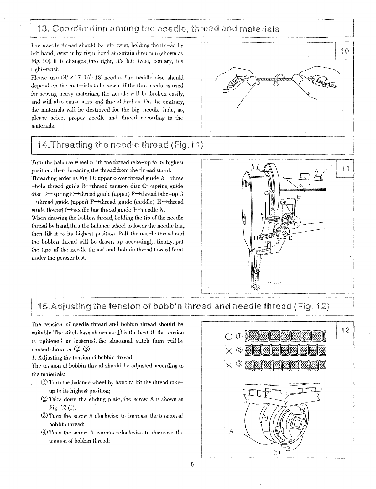
13.Coordination among the needle, thread and material.........................................................5
14.Threading the needle thread................................................................................................5
15.
Adjusting the tension of bobbin thread and needle thread...................................................5
is.Winding the bobbin thread and adjustment.........................................................................6
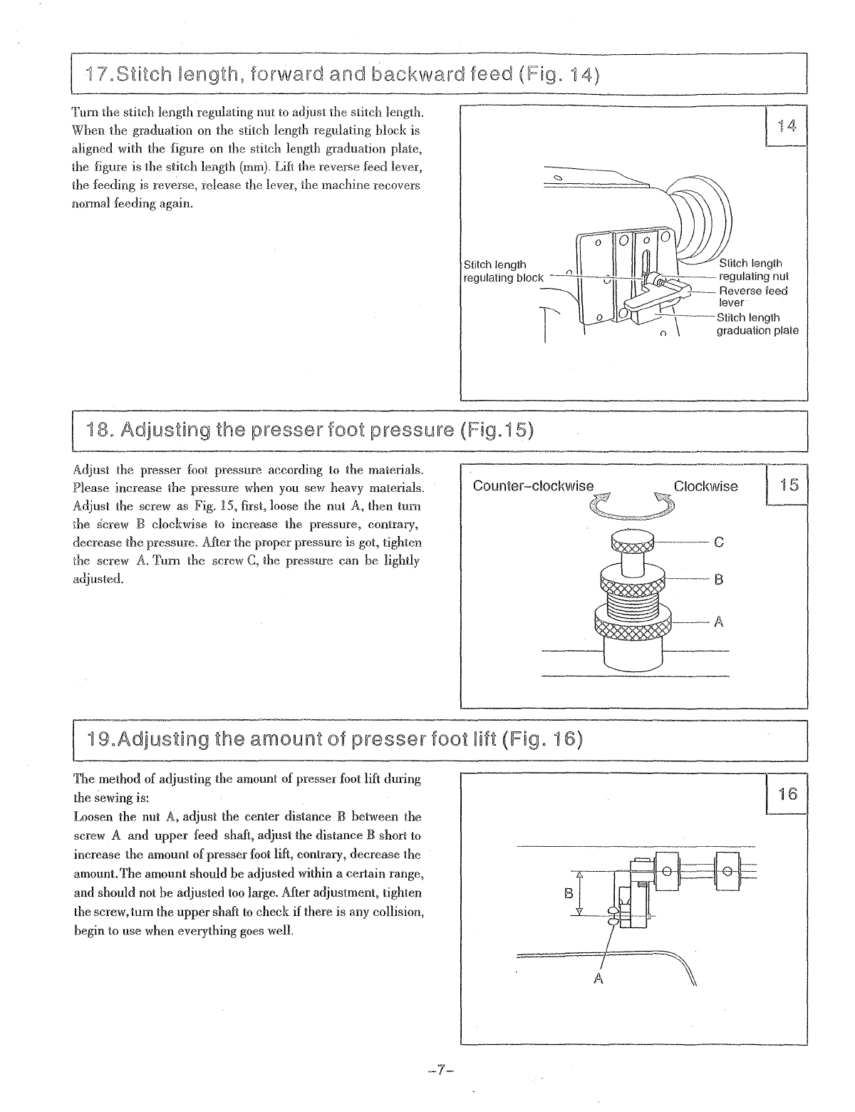
17.Stitch length, forward and backward feed..........................................................0
.................
7
is.Adjusting presser foot pressure........................................................,................................
..
19.Adjusting the amount of presser foot lift..........................................................................
..
20.Adjusting the timing of feed..................................................................................................8
21.Adjusting the timing between needle and hook....................................................................8
22.lnstalling the hook positioning bracket and
hoolc
................................................................8
i.Machine body....................................................................................................................
9~i0
2.Upper shaft and thread
take-up
mechanism..................................................................
11-12
3.Needle bar, rocking shaft, presser foot mechanism......
oo
................
oo
..............................
13-14-
4.Vertical shaft, lower shaft mechanism.............................................................................
15-16
5.Feed mechanism.............................................................................................................17-·18
6.Threading mechanism.....................................................................................................
19~20
7.Accessories ........................................0
...........................................................................
21
o E
10
I
STRUCTIO
1.
Brief
introducHon
This machine is designed with sliding lever
to
take up thread
and horizontal hook catch thread, which product lockstitch.
Upper and lower shafts are driven by bevel gears; lever type
stitch regulator, compound feed
by
feed dog, needle and
walking foot; high presser foot stroke and lifter, and long stitch
length, cylinder bed, Little running noise, it works well
what-
ever
the
surface of materials is smooth or roughness. It's easy
for sewing multi-layer leather and materials.
It's
Vlr:idely
used for binding sewing on the medium and heavy
weight materials. (such as: handbag, shoes and other cylinder
type materials binding
se\\r:ing)
Unison feed
by
binder, feed dog, presser feed and needle,
which assures fully binding.
I
3.
Machine
ins~a!!aHon
1.
Location of the machine
The machine must be located on
th~
rigid and flat floor for
ensuring. its smooth operation and reducing its vibration.
Meanwhile, a rubber mat should be inserted between the
machine stand and the floor for further reducing the running
nOIse.
2. Install the base and oil pan(Fig.
1)
First, Align the four screw holes of the machine base with
the ones
of
the table and plunge four bolts A and tighten
the nuts. Then put the oil pan on the machine base smoothly.
3. Install the machine head (Fig. 2)
First, half of the hinge should
be
made
to
engage with the
machine base, then put the machine head lightly on the
machine base, move it slightly to align the three screw
holes of the head with the ones of the hinge, insert three
screws A and tighten them.
2JViain
specifications
~lication
Medium
and
heavy
weight
materials
---
Max.sewing
speed
2500s.p.m
---
Stitch
leng~h
O~6mm
Needle
bar
stroke
33.2mm
----~
Presser
foot lift
8mm
by
hand
height
l3mm
by
pedal
._-
Hook
Horizontal hook
Needle
DPx
17
16"-18"
Lubrication
--
Oiied
by
hand
--
--
-~
Motor
power
370W
------------
--
Cylinder dia. 46mm
1
oil
pa.n
I
ta.ble
;f/
I
~
2
o o hinge
4.!nstadiing
~he
motor
(Fig.3) J
'-------~---~-
A
c~
B
Align machine balance wheel belt groove A with motor pulley
belt groove B by moving motor C leftward or rightward.
Be sure that the belt is not touched with the table.
5.Connectting bettween the pedal and the ciutch lever (lFigA)
F:-·
-==±=
E-,---I-l-
D---+-t'
C--~
B
___
-+r
A~~~
4
1.
The optimum tilt angle of pedal A against floor is approx.
15° .
2. Adjust the clutch of motor E so that the rod B and the
clutch lever C run in one line.
3. When running, the machine balance wheel G should rotate
counter-clockwise observed from opposite side of the
balance wheel. The motor D rotates in the same direction.
Thf
rotation of motor can change by reversing the plug of
the motor.
4. Adjust the tension of V
-belt
by moving motor upward
or downward, The projJer tension of V
-belt
is a slack of
1O-12mm when the V
-belt
is
depressed by forefinger.
6Jnsttamng the
presser
foot
mt
contro~
piatte (lFig.5)
---c
A
D
E
5 First, the chain
hook
A should be connected to the presser
foot lift lever
C,
then put the pedal assembly D on the stand,
move the control plate E leftward or rightward until the chain
becomes on one line, Tighten the bolts
and
nuts, finally,
connect the chain hook to the control plate.
7J
ns~ai~ing
the
bobbin
V\f~nder
(FiQ].
6)
Align pulley B of the bobbin
V<linder
with the outside of the
V-
belt
C,
and there should be a proper clearance between them;
so
that pulley B can be touched with the V
-belt
when latch
thumb lever A is depressed, thereby the V
-belt
can drive the
pulley Bwhile the machine running.The bobbin winder should
be parallel with belt slit E of the table, then fasten
two
wooden
screws
D.
The thread stand should be located
on
the right backside of
the table. Threading should be smooth when sewing.When the
machine head is turned backward, it should not be touched
with the thread stand, thentighten the nut
C.
1.
Clearing the machine
Before the head is packed, all of the parts of the machine are
coated with anti-rustgrease,meanwhile the grease can harden
and the dust can cover the machine surface during long time
storage and shipment, so, the dust and grease must be cleared
by clean cloth with gasoline.
2. Examination
Although every machine is conformed
by
strict inspection and
test before delivery, the parts of the machine may
be
loose and
deformed afterlong distance transportation with jolt.Athorough
examination must be performed. Turn the balance wheel
slightly by hand to check ifthere is running obstruction, parts
collision, uneven resistance and abnormal noise.
If
any of
these exist, adjustment must
be
made accordingly before
running.
-3-
C-----"'0~
8----\\\\\0
7
'"
"
Ii>
o 0
-~,:-
I ,
b
1
O.lubrication
(Fig,B) J
'------'---
Before running, the machine must be oiled at the places
by
arrow shown.
If
the machine continues in operation, it should
be oiled not less
two
times
per
shift. Please use HA
-8
sewing
machine
oil
or
TJ-70
machine
oiL
11
.Tria! running
Trial running is required when new machine is put into use or
use again after storing quite long time. Please lift the presser
foot
and run the machine at a low speed of
1000-1500
s.p.m
for
30
minutes, then increase the speed gradually.
9
@Jnstamn
g
the
needie
(Fig,9)
-4-
Tum
the balance wheel to lift the needle
bar
to
its highest
position, loosen the
needle
sei screw, and make the needle
groove to the left side of the operator, then fully insert the
needle shank until to the bottom of the needle
bar
socket,
tighten the set screw. (Fig 9a)
Note:lnsufficient insertion (Fig. 9b)or the needle groove facing
to
the operator (Fig. 9c) is incorrect.
13,
rdination
among
the ne Ie,
thread
and
maieria~s
The needle thread should be left-twist, holding the thread by
left hand, twist it by right hand at certain direction (shown as
Fig. 10),
if
ii changes .into tight, it's left-twist, contary, it's
right-twist.
Please
use
DP x
17
16"
~
18"
needle, The needle size should
depend on the materials to
be
sewn.
If
the thin needle is used
for sewing heavy materials, the needle will be broken easily,
and will also cause skip and thread broken. On the contrary,
the materials will be destroyed for the big needle hole, so,
please select proper needle
and
thread according
to
the
materials.
14.Threading the
need~e
thread (Fig.11)
Tum
the balance wheel to lift the thread
take-up
to
its highest
position, then threading the thread from the thread stand.
Threading order as Fig.11: upper cover thread guide
A-lihree
-hole
thread guide
B-lihread
tension disc C-l>spring guide
disc D-l>spring
E-lihread
guide (upper) F-l>thread
take-up
G
-lihread
guide (upper)
F---->cj:h.read
guide (middle) H-l>thread
guide
Qower)
K-l>needle
bar
thread guide J-l>needle
K.
When
drawing the bobbin thread, holding the tip ofthe needle
thread by hand,thru the balance wheel to lower the needle bar,
then lift
it
to
ias
highest position.
Pull
the needle thread and
the bobbin thread
'will
be
drav\Tfi
up
accordingly, finally, put
the tipe
of
the needle thread
and
bobbin thread toward front
under
the persserfoot.
15.Adjusting
the
tension
of
bobbin
thread
and
needle
thread
(Fig.
12)
The tension of needle thread
and
bobbin thread should be
suitable.
The
stitch form shown as
CD
is the best.
If
the tension
is tightened or loosened, the abnonnal stitch form will be
caused shown as
(2),
®
1.
Adjusting the tension of bobbin thread.
The
tension of bobbin thread should be adjusted according to
the materials:
CD
Turn the balance wheel by
hand
to lift the thread
take-
up to its highest position;
(2)
Take down the sliding plate, the screw A is shown as
Fig.
12
(1);
® Turn the screw A clockwise to increase the tension of
bobbin thread;
@
Tum
the screw A counter-clockwise
to
decrease the
tension of bobbin thread;
OeD
X®~~~~~~~
)<@~~~~~~~
11
12
(3)
(2)
Standard clearance Bmm
II/fl---f..--
A
,.,M'----I--
B
2. Adjusting the tension
of
needle thread
(1)
Adjusting the pressure on the thread tension disc:
Adjusting the pressure
on
the thread tension disc
to
change
the tension of needle thread.
As
Fig. (2), turn the nut A
clockwise
10
increase the pressure, on the contrary, to
decrease the pressure.
(2)
Adjusting the tension of spring
Light materials 20g
Normal materials 25g
Heavy materials 30g
The method ofadjustment as Fig.
(3):
Loosen the nut
A,
turn the spring shaft counter-clockwise to
increase the tension, contrary,
to
decrease the tension. Please
use a screwdriver
to
rotate the spring shaft
to
get the
required tension.
(3)
The swing range
of
the spring
The spring must be able
to
swing, when the thread
take-up
is at its highest position, the normal swing range ofthe thread
take-up
spring should be:
Light materials
Normal materials over 8mm
about8mm
Heavy materials less 8mm
The method ofadjusting swing range: as Fig (4)
(j)
Loosen the presser foot lifter;
(2)
Loosen the screw
A;
®
Tum
the disc B counter-clockwise to increase the
swing range, contrary, the swing range decrease.
(j;; Tighten the screw
A.
i
rELWinding
the
bobbin
thread and
adjustment
(Fig. 13)
13
A
D
E
The bobbin thread should be neat and tight.
If
the thread
is weak, please increase the tension of the thread tension
disc
A;
if
the thread is not neat, please move the bracket C
to
adjust it. First, loosen the screw B, if the thread is wound
to one side as Fig
(2),
move the bracket rightward;
if
it is as
Fig
®,
please move the bracket leftward until the thread is
wound neatly
as
Fig.
CD,
then lighten the screw.
Cote: Nylon or polyester thread should be wound under ligbt
tension in particular,otherwise the bobbin D might be broken
or deformed.Please don't overfill the bobbin thread,otherwise
the thread will loosen dovm from the bobbin. The optimum
capacity of bobbin thread is
fill
about
80%
of bobbin outside
diameter, and this can be adjusted by screw K
,
forward
and
backwa
Tum
the stitch length regulating
nut
to
adjust the stitch length.
When
the
graduation on the stitch length regulating block is
aligned with the figure
on
the stitch length graduation plate,
the figure is the stitch length
(mm).
Lift the reverse feed lever,
the feeding is reverse, release the lever, the machine recovers
normal feeding again.
ed (Fig" 14)
14
ro 0 0
Stitch length
Cl
Stitch length
regulating block
--~ifWw<:::t:::---
regulating nut
f o
--
Reverse ieed
lever
-,---';----Stitch
length
graduation plate
18"
Adjusting
the
presser
froot
pressure
(Fig"15)
Adjust the presser foot pressure according to the materials.
Please increase
the
pressure when you sew heavy materials.
Adjust
the
screw as Fig. 15, first, loose the nut A, then
tum
the
SCl'ew
B clockwise to increase the pressure, contrary,
decrease
the
pressure. After the proper pressure is got, tighten
the screw
A.
Turn
the screw
C,
the pressure can be lightly
adjusted.
Counter-clockwise Clockwise
P.·".'.
'.
..
~,
..
,
~
19"Adjusting
the
amount
of
presser
foot iiH (Fig. 1S)
The method of adjusting the amount of presser foot Mt during
the sewing is:
Loosen the nut A, adjust the center distance B between the
screw A and
upper
feed shaft, adjust the distance B short to
increase
the
amount
of
presserfoot lift, contrary,
decrease
the
amount.The amount should be adjusted within a certain range,
and should not be adjusted too large. After adjustment, tighten
the screw,turn the
upper
shaft
to
check if there
is
any collision,
begin to use when everything goes well.
-7-
B
/
A
15
16
10--I+-J'I---
A
i.2mm
O.05mm
17
I 20.Adjllsting the timing of feed
1.
Standard position
The needle should align with the needle hole center on the
feed dog, please adjust the upper feed shaft cam
to
adjust the
timing of feed.
2. Installing the feed cam
First,adjust the stitch length
to
zero, and open the upper cover,
tum the balance wheel counter-clockwise by right hand, the
second screw on the feed cam should align with the groove on
the upper shaft.
21.Adjllsting the timing between the
needle and hook(Fig. 17)
The position between hook and needle should be set as
following order. Lift the needle up
to
1.9mm from its lowest
position,the tip of hook should be straight
to
the needle center
line, and there is about 2.1mm distance between the tip of
hook and upside of needle hole.
If
the position is wrong,please
loosen the screw
A,
move the needle bar up and down until it
is
on proper position, then tighten the screw. When adjustmet,
also please notice the lateral clearance between the tip ofhook
and needle,the proper clearance between the bottom ofneedle
gap and the tip of hook is
O-O.Smm.
22Jnstalling the hook positioning
bracket and hook (Fig.iS)
1.
Installing the hook positioning bracket
When installing the hook positioning bracket A, the flange of
the bracket should enter into the hollowness of hook inner
head
S,
and there is a clearance of O.S-O.7mm.
2.
Installing the hook
Lift
the presser foot and the needle bar
to
its hightest position,
open the bed cover,unscrew the four screws of hook positioning
bracket, then
tum
the balance wheel and loosen the
two
sei
screws
D,
finally, pull the hook out slowly, together with the
positioning bracket. Install the hook in the reverse order thai
the hook is taken down.
P·
T;
..
•·
~
44~.
~
43
2
33-l~1
34-J:
.
35
@3
-9-
1
,Machine
body
Ref.
NO.
Parts
No.
Name of parts Qty. Remarks
1
49WF2-004
Face plate 1
2
49WF2-005
Screw for face plate 1
3
49WF2-006
Pin for face plate 1
4
37T4-422
Back cover 1
5
13
WF2-0
10 Screw for back cover 2
6
49WF2-023
Cylinder 1
7
16WF2-038
Oil stopper plate 1
8
16WFI-059
Screw 1 SM9/64" X
40
9
49WF2-011
Upper plate 1
10
49WF2-013
Upper sheet plate packing 1
11
49WF2-008
Thread
take-up
cover 1
12
49WF2-009
Screw 1 SMl1l64" x
40
13
49WF2-020
Pin 1
14
49WF2-019
Lubrication dial 1
15
17T5-016
Set screw 1 SM15/64" x
28
16
49WF2-018
Spring 1
17
49WF2-017
Lubrication dial stud 1
18
49WF2-014
Oil gauge window 1
19
49WF2-012
Screw 7 SM9/64"
x40
20
49WF2-0l5
Spring plate 1
21
49WF2-012
Screw 1
22
7KTI-020
Washer 1
23
16WF3-014
Screw 1 SM1/8" x
40
24
49WF2-016
Oil adjusting collar 1
25
49WF2-003
Base 1
26 49WF2-'OlO Oil pan 1
27
22WF2-006
Screw assembly 1
28
37T4-411
Spring washer 1
29
37T4-409
Connecting hook 1
30
22WF2-020
Screw 1 SM1I4" x 28
31
37T4-407
Hinge 1
32
22WF2-004
Screw 6
M6xl
33 Screw 4
M8
x 75
GB68-85
34 Washer 4
GB96-85-8
35 Nut 4
GB41-86-8M
36
49WF2-021
Oil pipe 1
37 Oil wick 1
38
16WF2-053
Logo label 1
39 Rivet 4 GB827
-86
2.5 X 5
40
lKTl-005
Warning label 1
41
49WF2-034
Model label 1
42
4KTI-005
Series number label 1
43
35WFI-054
Rivet 2
44
49WF2-036
Safety cover 1
45
13WFI-045
Screw 2
,
.
---
~-
-
-~-
----~~~
2 3 1 4
l
s-LPf
6
20~
18
19
~~
~.~
.~
..
~
~
I
,
I
!
I
16
17
7 o
8
.......
~
~
@
1,1
I 1
9
10
11
12
24
-11-
27
28
~
, I
hS
I I
I
I
I
I I
,-,
I I
I I
I I
I I
I I
I I
. I I
W
37
38
I
I
32
34
\
35
36
,,~
Ref.
NO.
Paris
No.
Name of parts Qty. Remarks
1
49WFl-005
Thread take-up 1
2
49WFI-003
Thread take-up pin 1
3
49WFI-004
Screw 1 SM17/64"
)(
32
4
Oil
wick 1
5 16WFI-013 Thread take-up slide block 1
6
Oil
1
7
16WFI-014
Needle crank rod 1
8
49WFI-006
Rubhercap 1
9
Oil
wick 1
10 16WFI-015 Needle bar crank pin 1
11
16WFl-016
Set screw 1 SM1I4")( 28
12 16WFI-017 Screw 1 SM1I4")( 28
13
16WFl-019
Ser screw 1 SM1I4")( 28
14
16WFI-018 Needle crank 1
15
16WFI-020
Screw 1 SM1I4")( 28
16
22WF2-049 Screw 1 SM5/16" x 28
17
Oil wick 1
18
16WFI-021 Washer 1
19
22WFI-053 Upper shaft bush
(L)
1
20
I 16WFI-025 Felt 2
21
49WFI-007
Upper shaft 1
22 49WFl-(108 Upper shaft bush
(M)
1
23
16WFI-004
Screw 1 SM17/64" x 32
24 16WFI-025 Felt 1
25
49WFI-012
Upper shaft collar 1
26 22WFl,..048 Screw 2 SM1I4" x 28
27
49WFI-013
Upper shaft bevel gear 1
28
49WFI-014
Screw 1
SM1I4"
x40
29
49WFl-015
Set screw 1 SM1I4"
x40
30
49WFI-009
Upper shaft bush 1
31
16WFI-004
Screw 1 SM17/64" x 32
32 49WFI-OlO Felt 1
33 49WFI-Ol1 Small felt 1
34 16WFI-056 Screw 1 SM1I4" x 32
35 22WFI-008 Ring 1
36
13WFI-On
Set screw 1 SM15/64" x 28
37 13WFI-078 Screw 1 SM15/64" x 28
38 16WFI-035 Pulley 1
39
16WFI-040
Screw 1
SMl1/32"
x 28
40 49WFI-017 Screw 1 SM9/64" x
40
41
49WFI-016
Gear cover
(U)
1
_J
-12-
--"
W
I
81
74<:;
~J
I
73
~I
.~.~.
I
/------::::-1
L46 .
II
1 I U .
77
1
§l
I
g--50
I
I
15
57
·0---,-59
~~
t~-66
68
~9
65U
64-\
I
28~
27
U,
w
Z
lro
13
J-12
I
~
I~
if
ilro
©P
i
5
14
0
()
~
I
o
,n
f.
Ii
(\)
U
II=;;
OF""
8.
'"
I
3B
iO
10
9
~.~
~1
2 I;:
1.
1
-----~--~
7 <:>
~
.
~
I
0.
0 .
()
42
<l®--43
~45
82
I
3
=if;,
o
o
r;=!?
13
I:
~
I
'
~
.
=!o
I:
3
I:
i
i
ii
t
r foot mechanism
Ref.
NO.
Parts
No.
Name
Of
parts Qt)'. Remarks
ReLNO.
Parts
No.
Name
of
parts Qty. Remarks
1 49WFS-006
Inner
presser
foot
vertical
cam
1
43
22WFI-003
Screw
1 SMTl/64" x 32
2 22\)\'F4-002
Set
screw
2
SM1I4"
x 40
44
49WFI-002
Needle
bar
thread
guide
1
3
Needle
bearing
1
45
Needle
1
DPx
17
16#
4
22W.FS-021
Eccentric
wheel
connecting
rod
1 46 49WF3-004
Pressure
adjustment
screw(small)
1
5 22WFS-025
Screw
2 SM7/32" x 32
47
49WF3-001
Pressure
adjustment
screw(big)
1
6 22WFS-024
Collar
1
48
49WF3-002
Screw
1
7 22WFS-020
Nut
1 49 49WF3-006
Spring
pin
1
8 22w.FS-0l9
Collar
1
SO
49WF3-00S
Spring
1
9 16WF2-023
Washer
1
51
22WF3-00S
Presser
bar
1
10 22WFS-0l8
Stud
screw
1
S2
49w.F3-003
Spring
1
11
22WFS-017
Crank
1
53
22WF3-007
Presser
bar
lifter
1
12 16WF3-030
Clamping
screw
1
SM1I4"
x
28
54 16WF2-033
Screw
1 SMll/64" x 40
13
22WFS-013
Upper
feed
shaft
hush
1
5S
49WF3-009
Roller
screw
1
14 22w.FS-012
Upper
feed
shaft
1
56
49WF3-OlO
Roller
1
IS 22w.F5-013
Upper
feed
shaft
bush
1 57 22WF3-009
Thread
release
plate
1
16 22WF5-016
Nut
1
58
22WF3-008
Thread
release
spring
1
17 22WF5-015
Pin
screw
1 59 16w.F4-021
Presser
bar
guide
1
18
Oil
wick
1 60 16w.F4-022
Screw
1 SM9/64"
x40
19
22WFS-014
Link
1
61
16w.F3-025
Setscrew
1 SM17I64" x
32
,
20 22WF5-026
Swing
plate
1 62 49w.F3-007
Presser
bar
bush
1
I
21
49WFS-009
Pressure
adjustment
screw
1 SM5/16" x 24
63
22w.F3-014
Set
screw
1 SM9/64"
x40
22 22w.FS-031
Spring
rod
1 64 49WF3-015
Outer
presser
foot
1
23
49WFS-007
Spring
1
65
6K2-042
Screw
1
M6x
1
24 22WF5-028
Link
1 66
49VtTF3--D08
Presser
bar
guide
shaft
1
2S
22WF5-009
Slide
block
1 67 22WF3-011
Screw
1
SM1I4"
x28
26 22WF5-029
Inner
presser
foot
bar
1 68 22w.F3-01O
Presser
plate
1
27 49WFS-008
Imler
presser
foot
1 69 22WF3-012
Pin
1
28 22w.FS-033
Screw
1 SM5/32"
x40
70
16W4F-OOl
Pin
screw
1
29 16WFI-Oll
Screw
1 SM17/64" x 32
71
16W4F-002
Presser
foot
lifter
1
30
22w.FS-002
Rocking
frame
shaft
1 72 49w.F3-011
Thread
release
guiding
plate
1
31
Oil
wick
1
73
49WF3-012
Screw
2 SMlS/64" x 28
32
22WFS--D03
Bridging
plate
1 74 49WF3-014
Screw
2 M5xO.8
33 16WFI-059
Screw
2 SM9/64"
x40
7S
49WF3-013
Stopper
block
1
34 6K2-019
Screw
2 M4xO.7 76 22w.F3-002
Presser
fool
lifter
lever
1
3S
22T1-007
Washer
2 77 22WF3-001
Presser
spring
1
36 49WF5-001
Guide
plate
1 78 16WF3-0S9
Screw
1 SMl/4" x
28
37 22WF5-001
Nee(lle
bar
rocking
frame
1 79 22w.F3-004
Nut
2
38
Oil
wick
1 80 22WF3-003
Set
screw
1 SM15/64" x
28
39
Oil
wick
1
81
22w.F3-015
Stopper
1
40
22WFI-004
Connecting
stud
1 82 49w.F5-010
Oil
wick
set
ring
1
41
16WFI-009
Screw
1 M4xO.7
83
49\)\'F2-012
Setscrew
1
42 49w.FI-OOl
Needle
bar
~~~~-=-~
~.'
~~~
.~~~-=-====-~~-.
~===~.
~-~~'='
~
~14-
3--
6---1
7
14
~
.
---------
----------1
---------
.
I
~
---------
---------
---I I
,_________
')
L-
----------
: -
. - - I
_________
~
I
_--
:
-----r--
21
v--
20
~
22
,-
-
Ref.
NO.
Parts
No.
Name of parts Qty. Remarks
1
49WFI-019
Vertic.al shaft gear
(U)
1
2
49WFI-020
Set screw 2 SM1I4" x
40
3
49WFI-023
Vertical shaft bush
(U)
1
4 16WF3-025 Set screw 1 SM17/64" x 32
5
49WF1-025
Felt 2
6
49WFI-018
Vertical shaft 1
7
49WFI-024
Vertical shaft bush
(L)
1
8
16WFI-004
Set screw 1 SM17/64" x 32
9
49WFI-021
Vertical shaft gear
(L)
1
10
49WFI-020
Set screw 2
S1\1114"
x
40
11
49WFl-027
Lower shaft gear 1
12
49WFI-015
Set screw 2 SM1I4" x
40
13
49WFl-030
Lower shaft bush
(B)
1
14
49WFI-031
Felt 1
15
16WFI-004
Screw 1 SM17/64" x
32
16
49WFl-032
Lower shaft collar 1
17
7K13-026
Screw 2 SlVHl/64" x
32
18
49WFI-026
Lower shaft 1
19
49WFI-029
Lower shaft bush (A) 1
20
Bobbin case 1 SC39-14
21
49WFI-033
Bobbin 1
22
Rotary hook 1 KR69-V
~~~
~~~~~
--~~--~~-~~~~~~~-~~
~
-~
--
-
~
-16-

Other manuals for 277RFS-3

1

Other Consew Sewing Machine manuals

Consew 277RFS-3 Datasheet

Consew

Consew 277RFS-3 Datasheet

Consew 18 Use and care manual

Consew

Consew 18 Use and care manual

Consew 146RB-1A-1 User manual

Consew

Consew 146RB-1A-1 User manual

Consew 199R-1A User manual

Consew

Consew 199R-1A User manual

Consew 133A-1 User manual

Consew

Consew 133A-1 User manual

Consew 104-10T User manual

Consew

Consew 104-10T User manual

Consew 1118-3 Operation manual

Consew

Consew 1118-3 Operation manual

Consew 222 User manual

Consew

Consew 222 User manual

Consew 345-3 User manual

Consew

Consew 345-3 User manual

Consew P1541S-CC Technical manual

Consew

Consew P1541S-CC Technical manual

Consew 3421UX5-2 User manual

Consew

Consew 3421UX5-2 User manual

Consew 7360R Parts list manual

Consew

Consew 7360R Parts list manual

Consew 227r-2 Guide

Consew

Consew 227r-2 Guide

Consew 733R-5 Use and care manual

Consew

Consew 733R-5 Use and care manual

Consew 30 Use and care manual

Consew

Consew 30 Use and care manual

Consew 333RB-3 User manual

Consew

Consew 333RB-3 User manual

Consew P1206RB Technical manual

Consew

Consew P1206RB Technical manual

Consew 210 Instruction Manual

Consew

Consew 210 Instruction Manual

Consew 222 User manual

Consew

Consew 222 User manual

Consew Sewing Machine User manual

Consew

Consew Sewing Machine User manual

Consew 744R10-1 User manual

Consew

Consew 744R10-1 User manual

Consew SK 2R Manual

Consew

Consew SK 2R Manual

Consew 30 Use and care manual

Consew

Consew 30 Use and care manual

Consew 227r-2 Guide

Consew

Consew 227r-2 Guide

Popular Sewing Machine manuals by other brands

Duerkopp Adler 670 Service instructions

Duerkopp Adler

Duerkopp Adler 670 Service instructions

Riccar 925 Instruction book

Riccar

Riccar 925 Instruction book

ELNA 845 - Supplementary instructions

ELNA

ELNA 845 - Supplementary instructions

ZOJE ZJ1900DSS manual

ZOJE

ZOJE ZJ1900DSS manual

Brother KX395 user manual

Brother

Brother KX395 user manual

Husqvarna 555 user guide

Husqvarna

Husqvarna 555 user guide

Singer 6180 Operation and safety notes

Singer

Singer 6180 Operation and safety notes

ZOJE 20X manual

ZOJE

ZOJE 20X manual

Bernina classic 1008 brochure

Bernina

Bernina classic 1008 brochure

Axis 1114-1 Assembly and usage guide

Axis

Axis 1114-1 Assembly and usage guide

JUKI DDL-9000 instruction manual

JUKI

JUKI DDL-9000 instruction manual

ELNA eXcellence 780 Service manual

ELNA

ELNA eXcellence 780 Service manual

Janome 204D brochure

Janome

Janome 204D brochure

UnionSpecial 81300A INSTRUCTIONS AND ILLUSTRATED PARTS MANUAL

UnionSpecial

UnionSpecial 81300A INSTRUCTIONS AND ILLUSTRATED PARTS MANUAL

Singer 5-2 manual

Singer

Singer 5-2 manual

Singer 221K instructions

Singer

Singer 221K instructions

Singer 14SH644 Operator's guide

Singer

Singer 14SH644 Operator's guide

Husqvarna Viking Eden Rose 250C user guide

Husqvarna Viking

Husqvarna Viking Eden Rose 250C user guide

manuals.online logo
manuals.online logoBrands
  • About & Mission
  • Contact us
  • Privacy Policy
  • Terms and Conditions

Copyright 2025 Manuals.Online. All Rights Reserved.