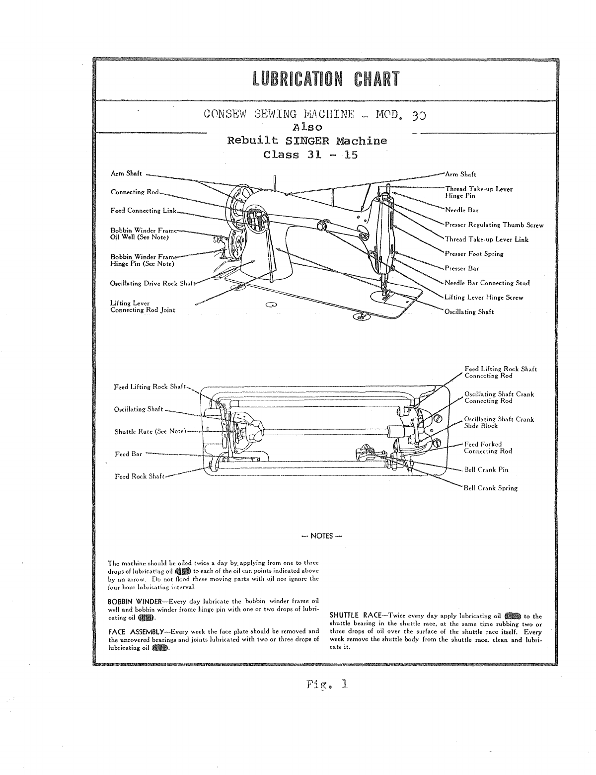
Consew 30 Use and care manual

0
RATING
INSTRUCTIONS,
PARTS
and
MAINTENANC
ROC
DUR
FOR
CONSEW
MOD
L
30
SEWING
MACHINE
CONSOLIDATED
SEWING
MACHINE
New
York
{California
From the library of: Superior Sewing Machine & Supply LLC

- 1 -
SETTING
~p
THE
V~CHINE
.
Carefully
unpack
machine
from
packing
case
and
make
sure
that
all
small
parts
and
accessories
are
removed
from
packing
material.
Wipe
machine
clean
of
protective
grease
and
lubricate
oil
holes
with
a
good
grade
of
sewing
machine
oil.
(see
Bel
miT)
CAPACITY
AND
SPE~Q
Maximum
operatinr:;
speed
after
a
break-in
period
is
2000-2200
stitches
per
minute
depending,
of
course,
on
the
type
of
material
being
sewn,
its
thickness
and
that
of
the
seams
being
crossed.
To
assure
durability
and
trouble-free
operation
it
is
imperative
that
for
the
first
several
weeks
of
operation
the
maximum
speed
is
held
t,o
not
more
than
2000
RPM
in
order
to
allow
the
parts
to
be-
come
nroperly
broken
in.
DIR~CTIO!Il
OF
ROTATION
_
_...
______,
__
-=----'~
In
operation
the
handwheel
of
the
machine
alwavs
turns
toward
the
operator.
To
avoid
tangled
threads
and
jamming
of
the
sewing
hook,
do
not
turn
hand
wheel
other~·Iise.
OILING
.,_,....,..,.,
__
__
Do
not
operate
the
machine,
even
if
only
for
testing,
unless
it
has
been
prouerly
oiled
at
every
spot
requiring
lubrication.
The
fol-
lowing
illustrations
indicate
these
spots.
Oiling
must
be done
at
least
twice
daily
1.vhen
the
machine
is
in
con-
tinuous
operation
to
assure
free
runninf,
and
durability
of
the
operating
parts.
NOTE---During
the
break-in
period
a new
machine
should
be
oiled
more
frequently.
LUBRICATION
CHART
....
_____
.._........___
..,
,
__
...,..._. '
The
lubrication
chart
(see
fig.
1)
nrescribes
lubrication
mainte-
nance.
The
service
interval
specified
on t.he
lubrication
chart
is
for
normal
operating
conditions.
Failure
will
result
in
malfunction-
ing
or
damage
to
the
machine.
The
lubricant
prescribed
for
use
on
the
machine
is
an
all-temperature
lubricante
fOINTS
OF
APP~IC~~TION
Lubrication
points
are
readily
located
by
reference
to
the
lubrica-
tion
chart,
which
is
supplemented
with
individual
photographs
of
the
points
of
lubrication
(see
figs
..
2
to
5).
Wipe
lubricators
and
surrounding
surfaces
clean
before
applying
lubricant.
From the library of: Superior Sewing Machine & Supply LLC

LUBRICATION
CHART
MOD
•
CONSEW
SEWING
MACHINE
.Also
Rebuilt
SINGER
Class
31
Machine
15
Arm
Shaft
Bobbin Winder Frame
Oil Well (See Note)
Bobbin Winder
Frame--
Hinge Pin (See Note)
Oscillating Drive Rock Shaft
Lifting Lever
Connecting Rod
Joint
-·NOTES-
The
machine should be oiled twice a day
by_
applying from one to three
drops
of
lubricating oil OJIto each
of
the oil can points indicated
above
by
an
arrow.
Do
not
flood
these
moving
parts
with ojl nor
ignore
the
four hour lubricating interval.
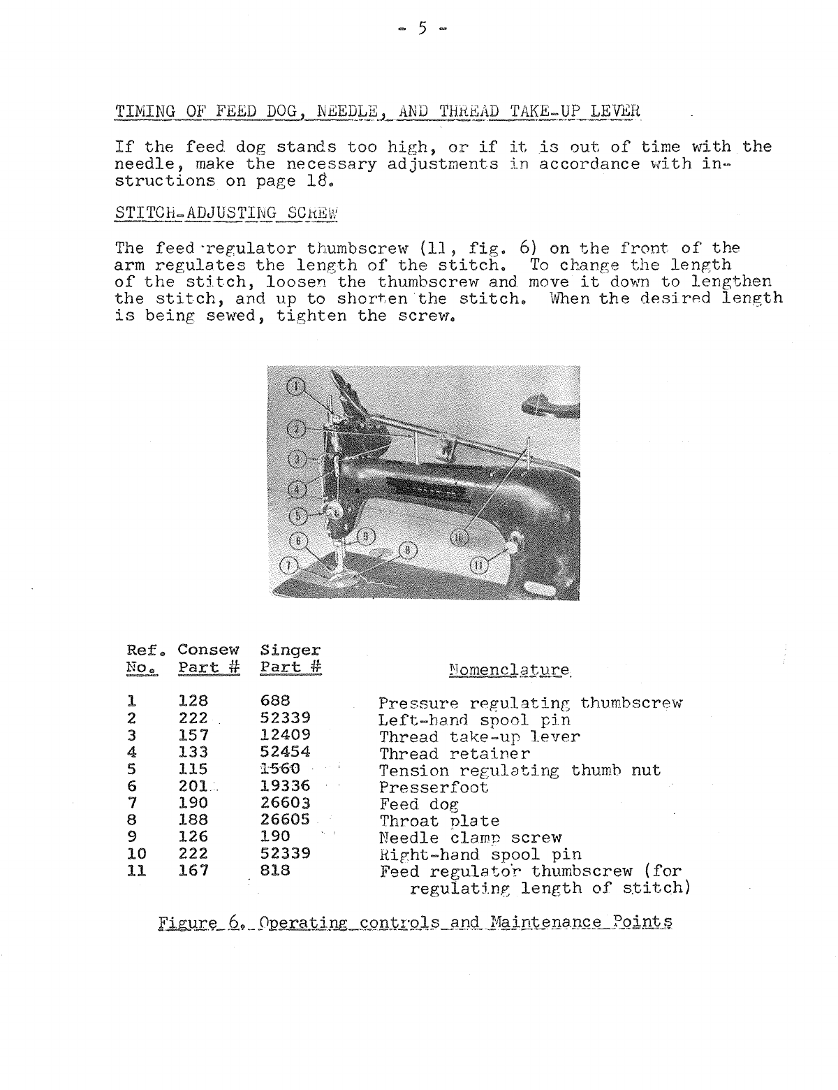
Needle Bar
Presser Regulating
Thumb
Screw
Thread
Take-up Lever Link
Presser
Foot
Spring
Presser Bar
Needle Bar Connecting
Stud
Lifting Lever Hinge Screw
Oscillating
Shaft
Feed Lifting Rock
Shaft
Connecting
Rod
Oscillating Shaft Crank
Connecting Rod
Oscillating Shaft
Crank
Slide Block
Feed Forked
Connecting
Rod
. Bell Crank Pin
Bell
Crank
Spring
BOBBIN
WINDER-Every
day lubricate the bobbin winder frame oil
well and bobbin winder frame hinge pin with one or two drops of
lubri~
eating oil
!Jill).
FACE ASSEMBLY-Every week the face plate should
be
removed and
the
uncovered bearings and
joints
lubricated
with
two
or three drops
of
lubricating oil fl'llilll).
SHUTTLE
RACE-Twice
every
day
apply lubricating oil fllllilll) to the
shuttle
bearing in the
shuttle
race,
at
the
same
time
rubbing
two
or
three drops
of
oil
over
the
surface
of
the
shuttle
race itself.
Every
week remove the sh\lttle body from the
shuttle
race. clean
and
lubri·
cate
it.
FiR:. J
From the library of: Superior Sewing Machine & Supply LLC

k~~rjcaQt.
The
lubricating
oil
used
to
lubricate
tbe
tailoring
machine
is
a
highly
refined
mineral
oil
with
a
low
nour
pointe
Ti:.
mav
be
used
in
all
temperatu:r·eso
~UB~J.:.9JlTI9J'J
..
.NOTES
gr~
JNPI..Y::tJLUJi.L
UNITS
AND
PARTS
(a)
Ttvice
daily,
add
one
to
three
drops
of
lubricatinp;
oil
to
the
followin~
parts:
1
..
Needle
bar.
2.
Needle
bar
connecting
stud.
3o
Presser
bar.
4.
Preseerfoot
spring.
5.
Presser
regulating
thumbscrew.
6.
Thread
take-up
lever
hinge
pin.
7.
Thread
take-up
lever
link.
(b)
Every
week, remove
the
faceplate,
clean
the
assembly,
and
lubricate
the
follo~rin.e:
moving
parts
with
two
or
three
drons
of
lub:ricatinp:
oil
to
supplement
the
surface
oiling
of
the
machine
(fig.
3}.
1
..
Needle
bar
connecting
stud
roller.
2.
Thread
take-up
crank.
)
..
Thread
take-up
lever
crank.
4.
Thread
take-up
lever
hinge
pin.
5
..
Thread
take-up
lever
link
hinge
pin.
Arm
assei11J2lY.o
T>trice
a
day,
add one
to
three
dJ~ons
of
lubricating
oil
to
the
following
moving
parts:
(a)
Arm
shaft
(to
be
lubricated
through
four
oilholes).
(b)
Feed
connecting
link.
(Loosen
the
thumbscrew
in
the
round
cover
plate
on
the
back
of
the
upr:i.ght
and
turn
the
cover
plate
up
to
lubricate
linko
{see
fig.
2).
(c)
Feed
lifting
rock
shaft
crank
connecting
rod., (See
note
in
(b)
above.}·
(d)
Lifting
lever
connecting
rod
.jointo
(e)
Lift.i
ng
lever
hinge
screw.
(f)
Oscillating
rock
shaft.
(~)
Oscillating
shafto
l3i!£LJ?)2.~?J1lhlY.
Twice a
day,
lubricate
the
following
movinp;
parts
with
one
to
three
drops
of
lubricating
oil
(
):
(a)
Bell
crank
pine
(b)
Bell
crank
springe
(c)
Feed
bar.
{d) Feed
drive
connecting
rod.
(e)
Feed
lifting
connecting:
rod.,
(f)
Feed
lifting
rock
shaft.
(g) Feed
rock
shafte
(h)
Oscillating
shafte
(i)
Oscillating
shaft
crank
connecting
rode
(.j)
Oscillating
shaft
crank
slj
de
block.
From the library of: Superior Sewing Machine & Supply LLC

- 5 =
If
the
feed
dog
stands
too
high,
or
if
it
is
out
of
time
with
the
needle,
make
the
necessary
adjustments
in
accordance
with
in-
structions
on
page
18.
STITCH-ADJUSTING
SCrtEW
-------'~
The
feed
-regulator
thumbscrew
(11,
fig.
6)
on
the
front
of
the
arm
regulates
the
length
of
the
stitch.
To
change
the
length
of
the
stitch,
loosen
the
thumbscrev-r and move
it
do1rm
to
lengthen
the
stitch,
and
up
to
short,en
the
stitch.
Wben
the
desi
rPd
length
is
being
sewed,
tighten
the
screv-r.
Ref.
Consew
Singer
No.
Part
#
Part
#
1
2
3
4
5
6
7
8
9
10
11
128
222
157
133
115
201.
190
188
126
222
167
688
52339
12409
52454
156'0
19336
26603
26605
190
52339
818
~Tomencl.SJtllr.e.
Pressure
rPgulatinc
thumbscrew
Left-hand
spool
pin
Thread
take-up
lever
Thread
retainer
Tension
regulating
thumb
nut
Presserfoot
Feed dog
Throat
nlate
Needle
6lamn
screw
Rir,ht-hand
spool
pin
Feed
regulato'r
thumbscrew
(for
regulatin~
length
of
s.titch)
From the library of: Superior Sewing Machine & Supply LLC

Refo
Nq.!
1
2
3
'
Part
No
•.~
0 0 & 0
15278
50lF
2996
62740
15140
2973
2974
- 7 -
Shuttle
bobbin
case
position
finger
Shuttle
tension
spring
Shuttle
tension
regulating
screw
Shuttle
bobbin
Shuttle
bobbifi
case,
complete
Shuttle
bobbin
case
latch
Shuttle
bobbin
case
latch
lever
Shuttle
bobbin
case
latch
lever
fulcrum
E,.i.gg~r~-
~ll.-
~
Shvt~lf?.~
bo
bbl!LQP-.§~_:vt.i.tb~.-s.~
rf.!:l!!_d~J
v:e~-·
.tndi
ca
tjN:;._.shvJ'-tlS1.
tepJ?_j._qp_
_r_egnJ-fl!,}_n_p:..
.§Ql:e_r!o
REMOVING
BOBBIN
-~'~>-""""""""------·"''-·--
a., Turn
the
balance
~rhe0l
toward
y0P
unt:i.l
the
needle
moves
ur
to
its
highest
point
..
b.,
Draw
out
the
slide
(view
plate)
in
the
bed
of
the
machine.
c.,
Heach
under
the
stand
tope
W:i.tt
the
thumb and forefin(<'l'er
of
the
left
hand.,
open
the
latch
on
the
bobbin
case
(see
fig
..
lj)
and,
holding
the
bobbin
case
by
the
latch,
lift
it
to
the
left
and
out
of
the
shuttle
race.
d
..
As
long
as
the
latch
is
held
open,
a
sliding
lug
inside
the
bobbin
case
'holds
the
bobbin
ineide
the
case..
When
the
bobbin
case
is
turned
open-sidP.
do'm,
and
the
latch
is
released,.
the
bobbin
will
drop
out,.
Do
not
tr:r
to
force
the
bobbin
out
of
the
case
while
the
latch
is
open,.
.!f~Nj)JNG
,EO®JN
To
wind
thread
on
bobbin,
prcc.eed
as
follows:
a.
Place
the
bobbin
on
the
bobbin
winder
spindle
and
push
it
on
as
far
as
it
\'fill
go,
as
illustrated
in
figure
9.,
b,.
Pass
the
thread
from
the
bobbin
thread
cone
~'m
the
thre.qd
stand
dovm
throue:h
the
thread
hole
in
the
tension
bracket
C9
~
fig.9)
and
down
between
the
bobbin
winder
tension
disks
(1,
fige9J
c
..
Pull
the
thread
from
the
loV<;er
side
of
the
tension
disks
to
the
bobbin
(12,
f'ig
..
9)
•
From the library of: Superior Sewing Machine & Supply LLC

- 9 -
a.,
Figure
10
shovrs
the
relative
positions
of
the
bobbin
case,
bobbin,
and
thread
when
the
bobbin
is
put
into
the
bobbin
case.,
The
thread
should
draw
over
the
top
of
the
bobbin
and
from
left
to
right
just
before
the
babbin
is
slinped
into
the
case.,
b.,
To
thread
the
bobbin
case,
hold
it
in
the
left
hand,
as
shov-m
in
A,
figure
11,
the
slot
in
the
edge
being
near
the
top,
and
place
the
bobbin
in
the
case
so
that
the
thread
nulls
over
the
top
of
the
bobbin
and
away
from
you.,
c.
Pull
the
thread
into
the
bobbin
case
thread
slot,
as
in
B,
figure
11,
draw
the
thread
down
under
the
bobbin
case
tension
spring
and
into
the
delivery
eye
at
the
end
of
the
tension
sprine,
as
in
C,
figure
11.
c
From the library of: Superior Sewing Machine & Supply LLC

-
11
-
Remember--uneven,
knotted
or
rough
thread
imnairs
the
satisfactory
sewing
performance
of
your
machine.
Only
left.
twist
thread
is
to
be
used
for
the
needle.,
To
test
for
tNist
hold
a
length
of
thread
between
thumbs
and
index
fingers
of
your
hands.
Turn
thread
counterclockwise.
If
it
will
tlvist
tighter,
it
has
a
left
twist.
If
it
unravels,
it
has
a
right
twist.
The
bobbin
c2n
be wound
with
either
left
or
right
t1.vist
thread.
NEEDLE
AND
THfi.EAD
CHART
Needle
Size
SETTING
NEEDLE
·----#--
11
14
16
1e
20
22
Thread
Size
(Cotton)
80-100
60-70
40-60
30-40
24-30
16-24
a.
Select
a good
needle
of
the
proper
size
as
explained
abovee
Never
use
a
bent
needle
or
one
vri
th
the
point
blunted
or
turned.
Set
the
needle
\vith
the
long
groove
to
the
left.
b.
To
set
the
needle,
turn
the
balance
wheel
toward
you
until
the
needle
bar
moves up
to
its
highest
uoint.
c.
Loosen
the
needle
clamp
screw
(9,
fig.
6),
put
tbe
shank
of
the
needle
up
into
the
clamp
as
far
as
it
will
go,
and
turn
the
long
groove
of
the
needle
so
thRt
it
faces
to
the
left
and
is
di-
rectly
in
line
with
the
arm
of
the
l1k1.chine.
d.,
Tighten
the
needle
clamp
scr·e'."~•
If
the
screw
is
too
loose,
the
needle
will
turn
or
slir.
Figure
13.,
Bobbin
case
in
shuttls
race,
with
bobbin
thread
ready
to
be
nicked
uu
by
~0edlP
tl~ead.
From the library of: Superior Sewing Machine & Supply LLC

~
13
-
ao
After
the
needle
has
been
threaded
and
the
bobbir.
case
renlaced,
the
operator
must
use
the
needle
thread
to
catch
and
draw
the
bobbin
thread
up
through
the
hole
in
the
throat
plate,
as
illustrated
in
fig.l5.
bo
By
operating
the
hand
lifting
lever,
lock
the
:Dresserfoot
in
its
raised
position.
c.
With
the
left
hand;
hold
the
end
of
the
needle
thread
a
little
slack.
d.
With
the
right
hand,
turn
the
balance
wheel
down
toward
you
untiJ
the
needle
moves from
its
highest
position
down
and
back
up
to
its
high-
est
position.
If
the
needle
thread
is
held
with
a
lir;ht
tension
during
this
operation,
and
if
the
needle
is
correctly
timed,
it
vnll
catch
the
bobbin
threado
e
..
Draw up
the
needle
thread,
and
the
b0bbin
thread
w;
1
J.
come
up
with
it
throueh
the
hole
in
the
throat
plate,
as
in
figure
15.
f.
Pull
the
end
of
the
bobbin
thread
entirely
through
the
hole.
Lay
both
threads
back
under
the
presserfoot.
figure
15,
N§edle
:thr~£lil.Q§JJ1g:.JJ§~d
__
t9_J1I:.avv
bobbin
_thread up
t.hrQ~
hole
in
throa:t
....
J2ill~
SEWING
While
you
are
sewing,
hold
the
work
flat,
but
do
not
pull
or
push
on
the
material&
Let
the
feed
dog
carry
the
work
evenly
under
the
presser-
foot
and
needle.,
If
the
operator
pulls
on
the
fabric,
the
needle
bends,
strikes
the
throat
plate,
and
is
either
dulled
or,
more
likely,
broken.
wnen
the
needle
is
about
to
cross
a seam
or
other
unusually
thick
or
un-
even
place
in
the
work,
disengage
the
clutch,
and
hand-turn
the
machine
over
the
rough
place;
otherwise,
the
needle
may
be
broken
or
throvm
out
of
time
•
.
:J:NSERTING
WORK
Raise
the
nresserfoot,
place
the
edge
of
the
material
beneath
the
presser=
foot,
lower
the
presserfoot,
turn
the
balance
wheel
by hand
until
the
needle
is
in
the
material,
and
press
on
the
foot
treadle
to
engage
the
clutch
with
the
motoro The
balance
wheel
should
turn
over
toward
you
while
the
machine
is
operatingo
From the library of: Superior Sewing Machine & Supply LLC

-15 -
(
6)
If
bobbin
case
i.s
sticky
vlith
gummy
oil
and
lint,
clean
the
bobbin
case
and
shuttle
race
according
to
page
19
and
lubricate
it
accordinz
to
instructions
on
page
L~
(7)
If
there
is
a
sharp
edge
on
shuttle,
bobbin
case,
bobbin,
or
needle,
smooth
with
fine
emery
cloth.
d.
Skippingo
If
the
needle
thread
fails
to
catch
the
bobbin
thread,
the
machine
will
not
sew
or
will
leave
skips
in
the
stitcheso
To
remedy
this
trouble,
time
the
needle
with
the
shuttle
according
to
information
on
nages
19
to
22.
e.
Drawing
QL_Ser:gn.
If
the
threads
draw
or
Ducker
the
seam,
ad-
just
the
tensions
according
to
instructions
on
page
6~
f.
St,i
tches
Ur>,.~_ver:..
or
Pilesi_Jln..
If
the
stitches
pile
uu
in
one
place,
adjust
the
stitch
regulstor
accc:rdtng
to
page
50
Then
ad-
just
the
pres~e
t
~Rn2ion
ac
to
page
4.
go
tLcedle
Str_jJU.-)1[£.-~;~·.;1rt.+~.l_e
Rec8
QB--.JYa
Ii~
the
nc~eclle
strikes
t~he
shuttle
race
cap,
tigl1ten
the
screws
~nich
hold
the
shuttle
race.
( . ' ,- \
>
0ee
r:·age
5_.1
e )
he
Feed
Dog
StrJJ{
__
;!:}l1I~Thr_g_g__t,
__
tl?:t3,~
If
the
t·eecl
dog
strikes
the
tn.r~oa.t
pla_te
~
adjust
tf1e
f"eed
dog·
acc(Jrding
to
pa~e
18.,
a.
-;vfhen
the
r1eedle
~ind
::~11uttle
Clre
correct.l1r
t5.med,
the
noir1t
of
the
shuttle
OTI
its
forward
stroke
f9.SSeS
across
the
diameter
Of
the
needle
at
a
point
of
1/16
inch
above
the
eye
of
the
needle
vvhen
the
needle
is
on
its
uD
stroke,
as
illustrated
in
figure
16.
From the library of: Superior Sewing Machine & Supply LLC

-
17
-
ao
Normal_c_O_:g"er_gj.;iQ..Ue
If
the
needle
is
correctly
timed
with
the
shuttle,
the
feed
dog
(21,
figure
18)
should
be on
its
down
stroke
and
level
vnth
the
throat
plate
when
the
point
of
the
needle
reaches
the
material.
If
the
balance
IAJheel
is
turned
forward,
the
needle
should
enter
the
material
and
come
back
UDo
After
the
·needle
on
its
up
stroke
has
cleared
the
material,
the
feed
dog
should
then
rise
above
the
throat
plate
and
push
the
material
for-
ward
the
distance
of
one
stitcho
Ref.
Con
sew
Singer
No.
Part
#
Part
#
Nomenclature
1
162
12166
Thread
take
up
lever
hinge
pin
2
121
12381
Needle
bar
3
127
12391
Presser
bar
4
11170
Presser
bar
spring
washer
5
128
688
Presser
regulating
thumb
screw
6
129
11167
Presser
bar
spring
7
132
12241
Lifting
lever
link
8
130
52016
Presser
bar
lifter
9
131
453
Presser
bar
guide
bracket
set
screw
10
136
689
Presser
bar
lifter
screw
ll
134
225
Slack
thread
regulator
adjusting
screw
12
200
190
Presser
foot
screw
13
123
936
Needle
bar
screw
bushing
14
157
12408
Thread
take
up
lever
15
159
775
Thread
take
up
lever
cap
screw
16
106
44118
Tension
thread
controller
17
133
20060
Slack
thread
regulator
18
131
453
Needle
bar
connecting
stud
set
screw
19
126
4303
Needle
clamp
with
screw
20
189
691
Throat
plate
screw
21
190
208
Feed
dog
22
192
12432
Shuttle
race
slide
(view
plate)
complete
To
time
the
feed
do~,
proceed
as
follows:
(1) See
that
the
needle
is
correctly
set
and
timed
with
the
shuttle,,
according
to
page
15
..
(2)
Loosen
and
press
the
feed
regulator
thumbscrew
(11,
figure
6)
to
its
lowest
pointo
The
m?chine
will
then
make
its
longest
stitch.
From the library of: Superior Sewing Machine & Supply LLC

~
19 -
(l)
Loosen
sere\".! (
9,
2J)
and
move
the
crank
(6,
fig.
20
) ,
up
or
down,
as
neces::;&ry.
(2)
Tighten
the
screw,
and
test
the
adjustment
by
hand-turning
the
balance
wheel
forward.
(
3)
i\.
change
in
the
height
of
the
feed
doe;
may
throw
the
nee
cUe
and
feed
doe
out
of
ti~e.
Therefore,
check
and
adjust
the
timing
of
the
needle
and
feed
dog
as
necessary,
according
to
paragraph
fLElvlOVII\G,
CLEA~.Il\JG,
AND
riliPLACil\Q_§h~1'TL£RJlQf__A_SSEivi:f?LY
a.
Normal One.rJ2tl.QD
__
.'2.f..
..
,Qhut
tl.e..
The
shuttle
race,
which
is
held
in
place
by
the
two
screws,
illustrated
as
5
in
fig.
20,
does
not
move
but
holds
the
shuttle
body
(7,
fig.23).
As
the
shuttle
body
is
oscillated
back
and
forth
inside
the
shuttle
race,
the
point
of
the
shuttle
borly
catches
the
needle
thread
above
the
eye
of
the
needle
and
forms
the
loop,
which
is
t,ightened
into
a
lock
stitch
by
the
thread
take-up
lever
on
its
tip
stroke.
Ref.
Consew
Singer
No.
Part
#
Part
#
Nomenc
1a
t
ure
1)
231
307
(Feed
rock
shaft
screw
)
center
2)
1513
(Feed
rock
shaft
screw
center
nut
3
224
12368
Feed
bar
4
215
24412
Shuttle
bobbin
case
po-
sition
plate
screws
5
219
145
Shuttle
race
screws
6
227
12376
Feed
lifting
rock
shaft
crank
7)
231
307
(Feed
lifting
rock
) (
shaft
screw
center
8)
1513
(Feed
lifting
rock
shaft
screw
center
nut
9
157
Feed
rock
shaft
crank
clamping
screw
.E.ig:u..r~
20
.~_
Left
end
of
bed
assembly
..
b.
Removing_
and
CJ_eaning A.ssemh'.'.r.
To
clean
the
si1uttle
body
and
shuttle
race
or
to
instnll
nev
parts
in
the
shuttle
race
assembly,
remove
the
shlJt.
cle
rcce
a;..>semb
1 •
If
the
needle
and
shuttle
are
in
ti~e,
the
shuttle
driver
and
needle
can
be
brought
into
the
correct
posj_tions
for
removing
the
:3hu.ttle
~cace
assembly
by
turnins
the
bal-
,1nce
fon>Jard
unt:d
tne
needle
bar
is
at
its
highest
point.
If
the
needle
and
sh'XL
tle
are
not
in
time
1
the
shut
-r,le
driver
r.mst
be
br01~ght
into
the
right
position
by
turning
the
balance
wheel
until
the
driver,
\>JY5.le
st~.ll
in
the
shuttle
race,
is
in
the
position
shown
in
fig.
21.
This
position
is
imnortant
because
the
shuttle
race
assembly
cannbt
be
disengaged
from
the
shuttle
driver
if
the
driver
From the library of: Superior Sewing Machine & Supply LLC

=
21
c.
R§.p}£t.£:inz.
_.A_s§.s;J!.thlJ~.·
If
the
shuttle
race
assembly
must
be
assembled,
follow
instructions
below.
To
renlace
~he
shuttle
race
assembly,
proceed
as
follows:
(1)
Hold
the
shuttle
rA.ce
in
your
left
hand,
~~ritr
the
cap
uD,
and
with
its
front
side
to
vour
lefto
(2)
Put
the
shuttle
body
~7,
figure
21)
back
i~to
the
shuttle
r·ace,
with
the
stud
of
the
shuttle
body
(1,
fjgure
22)
pointinr:
to
your
left
and
vnth
the
point
of
the
shuttle
bod;'
pointi
ncr;
dovm.
(3)
Turn
the
balance
1111heE'l
to
bri
..
ng
the
shuttle
drive
into
the
position
sho11,rn
in
figure
21.
(
4)
He;)J.acr· thE;
race
assembly
so
that
the
shnttle
bod:r
enr,ages
the
shuttle
driver
and
fits
snugly
against
the
bed.
(5}
Replace
the
shuttle
~ac0
screws
(~,
fi~.
20)
and
tighten
them
firmly.,
If
these
screv;s
are
loose,
the
point
of
t"1.e
shuttle
body
will
clip
the
needle.
The
shuttle
race
installed
is
shovm.
in
figure
20,.
1
2
Shuttle
body
cronter
s+:,ud
Shuttle
race
screws
F'ie::ure
22.
Sh1.1.ttle
race
::tssar.J.blv
installed
vJ~_ttout
"""""''~~~·-·-"'~
•.
-,
-=·''''"·~"~-
...
~-~·-"""'~
...
~--·-·'
-
,.,.<r=_,......_.,.,.,=-~--~-·"""''--'<.-$><..--~
....
,,.,"""_~-h
~
-·=---~-<>=>·--"""
Q9.P
b
:l.IL-
.
.9.9.
s
e.
ASSEl-1t3LING
SHuTTU~
~:~ACE
1\DSl~I,Il:3.LY
<~,-~~~-«
.
..,.,.,_,.,..~..,~_,,
~=---"'"-'"'
-~
""'=·-~-._._
...
,..<>,.r
·-
""""'"
'
-..-.
--.,__..,.~.-.
•,or
-o<i>·..,~-c
Figure
23 sho';JS
the
parts
of
the
stutt,le
race
D":sembly.
'rhese
1')8
rts
should
bP
assemhled
B.s
follows:
From the library of: Superior Sewing Machine & Supply LLC

~
23
-
~.
No~~~on.
These
adjustments
on
the
thread
controller
should
not
be
confused
with
tightenine
the
tension
on
the
thread,
as
¢escribed
in
paragraph
•
The
thread
take-up
lever
(2,
fig.24)
by
pulline
on
the
thread,
should
pull
the
thread
take-un
spring
down
about
even
with
the
slack
thread
regulator
(
7,
fig.
24) 1-vhile
the
needle
is
going
up.
While
the
take-up
lever
is
coming down
with
the
needle,
the
thread
take-up
spring
(4,
fig.24)
pulls
slack
out
of
the
thread
and
keeps
it
from
getting
under
the
needle.
1
2
3
4
5
6
7
8
Thread
take-up
sprinr,
Take-up
lever
Tension
disks
Tension
spring
Slot
in
tension
screw
stud
Tension-regulating
thumb
nut
Slack
thread
regulator
Needle
bar
thread
guard
.Figure
~.~Jlll
.
.r:egula_:to;r:
and
tensi_on
Q,ont;r:o].ler.
From the library of: Superior Sewing Machine & Supply LLC

-
25
-
ce
QJ:t1.ngJne-l.e.Rs.:i.pJL
s1:L
.?1rri11g.,
The
tens
ton
of
the
thread
take-up
spring
should
be
just
sufficient
to
take
up
the
slack
of
the
needle
thread
until
the
eye
of
the
needle
on
its
do'WTI
stroke
reaches
the
materi.ale
To
change
the
tension
of
the
thread
take-un
spring
(l
,
fig
q24
and
4 ,
fig.
26) ,
proceed
as
follows:
(
1)
Loosen
the
tens
ion
regulating
thur1b
nut
(6,
fig.
24)
and
force
the
take-un
snring
(1,
fig.24)
from
the
recess
in
the
regulator.
You
do
not
have
to
t&.ke
the
regulator
assembly
out
of
t
1
H~
machine,
but
you
can
see
the
recess
in
the
regulator
in
2,
fi~.
•
(2)
To
increase
tl--)e
tension
on
the
spring,
IIIJind
the
spring
to
the
right
between
the
regulator
and
the
back
tension
disk.
(3)
To
decrease
the
tension
on
the
spring,
wind
the
sprinr
to
the
left
between
the
regulator
and
the
back
tension
diske
(
4)
When
the
spring
is
i>Vound
or
unwound
enough
to
put
the
correct
tension
on
it,
fnrce
the
spring
back
into
the
recess
jn
the
regulator
and
tighten
the
tension
regulating
thumb
nut
(6,
figure24).
d.
RemQvi.ngJh~~.lJ.:!k~::·1U?
Snrin.g.,
To
remove
the
th-read
take
-un
spring
(1,
figure
24)
insert
a
screw
driver
in
the
slot
of
the
tension
screw
stud
(5,
figure2~
and
turn
the
stud
to
the
left
until
it
is
screv-Ted
out
of
the
threat
take-t.m
spring
regulator
(
2,
fig.
25
)•
e"
As_~£'JIJ~b;;::eaQ..l!ontro..JJ.er..
Figure
shows
the
order
in
\>Vhi.ch
the
narts
of
t.be
thread
controller
shou.ld
be
assembled.,
Ad-
justments
~re
exryJained
in
a
through
c above.,
1
2
3
4
5
Thread
take-un
sr;rinP:
rer~u-
lator
setscrew
·
~
Slack
thread
rep::ulator
Tension-regulatinp·
thu.mh
nut
on thA
tenst~r
screw
stud
Thread
take-up
spring
Thread
take
un
lever
From the library of: Superior Sewing Machine & Supply LLC

SINGER
PART
NO,
448
12389
12444
1266
44134
2049
453
12481
691
12481
208
12432
725
4307
12411
12369
12464
12450
19336
190
12335
12142
24982
120807
120804
35137
12393
62740
2996
24413
24412
391
2531
2533
907
145
24415
52239
12453
12368
313
)
1519)
44125
12376
12379
29633
CONSEW
PART
NO.
181
182
183
184
185
1'86
187
188
189
190
191
192
193
194
195
*
196
*
197
*
198
*
199
200
201
*
202
*
203
*
204
*
205
*
206
*
207
*
208
*
209
*
210
211
212
213
214
215
216
217
218
219
220
221
222
223
224
225
226
227
228
229
DESCRIPTION
Set
screw
for
#180
Oscillating
shaft
shuttle
driver
Set
screw
for
#183
Oscillating
shaft
crank
Pin
for
#185
Set
screw
for
#185
Throat
plate
Screw
for
#188
-27-
SINGER
PART
NO,
1813
1~h
12237
80~
12'116
12240
44[:
Feed
dog
for
#188
Screw
for
#190
Shuttle
cover
plate
Screw
for
#194
Shuttle
cover
plate
Throat
plate
55~'8
spring
5735
Feed
dog
for
#195
Throat
plate
Feed
dog
for
#197
Presser
foot
Screw
for
#199
Presser
foot-zipper
Presser
foot
II
"
II
II
Hemming
foot
-
wide
" -
narrow
Presser
foot
with
guide
Presser
foot-zipper
with
guide
Oscillating
shuttle
17i'l
25;431
#9xl-1/8
12358
448
24297
210
"
bobbin
case
Bobbin
Shuttle
race
body
Shuttle
bobbin
case
position
plate
Screw
for
#214
Shuttle
race
back
II
spring
Screw
for
#217
Shuttle
race
body
screw
complete
Needle
16
x
87
(Cat.2055)
Spool
pin
Oil
feed
tube
12362
12361
#l4xl-1/8
120342
26026
26485
8879
36072
25866
Feed
bar
25874
Screw
Center
&
Nut
for
#224
732
Feed
lifting
rock
shaft
Feed
lifting
rock
shaft
crank
'Feed
rock
shaft
.. ..
crank
44212
CONSEW
PART
NO.
230
231
232
233
234
235
236
237
238
239
240
241
242
243
244
*
245*
246
247
248
249
250
*
251
*
252
*
253
*
254
*
255
256
257
258
259
260
261
262
263
264
265
266
267
268
269
DESCRIPTION
Roller
stud
for
#227
Screw
center
&
nut
for
#226
and
#228
Lifting
lever
Hinge
screw
for
#232
Lifting
lever
hinge
connection
Hinge
screw
for
#234
Lifting
lever
connecting
rod
with
nut
Lifting
lever
pin
Set
screw
for
#237
Bell
crank
spring
Screw
for
#239
Bobbin
winder,
complete
Wood
screw
for
#242
Bobbin
winder---complete
foot
treadle
operatic
only
Wood
screw
for
#244
Balance
wheel
set
screw
for
#246
Balance
wheel
oil
cover
Screw
for
#248
Balance
wheel
-
foot
treadle
operation
onl
Bushing
for
#250
Clamp
stop
motion
clamp
washer
Clamp
stop
motion
clamp
screw
Lock
screw
for
#253
Machine
hinge
plate
connection
Wood
screw
for
#255
Oil
can
Screw
driver
-
large
Accessory
Box
Screw
driver
-
small
Lubricating
oil
- 3
oz.
Spool
pin
felt
Hemmer
foot
Cloth
gauge
Screw
for
#265
and
#266
Drip
pan
Nail
for
#268
DENOTES
SPECIAL
ORDER
PARTS
-
NOT
STANDARD
EQUIPMENT
From the library of: Superior Sewing Machine & Supply LLC

149 I
S:l
168
CONSOLIDAT:•;:o
SEWING
MACIIINJE
1 5 Now
York
From the library of: Superior Sewing Machine & Supply LLC

From the library of: Superior Sewing Machine & Supply LLC

CATALOGUE
NUMBER
ClH407F
PARTS
LIST
and
MAINTENANC
PROCEDURES
From the library of: Superior Sewing Machine & Supply LLC

Part
No.
All
A12
A13
A14
A16
E13
E16
E18
E19
B20
B26
B27
B28
B29
B30
B31
B32
B33
B34
B35
B36
B37
B38
B39
C12
C14
C20
C21
C22
C23
C2l+
C25
C26
013
014
016
017
Description
Belt
pulley
available
from
2
11
to
4
11
in
1/4"
increments
from
4"
to
5"
in
1/2
11
increments
Lock
nut
for
belt
pulley
Belt
guard
Screw
for
belt
guard
Toothed
lock
washer
Brake
block
Nut
for
the
above
Bolt
for
clutch
actuating
sleeve
vvasher
for
the
above
Lever
hinge
pin
Clutch
end
cover
Screw
for
clutch
end
cover
Lock
washer
for
the
above
Clutch
end
cover
retainer
Set
screw
for
brake
block
Bolt
for
brake
adjustment
Clutch
actuating
lever
Lever
spring
Screw
for
lever
spring
Wing
nut
for
lever
spring
adjustment
Lever
spring
holder
Spring
supporting
tube
Set
screw
for
lever
hinge
pin
Lock
washer
for
the
above
6202
ball
bearing
Neoprene
washer
Clutch
shaft
Clutch
actuating
sleeve
Clutch
plate
Clutch
plate
key
Lock
washer
for
clutch
plate
nut
Nut
for
clutch
plate
Pulley
key
Retaining
ring
for
clutch
friction
disk
Nut
for
flywheel
Clutch
friction
disk
assy.
Lock
washer
for
flywheel
Pes.
per
unit
1
1
1
2
2
1
1
2
2
1
1
3
3
3
1
1
1
1
1
1
2
1
1
1
2
1
1
1
1
1
1
1
1
1
1
1
1
Remarks
Parts
are
common
to
all
models
unless
marked
differently.
Common
ff
"
II
II
II
"
II
"
II
II
II
"
II
II
II
II
II
"
"
II
II
"
"
II
II
,II
II
II
"
II
II
"
II
II
II
II
Cont
1
d.
Page
No.
7
From the library of: Superior Sewing Machine & Supply LLC
Other manuals for 30
2
Table of contents
Other Consew Sewing Machine manuals

Consew
Consew 223R-2 User manual

Consew
Consew 146RB-1A-1 User manual

Consew
Consew Sewing Machine User manual

Consew
Consew 28 User manual

Consew
Consew 7360R-7DD Guide

Consew
Consew 7360R Parts list manual

Consew
Consew 223 User manual

Consew
Consew 5122 User manual

Consew
Consew 347R-1A-WS User manual

Consew
Consew 332 User manual

Consew
Consew CN3115RB-1 User manual

Consew
Consew 226R User manual

Consew
Consew 146RBL-1A User manual

Consew
Consew 244B Manual

Consew
Consew 205RB-1 User manual

Consew
Consew 333RB-3 User manual

Consew
Consew CN2053R-1A User manual

Consew
Consew 389RB-1 Manual

Consew
Consew 99 User manual

Consew
Consew CN 2230 R Datasheet