disengage from
belt
and
winding
will
stop.
Cut
thread and remove bobbin
from
winder
spindle.
Adjustment screw can be turned in
or
out
to
increase
or
decrease the amount
of
thread
wound
on the
bobbin.
When
fine thread
is
wound
on
bobbins,
use
light
tension.
by
turning the knurled nut on the tension bracket
at
the rear
winder.
Bobbin can be
wound
while
the machine
is
sewing.
THREADING
THE
BOBBIN
CASE
1.
Hold
bobbin case
between
thumb and
forefinger
of
left
hand,
so
that the slot
in
the edge
of
the bobbin case
is
on
top
as
shown in Fig.
5.
Fig. 5
---·----......,,
It
is
regulated
of
the
bobbin
--
~~'--~
'--~
-~
" I
I,
.
~--~-
\
·~-/
\
-"---(
t
~~}!~"-'
\
\ )cL:;,;:; \ \
)/
/-/
'LOT
./
\r
s .
2.
Take the bobbin
between
thumb and forefinger
of
right hand
so
that the thread on
top
leads
from the
left
to
the
right,
as
shown in
Fig.
6.
Fig. 6
3.
Insert bobbin into bobbin case,
pull
the thread
into
the slot
of
the
bobbin
case
as
shown
in Fig. 6 and then
draw
it
under the tension
spring and
into
the fork-shaped opening
of
the spring
as
seen in Fig.
7.
Fig.
7
-- 'i
..
ADJUSTING
THE
STITCH
LENGTH
The length
of
stitch
is
changed
by
movement
of
the knurled knob in the slot
at
front
of
the machine frame
(fig.
31. Turn this knob
counterclockwise
to
unlock
it
and move
it
downward
to lengthen the stitch. To
obtain
a shorter
stitch, move it in
upward
direction.
Lock knob turning
it
clockwise
after
the
correct length
of
stitch
has
been selected.
SEWING
PROCEDURE
Turn the balance
wheel
towards
you
with
the
right
hand
until
the needle
moves
down
and up again
to
its highest
point,
thus catching the
lower
(bobbin)
thread.
Now
pull the end
of
the upper thread
you
are
holding and the
bobbin thread
will
be
brought
up
with
it
through the needle hole in the needle
plate.
Place both ends
of
thread back under the presser
foot.
Place the material
to
be sewn beneath the presser
foot,
lower
the
foot
upon
it
and then start
the machine.
TO REMOVE
THE
WORK
Raise
the needle
bar
to
its highest
point;
lift
the presser
foot
and
draw
the
fabric
back and
to
the
left.
Cut
the ends
of
the threads a
few
inches long
from the needle
REGULATING
THE
THREAD TENSIONS
For
ordinary
stitching, the tension on the upper and
lower
threads should be
equal
so
as
to
lock both threads in the center
of
the
fabric.
If
the tension on
either
thread is stronger than on the
other,
imperfect
stitching
will
be the result.
If
the tension on the upper thread is
greater
than that on the
lower
there
it
will
lie
straight
along
the upper surface
of
the
fabric
If the tension on the
lower
thread
is
greater
than that on the upper
thread, the
lower
thread
will
lie
straight
along
the underside
of
the
fabric
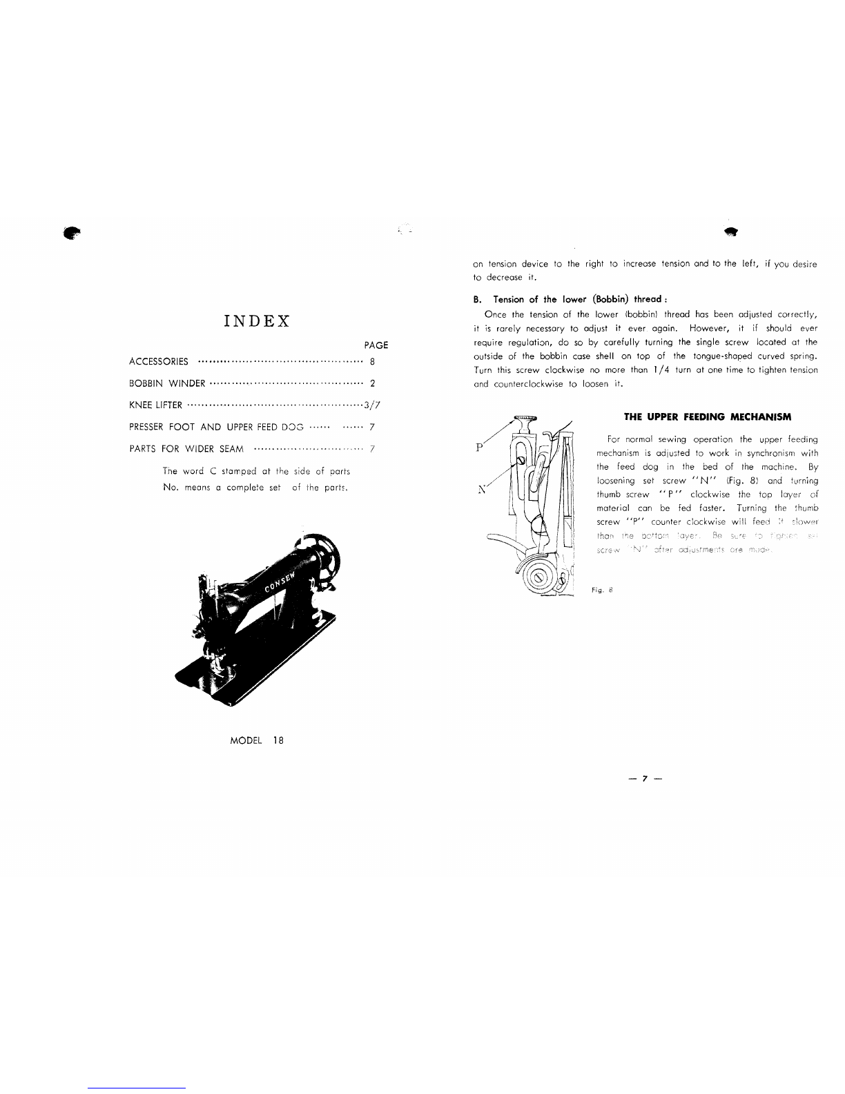
A.
Tension
of the upper
(Needle)
thread:
Before adjusting the tension
of
the upper (needle) thread, be certain that
the presser
foot
is
let
down
and not in
lifted
position Turn serrated nut
'S"
- 6 -