CONTENTS
Operation
instruction
I.Brief
introduction
...............................................................................................
1
2.Main
specification
..............................................................................................
1
3.Preparation
.......................................................................................................
1
4.Lubrication
........................................................................................................
2
5.Trial
run
............................................................................................................
2
6.Installing
the
needle
..........................................................................................
3
7.Coordination
between
needle,
thread
and
sewing
material.
................................3
8.Adjustment
of
thread
tension
.............................................................................
3
9.Threading
.........................................................................................................
4
10.Adjusting
the
stitch
length
...............................................................................
4
.
I1.Adjusting
the
thread
take-up
of
needle
thread
..................................................
5
12.Adjusting
the
thread
tak-up
of
looper
thread
..................................................
5
13.Adjusting
the
thread
releasing
..........................................................................
5
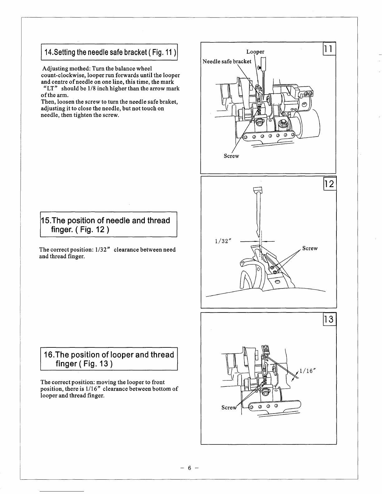
14.Setting
the
needle
safe
bracket
.........................................................................
6
15.The
position
of
needle
and
thread
finger
...........................................................
6
16.The
position
of
looper
and
thread
finger
...........................................................
6
17.Setting
the
position
of
fork
needle
.....................................................................
7
18.Timing
adjusting
for
fork
needle
......................................................................
7
19.Timing
adjusting
of
feed
dog
.............................................................................
8
Parts
Manual
1.Arm
and
bed
............................................................................................9-10
2.Needle
Bar,
Presser
foot
Part
.............................................................11-12
3.Needle
bar
moving,
presser
foot
lifting
bar
.................................... 13-14
4.Lower
shaft
part
..................................................................................15-16
5.Low feed,
looper
Part
.......................................................................... 17-18
6.Fork
needle
swing
shaft
part
..............................................................19-20
7.Preeser
bar,
pressure
cylinder
part
...................................................21-22
8.Threading
..............................................................................................23-24
9.Face
plate
................................................................................................25-26
10.Base
cover
part
....................................................................................27-28
11.
Accessories
..........................................................................................29-30


 User manual")