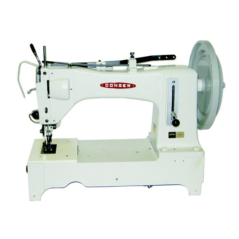
Consew 223 User manual

OPERATING
INSTRUCTIONS
FOR
MODELS
223,
223R
227,
227R
227B,
227BR
CONSOLIDATED
SEWING
MACHINE
A
U.S.INDU»rfllB«
CyMl^ANV.
From the library of: Superior Sewing Machine & Supply LLC

SPECIFICATIONS
SPEED
:Maximum 3000 r.p.m.
(With
reverse
stitch
mechanism
or
with synchronized binder 2800 r.p.m.)
NEEDLE:
135x17
HOOK
:Rotating
hook
STITCH
LENGTH
:
Maximum
5
mm
SIZE OF BED: 65^/>x269mm
MOTOR:
250W,
2P,
clutch
motor
DIAMETER
OF MOTOR
PULLEY
: 50 cycle 70 mm
60
cycle
60.mm
From the library of: Superior Sewing Machine & Supply LLC

CONTENTS
Setting up
the
machine 2
Speed
3
Oiling 3
Needle
and
thread
6
Inserting and removing
the
bobbin 6
Winding
bobbins
8
Threading
the
machine 9
Regulating
the
thread
tension
10
Regulating
the
pressure on
goods
11
Adjusting the stitch length 11
Adjusting the lift of
the
alternating presser feet 12
How to re-set the safety clutch mechanism 12
INFORMATION
FOR
ADJUSTMENT
Replacement of
the
timing belt 13
Adjusting
the
height of
the
feed
dog
14
Adjusting the timing of the needle plate, needle
and
feeder 14
Adjusting
the
height of
the
needle
bar
15
Timing
between
the
needle
and
hook
15
Relative position
between
bobbin case and
opener
16
Adjusting
the
height
of
the
presser
feet
16
Timing of the vibrating presser
foot
17
Adjusting
the
thread controller spring 17
Instructions
for 227B or 227BR
only
18
From the library of: Superior Sewing Machine & Supply LLC

SETTING
UP
THE
MACHINE
Before setting up
the
machine on
the
table,
attach
the
relative parts to
the
table.
1.
Motor
4.
Pedal
7.
Machine
base
10. V
shape
belt
2.
Stand
3.
Treadle
5. Machine rest pin 6.
Cotton
stand
8.
Head
9.
Chain
11.
Bobbin
winder
From the library of: Superior Sewing Machine & Supply LLC

SPEED
Maximum operating
speed
after a break-in period is 3000 stitches per minute
depending, of course, on the type of material being sewn, its thickness and
that of seams being crossed. (In case of the machine with reverse lever or
synchronized
binder
2800
r.p.m.)
To assure durability
and
trouble-free
operation,
it is
recommended
that
for
the
first several weeks of operation the maximum speed is held to not more
than 2400 RPM in order to allow the parts to become properly broken in.
in
operation
the
hand
wheel
of
the
machine always turn
toward
the
operator.
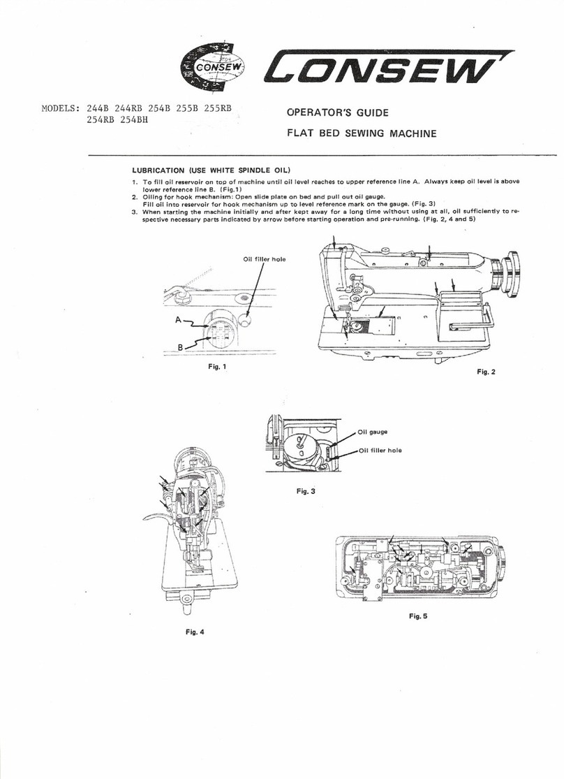
OILING
Do not
operate
the machine, even if only for testing, unless it has been
properly oiled at every
spot
requiring lubrication.
The
arrows
on the Figs. 2, 3, 4
and
5indicate
these
spots.
Oiling must be
done
at least
twice
daily
when
the
machine is in
continuous
operation
to assure free running
and
durability of
the
operating
parts.
The
hook
mechanism should receive careful
attention
when
lubricating
the
machine.
The oil well
beneath
the
hook
should
be filled with oil
and
the
felt
pad
in
the
same
should
be
soaked
with oil. in case of a
new
machine, oil
pad
every
time a
new
bobbin
is inserted.
From the library of: Superior Sewing Machine & Supply LLC

fl
iv
1
i\
From the library of: Superior Sewing Machine & Supply LLC

:/
-
From the library of: Superior Sewing Machine & Supply LLC

NEEDLE
The
machine
is
set
up
to
use
135x17
in
sizes ranging from 14 to 24.
The thickness of
the
sewing
thread,
which
must pass freely through the needle eye,
determines
the
size
of
the
needle.
To
insert
the
needle,
turn
the
machine
pulley
toward you
until
the needle bar (1)
raises to its highest point, loosen the needle
set screw (2), and put the needle up into
the
needle
bar as far as it will
go,
with
the
long groove of the needle toward the left,
and tighten the needle set screw securely.
Cotton, synthetic,
silk
thread can be used according to your sewing purpose,
the
thickness of
thread
available is up to
#8.
Only left twist thread is to be used for the needle, to test for twist, hold
a length of thread between thumbs and index
fingers
of your hands. Turn
the
thread
counterclockwise,
if it will twist tighter, it has a left twist.
If it
unravels,
it
has
aright
twist.
The bobbin can be
wound
with either left or right twist thread.
INSERTING
AND
REMOVING BOBBINS
(Figs.
8 and 9)
1. Raise the needle bar to its highest point. Push open the right-hand
cover plate (1,
Fig.
8) on the arm of the machine.
Pull up the latch (2,
Fig.
8) and lift the bobbin from the bobbin case.
In case of the binding machine with a synchronized binder, lift slightly the
serrated nuts (1,
Fig.
9) and pull open the plate (2,
Fig.
9) toward you.
2. To insert a full bobbin, hold it on one of its sides
between
thumb and
index finger of
your
right
hand.
Be
sure
that
the
thread
draws
out
from
the
bobbins
from left to right.
Place the bobbin on the center post of the bobbin case and push down the
latch
(2).
Pull the thread into the slot (3, Fig. 8) inside of the bobbin case and to
the
left
between
the
bobbin
case
opener
(4, Fig. 8) and a projection (5, Fig.
8)
and
under
the
tension spring (6, Fig. 8).
Draw
out
about
5 cm of
the
thread
on the
needle
plate
and
close
the
cover
plate, but leave sufficient space for passage of
the
thread.
From the library of: Superior Sewing Machine & Supply LLC

From the library of: Superior Sewing Machine & Supply LLC

WINDING
BOBBINS
The bobbin winder is mounted on the table
top
with its pulley in front
of the driving belt so that the pulley will separate from the belt after the
bobbin
has
been
wound
with
sufficient
thread.
Push the bobbin on bobbin spindle (1,
Fig.
10) as far as it will go. Pass
the
thread
from
thread
stand
downward
through
the
eye
in the tension
bracket.
Then
between
and
around
the
back
of
the
tension
discs, bring
the
thread
forward
toward
the
bobbin
and
wind
from
below
in
clockwise
direction
several
times
around
the
bobbin.
Push
bobbin
winder
lever (3, Fig.
10) downward until the wheel (2,
Fig.
10) contacts the drive belt and start
the
machine.
After
bobbin
is filled with
thread,
release will
cause
the
wheel
to disengage
from the belt and winding will stop.
Cut
the
thread
and
remove the
bobbin
from
the
winder
spindle.
The
adjustment
screw
(5, Fig. 10) can be
turned
in or
out
to increase or
decrease
the
amount
of
the
thread
wound
on
the
bobbin.
When fine thread is
wound
on bobbins, use light tension. It is regulated
by turning
the
knurled nut (6, Fig. 10) on the tension bracket at the rear of
the
bobbin
winder.
Bobbin can be
wound
while
the
machine is sewing.
If the thread does not wind evenly on bobbins, loosen the screw (4, Fig.
10) and move the bracket to the right or left as may be required, then
tighten
the
screw.
Fig. 10
— 8 —
From the library of: Superior Sewing Machine & Supply LLC

THREADING
THE
MACHINE
Raise
the
needle
bar
to its
highest
point.
From
the
thread
stand lead
the
thread
from back to front through
the
lower guide hole in the spool pin (1) on the top of the machine arm, then
again from right to left through the upper guide hole in this pin.
Pass the thread in weaving fashion through the three holes in the guide
(2), and from right to left over and between the tension discs (3). Now
pull the thread downward and from right to left beneath and around the
thread
controller (4),
continue
to pull the
thread
upward
against
the
pressure
of the wire spring into the fork (5) in the thread controller.
Guide upward through the thread guide (6) and from right to left through
the eye in the take-up lever (7), down through the thread guide (6) again
and then through (8), (9) and
(10)
from left to right through the eye of the
needle.
From the library of: Superior Sewing Machine & Supply LLC

REGULATING
THE
THREAD
TENSIONS
For ordinary stitching, the tension of the upper and lower threads should
be equal so as to lock
both
threads in the center of the fabric. If the
tension
on
either
thread
is
stronger
than
on
the
other,
innperfect stitching
will
be
the
result.
If the tension on the upper thread is greater than that on the lower thread,
it will be straight along the upper surface of the fabric.
If the tension on the lower thread is greater than that on the upper thread,
the
lower thread will lie straight along the underside of the fabric.
Fig. 13
Perfect stitching
^ Tight tension of needle thread
Loose
tension
of
needle
thread
Fig. 12
A.
TENSION
OF
THE
UPPER
THREAD
To adjust
the
tension of the
upper
(needle)
thread,
turn
the
serrated
nut
(1) to
the
right
for increasing tension. If
you
desire to de
crease
it,
turn
the
nut
to
the
left.
B.
TENSION
OF
THE
BOBBIN
THREAD
To
increase
the
tension,
turn
the
screw
(1)
to
the
right,
and
to
decrease
it turn
the
screw
to the left by a
screw
driver.
From the library of: Superior Sewing Machine & Supply LLC

ADJUSTMENT
OF
THE
PRESSURE
ON
GOODS
Fig.
]5
The pressure of the presser feet is
regulated by the adjusting screw (1, Fig.
2).To
increase
the
pressure,
turn
the
screw
to
the
right,
and
to
decrease
it
to
the
left.
ADJUSTING
THE
STITCH
LENGTH
[Numerals
on
pulley
jshow number of
:stitch per inch
~3
Stitch
length
(m/m)
Fig. 16
In
case
of
the
machine
without
reverse
lever, the length of the stitch Is adjusted
by turning the serrated knob (2,
Fig.
15).
It
will
be
noticed
that
there
is a
notch
(3,
Fig.
15) in this hub wherein appears
anumber. Same indicates the approxi
mate number of stitches per inch.
On
the
occasion
of
the
machine
with
reverse
stitch
mechanism,
it is
adjusted
by turning the serrated nut (1, Fig. 16)
so
that
the
reference
mark
on
the
collar
(3, Fig. 16) comes in line with
the
desired
number
of stitch length on
the
plate {2,
Fig. 16).
The numerical numbers on the plate
show
millimeter.
When
making reverse stitch, push
the
lever (4, Fig. 16) down as far as it will go.
From the library of: Superior Sewing Machine & Supply LLC

ADJUSTING
THE LIFT
OF
THE ALTERNATING PRESSER FEET
The thickness of
the
material sewn should control the height of
the
lift of
the
alternating presser feet.
It should normally be just high enough for clearance of the material. With
normal adjustment both feet lift to equal height.
To adjust the lift, loosen the wing nut (1), move up the nut to raise the
lift, and push down this nut to lower the lift.
When altering the lift of the lifting presser foot (4,
Fig.
7) unequally against
that of
the
vibrating presser foot (5, Fig. 7) or vice versa, see
the
instructions
"ADJUSTING
THE HEIGHT OF THE
PRESSER
FEET".
Fig. 17
HOW
TO
RE-SET
THE
SAFETY
CLUTCH
MECHANISM
The sewing hook and its mechanism are protected by a safety clutch. In
case the hook gets jammed with thread or other foreign matter, the safety
device disengages
the
driving belt, stops sewing, and thus prevents
the
machine
from getting
damaged.
If it
should
become
necessary to re-engage
the
safety clutch, depress
the
button
(2, Fig.
2) in
the
bed
plate, at
the
same time, turn
the
handwheel
away
from
you
until
the
lock
ing mechanism re-engages
the
driving
shaft
beneath
the
bed
of
the
machine,
open
the
slide plate
above
the
hook
and
rock
hand-
wheel back
and
forth to remove any foreign
matter
which
may have
lodged
in
the
hook.
Do not use any sharp-edged tools, lest
Fia.
18
the
hook
be damaged.
—
12
—
From the library of: Superior Sewing Machine & Supply LLC

REPLACEMENT
OF
THE
TIMING
BELT
1,
INSERTING
THE
BELT
Turn
the
hand
wheel
toward
you until the take-up lever reaches
to its highest point.
Turn
the
lower shaft (1, Fig. 19)
until
the
arrow
mark
on
the
lower
belt
pulley
(2, Fig. 19)
comes
in
line
with
another
arrow
on
the
timing plate (3, Fig. 19).
Insert a
new
timing
belt
into
the
belt pulley at this position.
2.
REMOVING
THE
TIMING
BELT
Move the machine top cover (2,
Fig.
3), remove the timing belt from the
belt pulley. Loosen the collar set screw (1, Fig. 20), draw
out
the feed
regulating dial (2, Fig. 15) from the arm shaft.
Loosen
the
two
set screws (4, Fig. 15),
draw
out
the
hand
wheel
(1, Fig.
15)
from
the
arm
shaft.
Loosen the set screw (1, Fig. 4) and draw
out
the rear bushing (2, Fig. 4)
through
the
arm hole.
Removing
and
inserting
the
timing belt is
made
through the hole
drawn
out
the
rear
bushing.
After inserting a
new
belt, replace
the
arm
top
cover,
screws
to their
original places securely.
Fig.
20
—
13
—
From the library of: Superior Sewing Machine & Supply LLC

ADJUSTING THE HEIGHT OF THE FEED
DOG
1 The
maximum
height of the feed dog (1)
j 1 from the surface of the needle plate (2) is
T / *
normally
1
mm.
(In
case
of
the
machine
with
I m the
synchronized
binder,
the
height
of the
feeder should be equal to the surface of
I
adjust
this
height,
turn
the
hand
wheel
so as to raise
the
feed dog to its highest
Draw
out
the
cylinder (4, Fig. 2).
p.
Loosen
the
set
screw
(3),
adjust
the
height
of
the
feeder by raising or lowering it.
Securely tighten the
screw
and replace
the
cylinder.
ADJUSTING
THE
TIMING
OF
THE NEEDLE PLATE,
NEEDLE
AND
FEEDER
Fig. 23
1.
RELATIVE
POSITION
OF
THE
FEEDER
TO
NEEDLE
PLATE
Adjust
the
feed
motion
to
the
maximum
and
loosen
the
screw
(4, Fig. 19).
Set
the
position of
the
feeder
so
that
both
clearances A
and
B(Fig. 22)
are
equal
before
starting feed motion and after finishing the
feed.
Securely
tighten
the
screw.
Fig. 22
2.
THE
POSITION
OF
THE
NEEDLE
AND
NEEDLE
HOLE
OF
THE
FEEDER
To adjust this, turn
the
hand
pulley to raise
the
needle bar to its highest point and put a perfect
needle.
Turning
the
hand
wheel
to
lower
slowly
the
needle
bar,
check
whether
the
needle
descends
to
the
center
of
the
needle
hole
of
the
feeder
or
not.
If
the
needle
does
not
enter
into
the
center
of
the
hole,
loosen
the
screw
(1, Fig. 23)
through
the
window
of
the
arm (5, Fig. 2).
Holding
the
bottom
of
the
needle
bar rock frame
(1,
Fig.
3) move it as may be required to get the
correct
position
to
the
feeder.
Then,
tighten
the
—
14
—
From the library of: Superior Sewing Machine & Supply LLC

ADJUSTING
THE HEIGHT
OF
THE NEEDLE BAR
1.
When
the
needle
bar
Is
at
its
highest
point,
normally
the
measurement
between
the
surface
of the
needle
plate
and
the
upper
end
of the
needle
eye is
21.1
mm
(in case of the
machine
with the synchronized binder, it is
19.3
mm).
To
adjust
this,
loosen
the
screw
(2,
Fig.
3),
move
the
setting
position
of
the
needle
bar
and
needle
bar
connecting
stud
(3,
Fig.
3)
to get the
correct
position. Then tighten
the
screw.
2.
There
is
another
method
for this
adjustment
by
setting
the
needle
bar
to its lowest point.
The
normal
position,
in
this
case,
is 4
mm
approximately
from
the
hook
point to the upper end of the needle eye.
NOTE:
These
measurements
are
approximate
standard,
accordingly,
following
final
adjustments
are
recommended.
TIMING
BETWEEN THE
HOOK
AND
NEEDLE
After setting the needle bar height as stated 1. or 2., confirm as follows:
Set the stitch length to 0, turn the hand wheel to lower the needle bar
to its
lowest
point, turn the hand wheel toward you.
When
the
needle
raises
1.9
mm
from
the
lowest
point
of
its
travel,
normally
the hook point is at the center of the needle and the measurement between
the hook point and the upper end of the
needle
eye
should
be
2.1
mm,
further the clearance between the hook point and the needle hollow should
be
about
0.05
mm
to
0.2
mm.
If they are not measured as above, adjustments are made as follows:
2.1mm
1.9mm
Fig. 24
—
15
—
From the library of: Superior Sewing Machine & Supply LLC

j'
1.
timing
adjustment
/'
ance
and
tighten
the
screws.
Fig.
25
Be
sure
to
use
perfect
needle.
RELATIVE
POSITION
BETWEEN BOBBIN CASE
AND
OPENER
1. Loosen the screw (1), turn the
hand
IR
,
wheel
until
the
opener
(2)
is
located
at
mV
I
the
extreme
right
hand
position
of
its
^clearance
between
the
inside
edge
^ 1
opener
and
the tab
on
the
bobbin
case
holder
is
about
0.2
mm.
HH[RBRRH|HRII| ^
After
the
adjustment,
tighten
the
screw.
ADJUSTING THE HEIGHT OF THE
PRESSER
FEET
1.
ADJUSTMENT
BY THE PRESSER BAR LIFTER
Loosen
the screw (1,
Fig.
2)
sufficiently,
raise
the presser bar
lifter
and
loosen
the
set
screw
{1, Fig. 27).
Move the
lifting
presser foot (4,
Fig.
7) up or down as may be required
so as to get the correct height and tighten the screw.
2.
ADJUSTING
THE LIFT OF ALTERNATING PRESSER FEET
On
the
model 227, 227R, 2278
and
227BR
if the height of the lifting
presser foot changes, the momentums of the
lifting
and vibrating presser foot
vary, thus the height of the vibrating presser foot must be adjusted.
A. Lower the presser bar lifter, holding the vibrating presser foot (5,
Fig.
7),
loosen the hexagon screw (2,
Fig.
27) and move the presser foot up or down
as may be required.
B. After setting the position, tighten
the
screw.
Normally, the momentums of the alternating presser feet are adjusted to
equal, but for piping work, it is effective to adjust less momentum of the
vibrating presser foot than that of the lifting presser foot.
From the library of: Superior Sewing Machine & Supply LLC

TIMING
OF
THE VIBRATING PRESSER
FOOT
This
is the
normal
timing
when, turn the balance wheel toward you, after
lowering the presser bar lifter, the vibrating presser foot should reach the
feeder earlier than the needle eye comes to, and when the needle raises,
the
vibrating
presser foot should
leave
the feeder after the needle eye has
left
the
feeder.
This is due to the reason that the vibrating presser foot must tightly hold
the goods while the needle is
passing
the goods for
avoiding
irregular
stitches.
To adjust this, set the lift of the alternating presser feet to equal, loosen
the two screws (3,
Fig.
27)
and adjust the rotating position of the cam (4,
Fig.
27) faster or slower as may be desired, and tighten the screw.
ADJUSTING
THE
THREAD
CONTROLLER
SPRING
Normally the thread controller spring (2,
Fig.
13) should hold slack of the
upper thread until the needle reaches to the goods, and it should pause
while raising of the needle and passing of the upper thread through the
bobbin
case.
For more controller action on the thread, loosen the stop screw (3,
Fig.
13)
and
move the stop (4,
Fig,
13) to the right.
For less action, set the stop to the left. Then tighten the screw.
To strengthen the tension of the spring, loosen the serrated nut (5,
Fig.
13), loosen the screw (6,
Fig.
13) and turn the tension stud (7,
Fig.
13)
slightly to the left with a screw driver, or to lighten the tension, turn to
the
right.
Then tighten
the
screw
and
nut.
From the library of: Superior Sewing Machine & Supply LLC

INSTRUCTION FOR THE MACHINES WITH SYNCHRONIZED BINDER
TAPING (Fig. 28)
Lift
the serrated two nuts
(1)
slightly and open the plate (2) toward you.
Pass
the tape
(3)
alternately
as
indicated
in
the
figure
(28)
through
the tape
guide (4).
Cut
obliquely
the
edge
of the tape and
pass
it
through
the
binder
(5)
and
draw
it
out
about
2
cm.
If
the tape
has
the
right
and
wrong
side,
pass
the tapethe
wrong
side
up.
Then, close
the
plate (2).
ADJUSTING THE BINDER (Fig. 28)
The setting position of the binder depends on the shape of the binder,
tape
width, thickness of goods.
Accordingly, it is determined through actual sewing test.
To adjust this, loosen the nut (1), move the binder to the right or left to
get
proper
position.
Then tighten the nut.
RELATIVE
POSITION
OF
THE
BINDER
TO
THE
FEEDER
0.2-
0.5mm
Adjust
the
clearance
between
the
feed
dog (1,
Fig.
29) and the binder (2, Fig.
29) from 0.2 to 0.5 mm. Tighten
the
screw
(6, Fig. 28). Care must be
taken
that
the
part
(7, Fig. 28)
does
not
move
axially
when
tightening
the
screw.
Fig. 29
From the library of: Superior Sewing Machine & Supply LLC
This manual suits for next models
5
Table of contents
Other Consew Sewing Machine manuals

Consew
Consew CN3115RB-1 User manual

Consew
Consew 332 User manual

Consew
Consew P1541S-CC Technical manual

Consew
Consew 697CVF User manual

Consew
Consew 315R-2 Parts list manual

Consew
Consew 332R User manual

Consew
Consew 230 Manual

Consew
Consew 146RBL-1A User manual

Consew
Consew 146RBL-1A User manual

Consew
Consew 206RB-5 User manual