INDEX
1,
Briefintroduction·..
···············
..
····
..·..·..·..
··
....
·..
··
....
·..·..
··
....
··
....
·..·..·..·..·..·..
··
..·
....
·..·..
··
....
·1
2,
Main specification..
····
..·..·..··
....
·..··
....
·..·..·..·:..···..·..·..·..·..·..·..·..·..··
....
·..·..·..··
....
·..··
....
·..·..
·1
3,
Installation·
....
··
....
·..·..·..
··
..·
....
·..·..·..
··
..·
....
·..
··
....
··
....
··..·
....
·..·..·..·..
··
....
·..·..·..·..·..·..·..
··
....
·1
0).
Location
of
the machine
......................................................................................................
1
(2).
Install the arm and oil reservoir..·..·..·..·..··
..
·
....
·..··
~
·..··
....
·..·..··..·
....
··
....
·..··
....
·..·..··
....
·..··
....
·..
·1
(3).
Install the machine head
......................................................................................................
1
4,
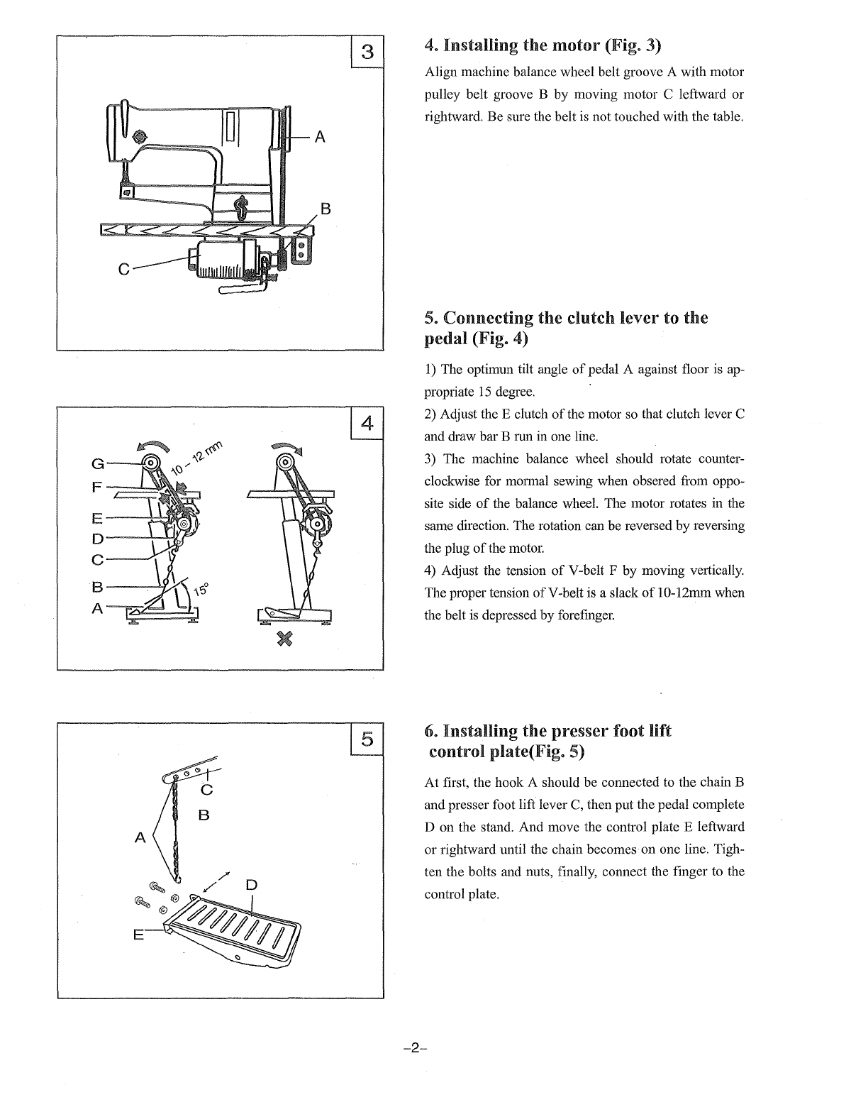
Installing motor
...............................................................................................................
2
5,
Connecting the clutch lever to the pedal
.................................................................................
2
6,
Installing the presser foot lift control
plate····:··
.......................................................................
2
7,
Installing the bobbin winder·
.............
·
.....
·..·..·
...............
···
.....
·..·
....................
·..·..·
...........
·...3
8,
Installing
the
thread
unwinder
.............................................................................................
3
9,
Preparation
................................................
···
......
·······
..................
···
..................................
3
(1). Cleaning the machine
.........................................................................................................
3
(2).
Examination
......................................................................................................................
3
10,
Lubrication
...................................................................................................................
4
11, Trial
run
.....................................................................................................................
4
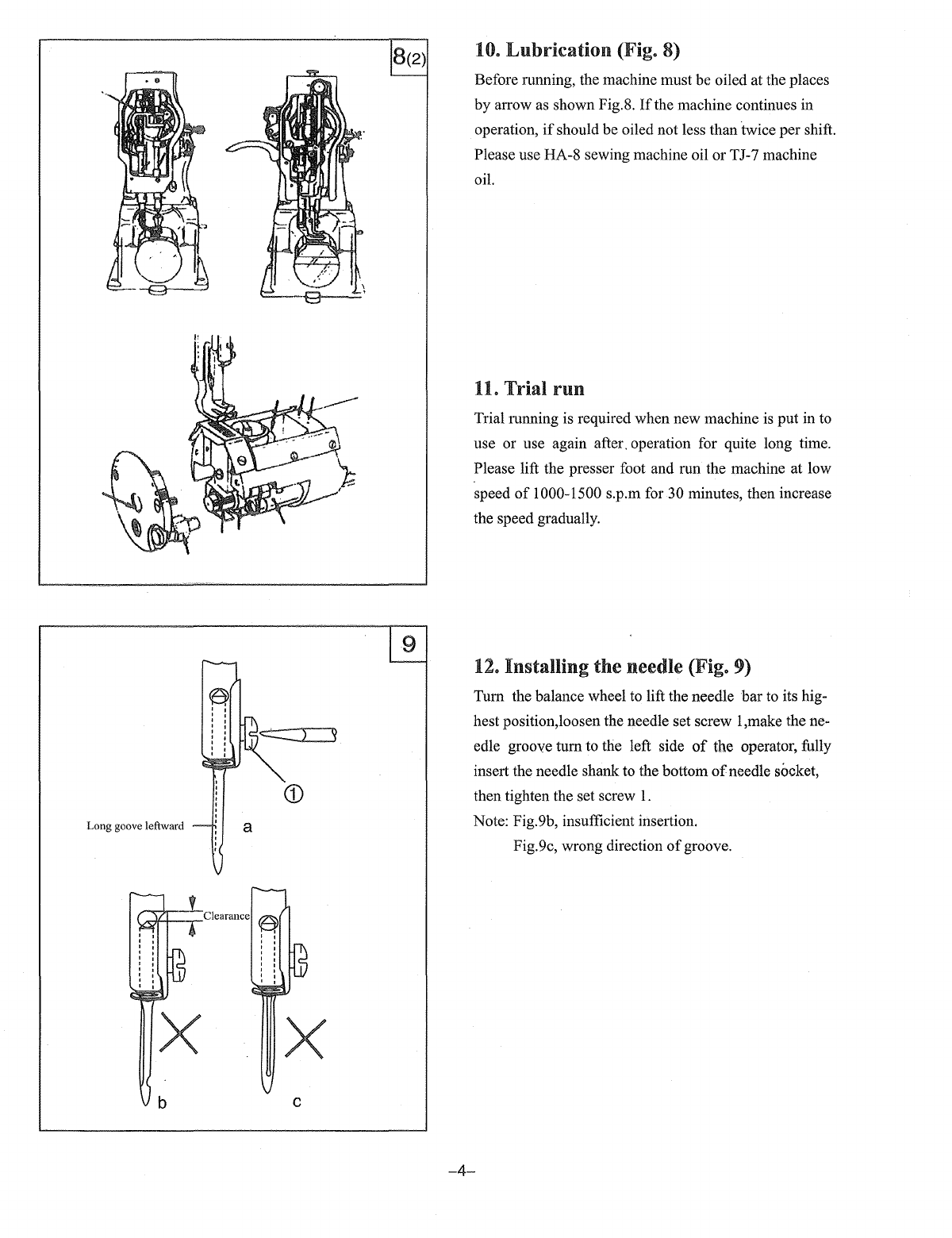
12,
Installing the needle···..
:·
..................................................................................................
4
13,
Coordination among the needle,the
thread
and
the material
..........................
;
...........................
5
14,
Threading
the
needle
thread
.............................................................................................
5
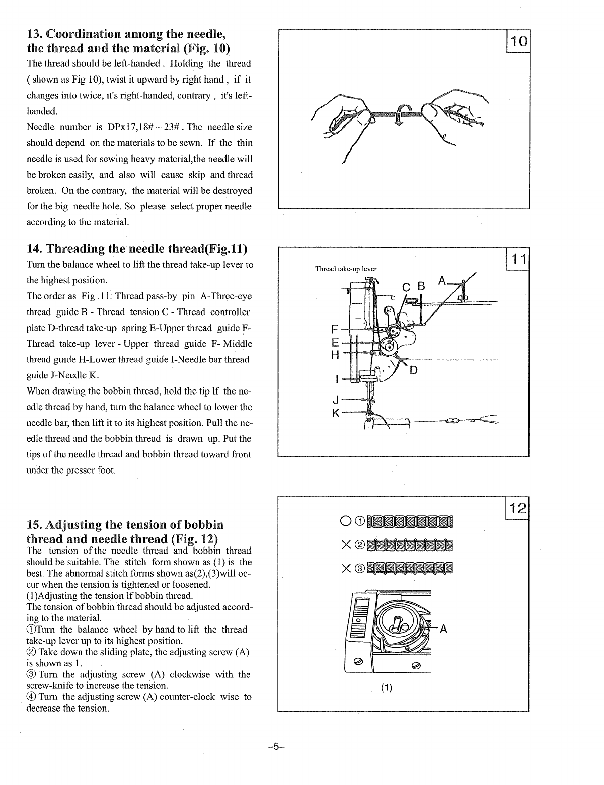
15,
Adjusting
the
tension
of
bobbin
thread
and
needle
thread
.........................................................
5
(1). Adjusting the tension
of
bobbin thread..·..·
..
··
..·
....
·..·..
··
....
·..
··
..·..".'..
··
....
·..·..·..·..·..·..•..····..·..·..·5
(2).
Adjusting the tension
of
needle thread·
....
·..·..··..·..·..····
....
·..·..··
....
·..·..·..·..·..··
....
··..·..·..·..·
....
·..·6
16,
Winding
the
bobbin
thread
and
adjustment
...........................................................................
6
17,
Stitch length
and
forward
and
backward feeding
................
·
......
·
......
·
....
·..·..·
................
··
......
7
18,
Adjusting presser foot pressure·
..........................................................................................
7
19,
The function
of
the safety clutch and its using
........................................................................
7
20, Adjusting the timing
offeed
..............................................................................................
8
21,
Adjusting the feed dog height position
.................................................................................
8
22,
Adustiong the timing
offeed
.............................................................................................
g
23, Adustiong the timing
of
needle
and
hook
..............................................................................
g
24, The relation between the hook
thread
sparate
bracket
...............
.-
............................................
10
25, Installing the hook··
.......................................................................................................
10
From the library of: Superior Sewing Machine & Supply LLC