LED indicator/fault pattern /
LED indicator/fault pattern
Cause /
Cause
Measures /
Measures
Green LED does not light up /
Green LED does not light up
Voltage interruptions /
Voltage interruptions
Ensure there is a stable power
supply without interruptions /
Ensure there is a stable power
supply without interruptions
Green LED does not light up /
Green LED does not light up
Sensor is faulty /
Sensor is faulty
If the power supply is OK,
replace the sensor /
If the power supply is OK,
replace the sensor
Yellow LED flashes /
Yellow LED flashes
Sensor is still ready for opera‐
tion, but the operating conditi‐
ons are not ideal /
Sensor is still ready for opera‐
tion, but the operating conditi‐
ons are not ideal
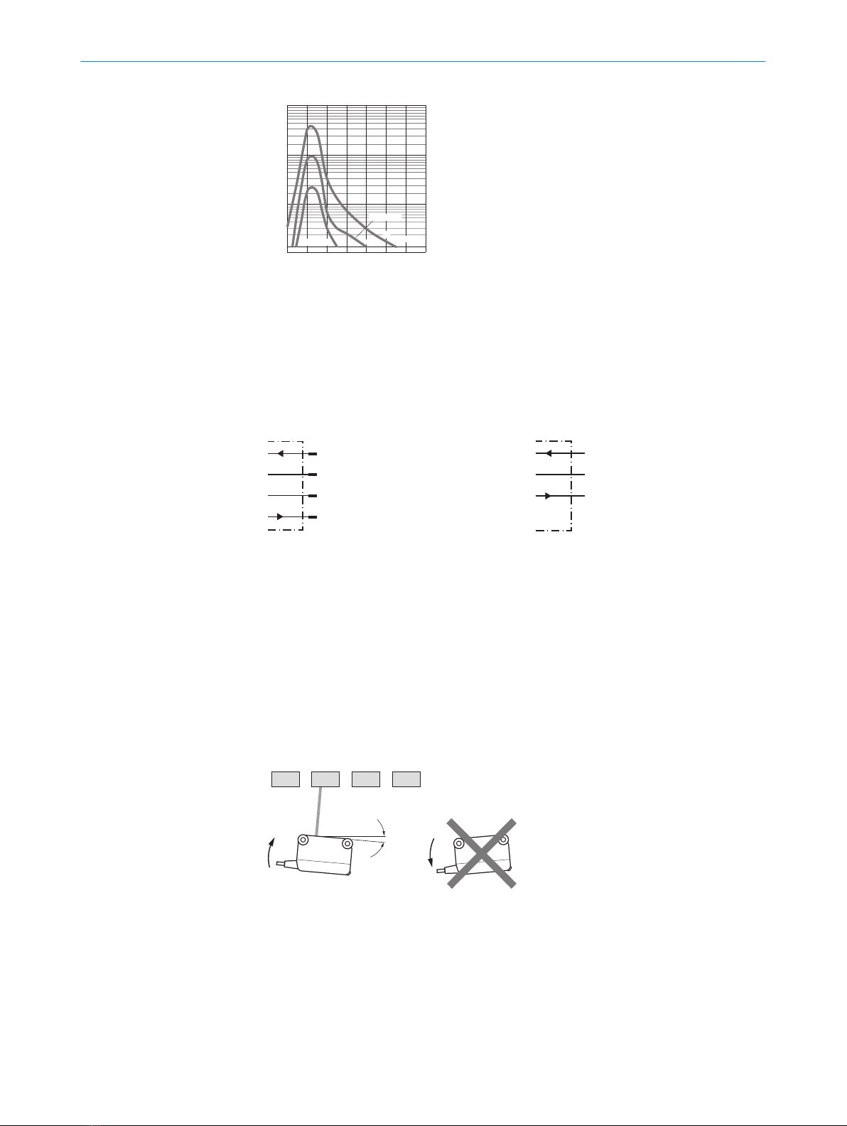
Check the operating conditi‐
ons: Fully align the beam of
light (light spot) with the
object. / Clean the optical sur‐
faces . / Readjust the sensiti‐
vity (potentiometer) / Check
sensing range and adjust if
necessary; see graphic F. /
Check the operating conditi‐
ons: Fully align the beam of
light (light spot) with the
object. / Clean the optical sur‐
faces . / Readjust the sensiti‐
vity (potentiometer) / Check
sensing range and adjust if
necessary; see graphic F.
Yellow LED lights up, no object
in the path of the beam /
Yellow LED lights up, no object
in the path of the beam
Remission capability of the
background is excessive /
Remission capability of the
background is excessive
Check changes to the back‐
ground. Reduce the sensitivity
of the sensor or use sensors
with background suppres‐
sion /
Check changes to the back‐
ground. Reduce the sensitivity
of the sensor or use sensors
with background suppression
Object is in the path of the
beam, yellow LED does not
light up /
Object is in the path of the
beam, yellow LED does not
light up
Sensitivity is set too low or dis‐
tance between the sensor and
the object is too long /
Sensitivity is set too low or dis‐
tance between the sensor and
the object is too long
Increase the sensing range,
take note of the distance bet‐
ween the sensor and the
background, see graphic F /
Increase the sensing range,
take note of the distance bet‐
ween the sensor and the
background, see graphic F
Object is in the path of the
beam, yellow LED does not
light up /
Object is in the path of the
beam, yellow LED does not
light up
Remission capability of the
object is insufficient /
Remission capability of the
object is insufficient
Increase the sensing range,
take note of the distance bet‐
ween the sensor and the
background, see graphic F /
Increase the sensing range,
take note of the distance bet‐
ween the sensor and the
background, see graphic F
7 Disassembly and disposal
The sensor must be disposed of according to the applicable country-specific regulati‐
ons. Efforts should be made during the disposal process to recycle the constituent
materials (particularly precious metals).
7 DISASSEMBLY AND DISPOSAL
48015312 | SICK
Subject to change without notice