Contracor CAB-110S Operating instructions

CONTRACOR GmbH
42327 Wuppertal Germany Art. 10115105/10115106
CAB-110S/CAB-135S
OPERATING AND MAINTENANCE MANUAL
Version 4.2

2
Table of contents
1. Safety 3
2. Package and description 4
3. General information 10
4. Set-up, operation and shut-down 12
5. Maintenance 20
6. Troubleshooting 25
7. Replacement parts 29
ATTENTION!
READ AND FULLY UNDERSTAND THIS MANUAL BEFORE STARTING WORK.
THE FOLLOWING INFORMATION IS IMPORTANT FOR SAFETY AND HEALTH
OF OPERATOR AND PERSONNEL IN VICINITY.
ATTENTION!
BUYING THE MACHINE, PLEASE, REQUEST TO FILL IN THE GUARANTEE
CARD CORRECTLY!
FAILURE TO PRODUCE A FILLED-IN FORM WILL MAKE YOUR GUARANTEE
INVALID.
EN

3
1. Safety
ATTENTION!
SAFETY MEASURES FOR BLAST CABINET OPERATION.
1. You must wear protective gloves during abrasive blasting.
2. Do not use worn or damaged equipment during operation.
3. Point the nozzle only at the area to be cleaned. Never point the nozzle
toward the cabinet windows.
4. Use only dry well-sieved abrasive materials, appropriate for abrasive
blasting operations.
5. Before starting of blast cabinet operation you must:
6. During blasting process all doors on the cabinet, reclaimer or dust col-
lector must be closed.
7. After blasting, before the doors are opened and exhauster is switched
off, use the blow nozzle to blow media from the blasted parts.
8. Do not open the doors or switch off exhauster before the cabinet is
clear of abrasive dust.

4
2. Package and description
15 14
16
17
13
12
10
9
7
6
11
8
5
4
3
1
2
Picture 2.0.1. Cabinet componets overview CAB-110S/135S (Front view)

5
19 18
20212223
24
25
26
27
29
30
31
28
32
Picture 2.0.2. Cabinet componets overview CAB-110S/135S (Back view)
Pos. No Description
1 Conveying hose Ø 100
2 Airline Filter
3 Pressure regulator, pilot operated

6
4 Pressure gauge
5 Air blow-off nozzle, rubber
6 Rubber hose for air blow-off nozzle
7 GX Manual blast gun
8 Blast media hose, transparent
Rubber air hose
10 RGS Blast cabinet gloves
11 Cabinet door latch
12 Pressure regulator, working pressure
13 Panel mounting pressure gauge, working pressure
14 Double pushbuttons ON / OFF
15 Main switch 0-I
16 Viewing window (assembly)
17 Pneumatic foot pedal
18 Door interlock
Electric motor
20 Ventilation hose Ø 150
21 Diaphragm pulse-jet valve
22 Electronic timer for pulse-jet valve
23 Pressure regulator, pulse-jet cleaning
24 Pressure gauge
25 Pulse-jet cleaning manifold
26 Reclaimer assembly R-350 / R-400
27 Screen
28 Reclaimer door latch
Filter cartridge
30 Metering valve, blast media
31 Dust container
32 Impeller for DC-1100 / 1500

7
Picture 2.0.3. Blast cabinet overall dimensions CAB-110S/135S
1990
1390
1240
688
840
450
502
Door
opening
849
890...934
680
1910
890...934
2205
988
1000
645
847
Door
opening
2160
1490 1770
840
410

8
Order code Model Description, package
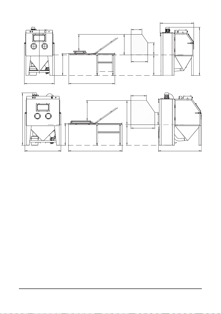
15105 CAB-110S BLAST CABINET, COMPLETE SYSTEM, CONSIST
- Cabinet Enclosure
- Cyclone reclaimer R-350
- Cartridge Dust Collector DC-1100 (see. Table 2.2.)
STANDARD DELIVERY:
- Quality 800 mm blast gloves with inner fabric lining
- Manual suction blast gun GX
- GXT-8,0 tungsten carbide gun nozzle Ø 8mm
- Reclaimer metering valve
- Pilot regulated blast pressure
- Door safety interlocks
Electrical connection 1,10 kW, 380V, 3 phase, 50Hz
Working chamber size (W x D x H) 1100 x 800 x 840
Weight, 350 kg
Noise level, 80 .. 120 dB (2000/14EC)
Standard load capacity, 350 kg
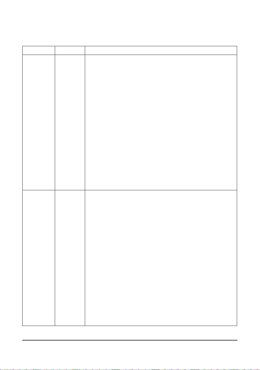
15106 CAB-135S BLAST CABINET, COMPLETE SYSTEM, CONSIST
- Cabinet Enclosure
- Cyclone reclaimer R-400
- Cartridge Dust Collector DC-1500 (see. Table 2.2.)
STANDARD DELIVERY:
- Quality 800 mm blast gloves with inner fabric lining
- Manual suction blast gun GX
- GXT-8,0 tungsten carbide gun nozzle Ø 8mm
- Reclaimer metering valve
- Pilot regulated blast pressure
- Door safety interlocks
Electrical connection 1,50 kW, 380V, 3 phase, 50Hz
Working chamber size (W x D x H) 1350 x 1100 x 1070
Weight, 450 kg
Noise level, 80 .. 120 dB (2000/14EC)
Standard load capacity, 350 kg
2.1 Package
Table 2.1

Table 2.2
Filtering media
Filtering surface,
m2
Fan power,
kW
Fan capacity,
m3/h
Fan pressure,
Pa
CAB-110 Polyester 7,5 1,1 1050
CAB-135 Polyester 11 1,5 1150 2250

10
3. General information
3.1. General information.
blast cleaning while maintaining a clean surrounding work area.
Production rates of the blast cabinets are dependent on size of nozzle, compressor
capacity, working pressure, type and size of abrasive media and distance between the nozzle
and the cleaning surface.
Contracor suction type blast cabinets consist three modules:
1. Ruggedly built welded steel cabinet enclosure.
3.2. Theory of operation.
When the air supply is on, and the cabinet doors are closed, the blast machine is
ready for operation by actuating the foot pedal. Fully depressing the foot pedal causes air
mixing chamber. The media mixes with the air and is propelled out the nozzle.
products generated by blasting, fall through the mesh screen into the cabinet hopper. These
from the reusable blast media. Next, the media is screened of oversize particles, and held
When the foot pedal is released, the blasting stops.
expanding against the inner surface of the cartridge. An electronic timer controls the time

11
Table 3.1 Compressed air requirements
3.4. Blast media.
manufactured for dry blasting.
Steel blast media: Still grit or shot can be limited used with CAB-110S and CAB-135S
cabinets (max. mesh size ca. 0,80 mm). Rubber curtains should be used to protect the cabinet
walls from rapid wear.
Sand and Slag: Sand should never be used because of the respiratory hazards
associated with the use of using media containing free silica.
cartridge to release dust accumulated on the outer surface. The dust particles fall away
from the cartridge and into the hopper for removal.
3.3 Air jet diameter and required compressed air volume.
of maximum performance.
The size of the compressor required to operate the cabinet depends on the size of the
air jet and blasting pressure. See table 3.1 Compressed air requirements.
In standard delivery cabinets are shipped with the suction blast gun GX equipped with
Ø4mm air jet and Ø8mm blast nozzle.
Ø
Air jet
(mm)
Ø
Blast
nozzle
(mm)
REQUIRED AIR VOLUME (m³/min.)
at working pressure, bar
234567810 12
3,2 6,0 0,245 0,326 0,406 0,487 0,568 0,730 1,050
4,0 8,0 0,436 0,723 0,865 1,010 1,150 1,300 1,585 1,870
5,0 10,0 0,681 1,130 1,350 1,580 1,800 2,030 2,480

12
ATTENTION!
Abrasive blasting with sands containing crystalline silica can cause seri-
ous or fatal respiratory disease.
Slags are not recommended because they rapidly breakdown.
Aluminum Oxide, Silicon Carbide, and Garnet: Aggressive media such as these may
be used but consideration should be given to accelerated wear on any part of the cabinet,
reclaimer, nozzle and hoses which comes in contact with the media.
In case of using of an aggressive blast media a tungsten carbide nozzle have to be used.
Service life of the tungsten carbide nozzle lasts 10 to 20 times longer than ceramic.
Glass Beads:
moderately high humidity conditions. Glass beads subjected to excessive moisture may be
reused after thorough drying and breaking up of any lumps.
3.5 Compressed air quality
problems persist, an air dryer may be required.
4. Set-up, operation and shut-down
4.1. Installation and Set-up.
4.1.1 Location
Select a location where compressed air, water and electrical service are available.
4.1.2 Compressed air supply line
Connect compressed air supply line with min. I.D. = ½”. to the cabinet inlet. For

13
4.1.3 Grounding
Ground the cabinet to prevent static electricity build up. For grounding attach an
external grounded wire to the grounding lug on the cabinet skirt.
4.1.4 Electrical power connection
ATTENTION!
blast cabinet. Hose disconnection while under pressure could cause seri-
ous injury.
ATTENTION!
to the national and local standards.
A wiring schematic is supplied with the cabinet. After wiring is completed, check the
motor rotation by momentarily turn switch on and off. The motor will slowly turn. Check
the rotation of the motor fan through the slots in the motor housing. The fan should rotate
clockwise when viewed from the fan end to the motor.
ATTENTION!
Do not look into the reclaimer exhauster outlet while the exhauster is
turning. Injury to the eye or face could occur from objects being ejected
from the exhauster.
4.1.5 Cabinet static pressure
Cabinet static pressure must be set to match the cabinet dimensions and reclaimer
sizes. Open the inlet damper further to decrease static pressure or close it further to
increase pressure.
Use the gloves as an indicator of right cabinet static pressure. With the exhauster on,

14
4.1.6 Foot pedal
Blast cabinet is designed for one-person operation. Be sure you can quickly remove your
foot from the pedal in an emergency.
4.2. Blasting operation
4.2.1 Media loading
With the exhauster off, add clean dry media, by pouring it into the reclaimer hopper
4.2.2 Media unloading
To empty the cabinet of old media turn off the exhauster and place an empty
container under the metering valve. Unscrew the lower plug from the metering valve. Media
4.2.3. Parts loading and unloading
Parts may be loaded and unloaded through either door.
Blasted parts must be free of oil, water, grease, or other contaminants that will clog
interlock system will prevent blasting.
Table 4.1 The minimum amount of media to charge the system is as follows
CAB-110P CAB-135P
20 kg 40 kg

15
ATTENTION!
Always close cabinet, reclaimer and dust collector doors before blasting.
Keep all doors closed during blasting.
Always wear blast gloves.
Avoid pointing the blast nozzle toward the view window.
Use the blow-off nozzle to blow media off parts before opening doors.
After blasting, keep doors closed and exhauster on until the cabinet is
clear of all airborne dust.
Stop blasting immediately if dust leaks are detected.
4.2.4. Blasting operation
Open the compressed air supply to the blast cabinet. On the initial start up check for
air leaks. Adjust the pulse pressure regulator to 4,5 bar (see Picture 2 for location).
Push button ON to switch on the exhauster. Insert hands into rubber gloves. Firmly grasp
the blast gun and step on the foot pedal. Blasting will begin immediately. Adjust blast
pressure using pilot regulator located on the control panel. Pressure gauge on the control
panel shows actual blast pressure value.
Most effective blasting techniques are smooth continuous strokes. The distance from
the part affects size of blast pattern. Normal practice places the nozzle approximately 70 to
150mm from the surface of the part.
ATTENTION!
Shut down the cabinet immediately if dust discharges from the collector.
Prolonged breathing of any dust could result in serious lung disease
or death. Short term ingestion of toxic dust such as lead, poses an
immediate danger to health. Toxicity and health risk vary with dust
generated by blasting. Identify all material being removed by blasting, and
obtain a material safety data sheet for the media.

16
During the blast cabinet operation, dust collector is pulsed automatically according to
the timer settings. Prolonged periods of blasting or duty conditions may require adjustment
of the timer settings.
4.2.5. Stop blasting operation and shut-down.
To stop blasting, remove pressure on the foot pedal.
Use the air blow-off nozzle, to blow media off cleaned parts. Allow the exhauster to
clean the cabinet of airborne dust before opening the door and unload the parts. Push
button OFF to switch off the exhauster.
4.3. Adjusting
4.3.1 Blasting pressure
The pilot pressure regulator, located on the control panel of the cabinet, enables the
user to adjust the blasting pressure to suit the application.
The suitable pressure for most purposes is around 5-6 bar. Lower pressures may be
required on delicate substrates, and will reduce media breakdown. Higher pressure may be
In all cases, highest production can only be achieved when pressure is carefully monitored.
Adjust air pressure by turning the knob on the pilot regulator located on the front of
the control panel. Pull the knob out, and turn clockwise to increase pressure or counter-
clockwise to decrease. Once operating pressure is set, push the knob in to lock.
4.3.2 Air jet adjustment
The air jet should be screwed 4.5 to 5 full turns into the rear of the GX gun body.
Doing so will leave 3.5 to 4 threads exposed past the lock nut. Tighten the lock nut to hold
4.3.3 Media/Air Mixture
evenly through the hose.

17
Picture 4.3.3. Metering valve adjustment
Adjusting Screw
holes fully open
holes fully closed
smoothly, the metering valve requires adjusting.
To adjust loosen the locking nut, and adjust the metering screw until the hole in the
metering stem is half-closed.
If pulsation occurs in the media hose, either media is damp and caked, or not enough
air is entering the media stream. While blasting, loosen the locking nut and slowly turn the
air in the mixture by turning the metering screw in (clockwise when viewed from the top)
covering more of the hole so less air enters the media hose. Tighten the locking nut to
maintain the setting.
4.3.4 Reclaimer static pressure
Correct static pressure varies with size of reclaimer and the size, weight and type of
media. Adjust reclaimer static pressure by opening (handle horizontal) or closing (handle
vertical) the damper on the dust collector inlet.
in dusty media, poor visibility, and possible media blockage in the conveying hose. If the
damper is opened too far, it may cause carryover (usable media carried into the dust
collector) and result in excessive media consumption. Open only as far as necessary to
obtain a balance of dust removal without media carryover.

18
ATTENTION!
Never attempt to override the interlock system.
Doing so could result in injury from unexpected blasting.
Interlock
switch
Cabinet door
Actuator
Picture 4.3.6. Actuator
adjustment
4.3.5 Cabinet static pressure
Once the inlet is initially set per section 4.1.5, it seldom requires readjustment.
The initial setting produces approximately 50% to 75% of static pressure in the cabinet
enclosure. For adjustment open the inlet damper further to decrease static pressure or
close it further to increase pressure.
Use the gloves as an indicator of right cabinet static pressure. With the exhauster on,
4.3.6 Door Interlocks
The door interlocks disable the blasting control circuit when the doors are open. To enable
blasting, the door interlock switches must be engaged when the doors are closed. The interlocks
To adjust the actuator, bend it by hand as required for engaging the switch by full
closed door.
Test the operation with the doors both open and closed. Point the nozzle away from
the door when it is tested, and only open the door enough to disengage the interlock switch.

The interlocks should stop the blasting when the doors are opened, and permit blasting
when the doors are closed.
NOTE:
should be performed with the exhauster on.
4.3.7 Pulse pressure
Adjust pulse pressure using the regulator mounted on the pulse manifold. Begin pulse
pressure setting at 4,5 bar.
When pulsing alone does not adequately clean the cartridge, increase pulse pressure
by 0,5 bar increments up to max. 6,0 bar. Increasing pulse pressure over 6,0 bar may cause
and differential pressure increase, adjust cycling of the pulses.
4.3.8 Timer
Adjust pulse time and cycling on the timer
(see Picture 2 for location).
Use ON scale to adjust the pulse length and
OFF scale to adjust the time period between the
pulses.
Begin setting is as follows:
Pulse length (ON scale) - 60 ms (by 4.5 bar
pulse pressure).
Time between pulses (OFF scale) - 5 min Picture 4.3.8.Pulse time and
cycling adjustment

20
5. Maintenance
5.1. Preventive maintenance.
5.1.1 GX manual blast gun
Inspect the GX manual blast gun for wear. Replacing the air jet cover before it wears
through will prolong the life of the jet.
5.1.2 Dust container
Empty the dust container regularly. Start by checking the container at least daily or when
adding media, then adjust frequency based on usage, contamination and friability of the media.
5.1.3 Reclaimer debris screen
The screen is accessible through the reclaimer door. With the exhauster off, remove the
screen and empty it daily or when loading media. Empty the screen more often if parts being
blasted causes excessive debris. Do not operate the machine without the screen in place.
once a day, more often if required, or if water mist is seen coming out the nozzle.
air dryer may be required.
5.1.5 Media Hose
To avoid unscheduled down-time, inspect the media hose for thin spots, especially
along an outside radius.
5.1.6 Changing the rubber shield of the reclaimer
A rubber shield (3) is installed to prevent damage to the walls of the reclaimer (1),
caused by abrasive particles when the abrasive-air mixture enters the reclaimer. It should
Other manuals for CAB-110S
1
This manual suits for next models
3
Table of contents
Other Contracor Industrial Equipment manuals
Popular Industrial Equipment manuals by other brands

Eaton
Eaton Airflex WCB Series Installation, operation and maintenance

SilverBolt
SilverBolt Mug Pro 5 user manual

Mechatron
Mechatron ATC-8022-30-HSK25 operating manual

ZKTeco
ZKTeco OP1000 Series user manual

Rittal
Rittal CP 6206.025 Assembly and operating instructions

Minebea Intec
Minebea Intec Inteco PR 6203 installation manual