Trinity Highway QuadGuard Elite M10 Wide User manual


QuadGuard
®
is a registered trademark of Energy Absorption Systems, Inc.
Part No. 626821
© 2020 Trinity Highway Products, LLC
TrinityHighway.com 1 Revision A August 2020
QuadGuard® Elite M10 Wide [69”]
The QuadGuard
®
Elite M10 Wide has been tested pursuant to American Association of State
Highway and Transportation Officials (“AASHTO”) Manual for Assessing Safety Hardware
(“MASH”) specifications. The QuadGuard
®
Elite M10 Wide has been deemed eligible for federal-aid
reimbursement on the National Highway System by the Federal Highway Administration (“FHWA”).
Product Description
Assembly Manual
2525 N. Stemmons Freeway
Dallas, Texas 75207
Warning:
The local highway authority, distributors, owners, contractors,
lessors, and lessees are RESPONSIBLE for the assembly, maintenance, and
repair of the QuadGuard
®
Elite M10
Wide
. Failure to fulfill these
RESPONSIBILITIES with respect to the assembly, maintenance, and repair
of the QuadGuard
®
Elite M10
Wide
could result in serious injury or death.
Important:
These instructions are for standard assembly specified by the
appropriate highway authority. In the event the specified system assembly,
maintenance, or repair would require a deviation from standard assembly
parameters, contact a Trinity Highway representative. This system has been
deemed eligible by the FHWA for use on the national highway system under strict
criteria utilized by that agency.
This manual must be available to the worker overseeing and/or assembling the product at
all times. For additional copies, contact Trinity Highway directly at (888) 323-6374 or visit
TrinityHighway.com.
The instructions contained in this manual supersede all previous versions. The instructions,
illustrations, and specifications are based on the latest QuadGuard
®
Elite M10
Wide
information
available to Trinity Highway at publication. We reserve the right to make changes at any time.
Please visit TrinityHighway.com/Product/QuadGuard-Elite-M10/ to confirm the latest revision.

TrinityHighway.com 2 Revision A August 2020
Table of Contents
Customer Service Contacts..........................................................................................................3
Important Introductory Notes ........................................................................................................3
Safety Symbols.............................................................................................................................4
Safety Rules for Assembly............................................................................................................4
Limitations and Warnings..............................................................................................................5
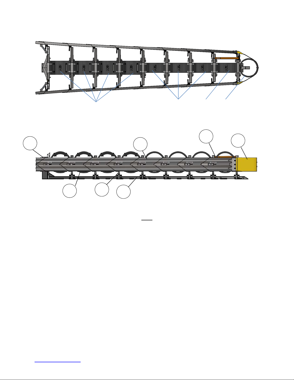
System Overview..........................................................................................................................6
Inspect Shipping......................................................................................................................6
System Components...............................................................................................................7
Select Transition ...................................................................................................................11
Recommend Tools......................................................................................................................12
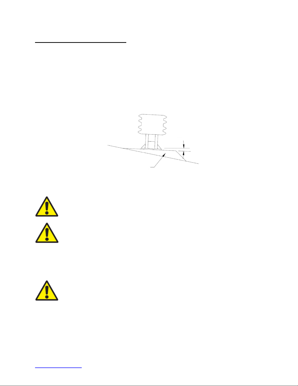
Site Preparation/Foundation.......................................................................................................14
Foundation/Anchoring...........................................................................................................15
Trinity Highway Approved Adhesive Anchoring System.............................................................16
Vertical Anchors....................................................................................................................16
Steel Rebar Anchor Assembly Cautions...............................................................................17
Horizontal Anchors................................................................................................................18
System Assembly .......................................................................................................................21
QuadGuard®Elite M10 Wide Final Inspection Checklist.............................................................37
Maintenance and Repair.............................................................................................................38
Visual Drive-By Inspection....................................................................................................38
Walk-Up Inspection...............................................................................................................38
Maintenance Flow Chart.............................................................................................................40
Post-Impact Instructions........................................................................................................41
Parts Ordering Procedure and Drawings....................................................................................44
QuadGuard®Elite M10 Wide QGEMTSCVR8-U69...........................................................46
Backup Assembly, Tension Strut627528...........................................................................47
Bay 1 Diaphragm Assembly627506.................................................................................48
Standard Diaphragm Assembly627506............................................................................49
Fender Panel Assembly608240 ........................................................................................50
Cylinder Attachment618879.............................................................................................51
Nose Assembly627505.....................................................................................................52
Hit Indicator610237...........................................................................................................53
Monorail Assembly625637...............................................................................................54
TS Concrete Pad618686...................................................................................................55
TS Concrete Pad 8” w/Rebar618686 ................................................................................56
TS Concrete Pad 8” wo/Rebar618686 ..............................................................................57
31” W-Beam TransitionQFEMTSCVR-TWLR....................................................................58
Thrie-Beam TransitionQFEMTSCVR-TTLR......................................................................59
4” Safety Shape TransitionQFEMTSCVR-T4LR ..............................................................60
4” Safety Shape Flared TransitionQFEMTSCVR-T4LRF..................................................61
6” Single Slope TransitionQFEMTSCVR-T6LR................................................................62
6” Single Slope Flared TransitionQFEMTSCVR-T6LRF ...................................................63
End Shoe TransitionQFEMTSCVR-ESLR........................................................................64

TrinityHighway.com 3 Revision A August 2020
Customer Service Contacts
Trinity Highway is committed to the highest level of customer service. Feedback regarding the
QuadGuard
®
Elite M10
Wide
system, its assembly procedures, supporting documentation, and
performance is always welcome. Additional information can be obtained from the contact
information below:
Trinity Highway:
Telephone: (888) 323-6374 (USA)
+1 312 467 6750 (International)
Contact Link TrinityHighway.com\Contact
Important Introductory Notes
Proper assembly of the QuadGuard
®
Elite M10 Wide system
is critical to achieve performance
that has been evaluated and deemed eligible by the FHWA per AASHTO MASH criteria. These
instructions should be read in their entirety and understood before assembling the QuadGuard
®
Elite M10 Wide. These instructions are to be used in conjunction with the assembly of
QuadGuard
®
Elite M10 Wide
and are for standard assemblies only as specified by the applicable
highway authority. If you need additional information, or have questions about the QuadGuard
®
Elite M10 Wide, please contact the highway authority that has planned and specified this
assembly and, if needed, contact Trinity Highway Customer Service. This product must be
assembled in the location specified by the appropriate highway authority. If there are deviations,
alterations, or departures from the assembly protocol specified in this manual, the device may not
perform as tested.
Important:
DO NOT use any component part that has not been specifically
approved for this system during the assembly or repair of this system.
This product has been specified for use by the appropriate highway authority and has been
provided to that user who has unique knowledge of how this system is to be assembled. No
person should be permitted to assist in the assembly, maintenance, or repair of this system that
does not possess the unique knowledge described above. These instructions are intended for an
individual qualified to both read and accurately interpret them as written. These instructions are
intended only for an individual experienced and skilled in the assembly of highway products that
are specified and selected by the highway authority.
A manufacturer’s drawing package will be supplied by Trinity Highway upon request. Each
system will be supplied with a specific drawing package unique to that system. Such drawings
take precedence over information in this manual and shall be studied thoroughly by a qualified
individual who is skilled in interpreting them before the start of any product assembly.

TrinityHighway.com 4 Revision A August 2020
Safety Symbols
This section describes the safety symbols that appear in thisQuadGuard
®
Elite M10 Wide manual.
Read the manual for complete safety and assembly information.
Symbol Meaning
Safety Alert Symbol:
Indicates Important, Caution, Warning, or Danger. Failure
to read and follow the Important, Caution, Warning, or Danger indicators could
result in serious injury or death to workers and/or bystanders.
Warning:
Read safety instructions thoroughly and follow the assembly directions
and suggested safe practices before assembling, maintaining, or repairing the
QuadGuard
®
Elite M10 Wide. It is the responsibility of the installer to follow the
instructions contained in this manual. Failure to comply with these warnings could
result in increased risk of serious injury of death in the event of a vehicle impact.
Important:
Please keep up-to-date instructions for later use and reference by
anyone involved in the assembly of the product.
Safety Rules for Assembly
* Important Safety Instructions *
This manual must be kept in a location where it is readily available to persons who are skilled and
experienced in the assembly, maintenance, or repair of the QuadGuard
®
Elite M10 Wide.
Additional copies of this manual are available from Trinity Highway by calling (888) 323-6374 or
by visiting TrinityHighway.com/Product/QuadGuard-Elite-M10/. Please contact Trinity Highway if
you have any questions concerning the information in this manual or about the QuadGuard
®
Elite
M10 Wide.
Warning:
It is the responsibility of the installer to use appropriate safety
precautions when operating power equipment, mixing chemicals, and when
moving heavy equipment or QuadGuard
®
M10 Wide components. Safety articles
including but not necessarily limited to work gloves, eye protection, safety-toe
shoes, and back protection should be used.
Warning:
It is the responsibility of the installer to use all safety measures
incorporating appropriate traffic control devices specified by the highway authority.
These measures must be used to protect all personnel while at the assembly,
maintenance, or repair site.
Warning:
Use only Trinity Highway parts on the QuadGuard
®
Elite M10 Wide for
assembly, maintenance, or repair. The use of component parts not specified herein
is strictly prohibited. The QuadGuard
®
Elite M10 Wide assembled with Trinity
Highway parts has been tested, approved, and accepted for state use by the
FHWA. A QuadGuard
®
Elite M10 Wide Assembly using parts other than those
specified herein has not been tested, approved, or accepted for state use by the
FHWA. Failure to follow this warning could result in increased risk of serious injury
or death in the event of a vehicle impact.

TrinityHighway.com 5 Revision A August 2020
Limitations and Warnings
Pursuant to MASH “Recommended Procedures for the Safety Performance of Highway Safety
Features”, Trinity Highway contracts with FHWA approved testing facilities to perform and
evaluate crash tests to prepare a crash test results report. Trinity Highway is then able to submit
a Request for Federal Aid Reimbursement of Safety Hardware Devices to the FHWA for review.
The QuadGuard®M10 Wide has been deemed eligible by FHWA as meeting the requirements
and guidelines of MASH. These tests evaluate product performance defined by AASHTO
involving lightweight cars (approx. 2420 lb. [1100 kg]) and full size pickup trucks (approx. 5000
lb. [2270 kg]). A product can be certified for multiple Test Levels. The QuadGuard®M10 Wide is
certified to the Test Level(s) as shown below:
Test Level 3: 62 mph [100 kph]
These AASHTO directed tests are not intended to represent the performance of systems
when impacted by every vehicle type or every impact condition existing on the roadway.
This system is tested only to the test matrix criteria of MASH as approved by FHWA.
Trinity Highway expressly disclaims any warranty or liability for injury or damage to persons or
property resulting from any impact, collision or harmful contact with products, other vehicles, or
nearby hazards or objects by any vehicle, object or person, whether or not the products were
assembled in consultation with Trinity Highway or by third parties.
The QuadGuard®Elite M10 Wide is intended to be assembled, delineated, and maintained within
specific state and federal guidelines. It is important for the highway authority specifying the use
of a highway product to select the most appropriate product configuration for site specifications.
The customer should be careful to properly select, assemble, and maintain the product. Careful
evaluation of site layout, traffic speed/type, direction, and visibility are some of the elements that
require evaluation by the highway authority in the selection of a highway product. For example,
curbs could cause an untested effect on an impacting vehicle.
After an impact occurs, the debris from the impact should be removed from the area immediately
and the specified highway product should be evaluated and restored to its original specified
condition or replaced as the highway authority determines as soon as possible.
Warning: Do not assemble, maintain, or repair the QuadGuard®Elite M10 Wide
until you have read this manual thoroughly and completely understand it. Please
contact Trinity Highway if you do not understand these instructions (p. 3).
Warning: It is the responsibility of the installer to ensure that all Danger, Warning,
Caution, and Important statements within the QuadGuard®Elite M10 Wide manual
are completely followed. Failure to follow this warning could result in serious injury
or death in the event of a collision.

TrinityHighway.com 6 Revision A August 2020
System Overview
The QuadGuard®Elite M10 Wide is a potentially reusable, re-directive, non-gating crash cushion
for roadside features of 69” [1,753 mm]. It consists of energy-absorbing high density polyethylene
cylinders surrounded by a framework of Quad-Beam Panels.
Important: Trinity Highway makes no recommendation whether use or
reuse of any part of the system is appropriate or acceptable following an
impact. It is the sole responsibility of the project engineer and/or the local
highway authority and its engineers to make that determination. It is critical
that you inspect this product after assembly is complete to make certain that
the instructions provided in this manual have been strictly followed.
The QuadGuard®Elite M10 Wide utilizes three types of Cylinders in a “staged” configuration that
are designed and tested to address vehicles as defined by MASH for both lighter cars and heavier,
high center-of-gravity vehicles.
Impact Performance
The 8Bay QuadGuard®Elite M10 Wide has successfully passed MASH requirements stipulated
for Test Level 3 tests with both the light car and pickup trucks at speeds of up to 62 mph [100
kph] at angles up to 25 degrees.
During head-on impact testing, within MASH criteria, the QuadGuard®Elite M10 Wide has been
shown to telescope rearward to absorb the energy of impact. When impacted from the side, within
the applicable MASH criteria, it has been shown to redirect the vehicle back toward its original
travel path and away from the highway feature.
Warning: It is the sole responsibility of the project engineer and/or local highway
authority and its engineer to ensure that the delineation used for the QuadGuard®
Elite M10 Wide meet all federal, state, specifying agency, and local specifications.
Warning: It is the sole responsibility of the project engineer and/or local highway
authority and its engineer to ensure that the QuadGuard®Elite M10 Wide meets
all appropriate Manual on Uniform Traffic Control Devices (“MUTCD”) and local
standards.
Inspect Shipping
Check the received parts against the shipping list supplied with the system before deploying the
QuadGuard®Elite M10 Wide. Make sure all parts have been received (pp. 7 - 11).
Important: The manufacturer’s drawing package supplied with the QuadGuard®
Elite M10 Wide must be used with these instructions for proper assembly and
should take precedence over these general instructions.
Warning: Do NOT modify the QuadGuard®Elite M10 Wide in any way.

TrinityHighway.com 7 Revision A August 2020
System Components
Below is a list of system components that may be used in your particular QuadGuard
®
Elite M10
Wide configuration. Verify parts delivered and system details with the BOM (Bill of Materials) and
system drawings shipped with your system. Please call Trinity Highway if you have any system
questions (p. 3).
Note:
Components are not shown to scale.
Tension Strut Backup 69”
Diaphragm Assembly, QG Elite M10
627531 619120 - Varies
Panel, Side, QG, Wide Panel, Fender, QG Hinge Plate, Fender Panel
611900 611832 610172
Extension,Backup, M10, QGE Extension, Diaphragm, Angle Monorail Guide
618536 618526 611368

TrinityHighway.com 8 Revision A August 2020
Monorail, One Bay, QG Monorail, Three Bays, QG End Cap, Monorail, QG
611370 611379 608136
Flt St 3/16X2X13, W/ Holes Die Spring, 1 1/2 ODX3/4X6 Mushroom Washer
618652 117458 617045
Clamp, Nose Belt Nose Cylinder Plate
606330 612253
Belt Nose Assy QGE, 69 Nose Belt Hit Indicator Assembly
618870 605108 610237
Washer, 1/4X1 Washer, Flat 1/2X1 3/8 Washer, Flat, 5/8X1 3/4
118013 118009 003300

TrinityHighway.com 9 Revision A August 2020
Washer, Flat, 3/4X2 Washer, Lock, 3/8 Washer, Lock 1/2
118027 118092 118082
Washer, Lock, 5/8 Washer, Lock, 3/4 Nut, Hex 3/8, G2
118100 118089 115960
Nut, Hex 1/2 Rail Nut, Hex, 5/8 Nut, Hex, 5/8, A563A
115939 003340 003354
Nut, Heavy Hex, 3/4 Screw, HWH, 1/4X1, Tap Bolt, Hex, 3/8X3 1/2, AT, G5
003704 116891 113612
Bolt, Hex, 1/2X1, G5 Bolt, Hex 1/2X3, G2 Rail Bolt, 5/8X2, A307
113467 113476 003400

TrinityHighway.com 10 Revision A August 2020
Bolt, Hex, 5/8X3 1/2, G5 Bolt, Hex, 5/8X4, G5 Bolt, Hex, 5/8X5”, G5
113660 113666 113667
Flat Screw 5/8X8 1/2,G8 Bolt, Hex 5/8X9 A325 Bolt, Hex, 3/4X2, G8
116879 004489 113555
Bolt, Hex,3/4X5,G5,G Stud, 3/4X6 1/2, G5 Stud, 3/4X7, G5
113573 117540 117542
Cylinder Nose, HDPE, 28X20 Cylinder ME1 MASH Cylinder ME2 MASH
606689 618538 618649
Cylinder Assy ME3 MASH
Cylinder Segment, 18X9 1/2
Tel 1 3/4X1 3/4X12GA, G, 10”
618702 627504 615756

TrinityHighway.com 11 Revision A August 2020
Adhesive, HY200, Hilti Anchor Kit, Hilti 3/4X7 Tel 2X2X12GA, H2S, G, 10”
118710 619316 615765
Select Transition
Important:
A proper Transition Panel or Side Panel must be used on each side
of the Backup. A Side Panel is not needed when a Transition Panel is used.
Several types of transitions are available for use with the QuadGuard
®
Elite M10
Wide (Figures 1 – 6). The correct Panel(s) to use will depend on the direction of
traffic and what type of barrier or road feature the QuadGuard
®
Elite M10 Wide is
shielding. Contact Customer Service for any transition questions (p. 3).
Figure 1
No Transition
(Unidirectional only)
Figure 3
Single Slope Offset
Figure 2
Safety Shape Barrier
Figure 4
Vertical Barrier

TrinityHighway.com 12 Revision A August 2020
Recommend Tools
Documentation
Manufacturer’s Assembly Manual
Manufacturer’s Drawing Package
Personal Protective equipment
Eye Protection
Gloves
Safety Toe Shoes
Figure 5
Quad to Thrie-Beam
Figure 6
Quad to W-Beam Guardrail

TrinityHighway.com 13 Revision A August 2020
Cutting equipment
Rotary Hammer Drill
Rebar cutting bit
Concrete drill (Double Fluted*) bits –7/8” [22 mm]
Grinder, Hacksaw or Torch (optional)
Drill motor
Drill bits 1/16” through 7/8”
Important: Trinity Highway recommends using Double Fluted drills to achieve
required tensile strength when assembling the approved anchoring system.
Hammers
Sledgehammer
Standard hammer
Wrenches
Heavy duty impact wrench
Standard adjustable wrench
1/2" drive Sockets: 9/16", 11/16", 3/4", 15/16", 1 1/8", 1 1/4"
1/2" drive Deep Sockets: 15/16", 1 1/4"
1/2" drive Ratchet and attachments
1/2" drive Breaker Bar - 24" long
1/2" drive Torque Wrench: 200 ft.-lbf.
Crescent Wrench: 12” [300 mm]
Allen Wrench: 3/8”
Impact Wrench: 1/2"
Miscellaneous
Traffic control equipment
Lifting and moving equipment - Minimum 5,000 lb. capacity required
Air Compressor (100 psi) and Generator (5 kW)
Pry bar
Drift pin 300 mm [12”]
Center punch
Tape measure 25’ [7.5 m]
Chalk line
Concrete marking pencil
Nylon bottle brush for cleaning 7/8” drilled holes
Rags, water, and solvent for touch-up
Chain, 3/8” grade 40, 20’ [6 m] with 1/2” [13 mm] hooks
Acetylene torch
Note: The above list of tools is a general recommendation and should not be considered
a complete list. Depending on specific site conditions and the complexity of the assembly
specified by the appropriate highway authority, the required tools may vary. Decisions as
to what tools are needed to perform the job are entirely within the discretion of the
specifying highway authority and the authority’s selected contractor performing the
assembly of the system at the authority’s specified assembly site.

TrinityHighway.com 14 Revision A August 2020
Site Preparation/Foundation
A QuadGuard®Elite M10 Wide should be assembled only on an existing or freshly placed and
cured concrete foundation (4000 psi [28 MPa] minimum). Location and orientation of the concrete
base and attenuator must comply with project plans or as otherwise determined by the resident
project engineer.
Recommended dimension and reinforcement specifications for new concrete foundations are
provided in Trinity Highway Concrete Foundation drawing, supplied with the system. The system
may be assembled on a non-reinforced concrete roadway (minimum 8” [203 mm] thick). Assembly
cross-slope shall not exceed 8% and should not twist more than 2% over the length of the system;
the foundation surface shall have a light broom finish.
Caution: Accurate placement of all steel rebar is critical to avoid interference with
the concrete anchor bolts.
Warning: Location of the Backup in relation to nearby objects will affect the
operation of the attenuator. Upon impact, the Fender Panels telescope rearward
and extend beyond the rigid Backup as much as 25” [635 mm]. Position the Backup
so that the rear ends of the last Fender Panels are a minimum of 25” [635 mm]
forward of objects that would otherwise interfere with movement of the rearmost
Fender Panels. Failure to comply with this requirement is likely to result in system
performance which has not been crash tested pursuant to MASH criteria and may
also cause component damage which will necessitate maintenance or
replacement of the system.
Warning: It is the responsibility of the installer to ensure proper site grading for
the QuadGuard®Elite M10 Wide as directed by the state or specifying agency
pursuant to the AASHTO Roadside Design Guide.
Figure 7
Cross-Slope
8% (5○) (12:1)
MAXIMUM
LEVELING PAD
(SHOWN EXAGGERATED FOR
CLARITY)

TrinityHighway.com 15 Revision A August 2020
Foundation/Anchoring
Warning: It is the responsibility of the local DOT or appropriate highway authority
to ensure that this assembly conforms to the AASHTO Roadside Design Guide.
Warning: It is the responsibility of the installer to ensure that your assembly
procedure meets all appropriate Occupational Safety and Health Administration
(“OSHA”) and local standards.
Asphalt Installations
Warning: QuadGuard®Elite M10 Wide has not been tested on asphalt.
Concrete Installations
Recommended dimension and reinforcement specifications for new concrete pads can be found
on the standard drawings.
The QuadGuard®Elite M10 69” may be installed on any of the following foundations using the
specified anchorage:
Foundation A: Reinforced Concrete Pad or Roadway
Foundation: 6” [152 mm] (reinforced) with Anchor Block minimum thickness P.C.C.
Anchorage: Approved adhesivewith 7” [178 mm] studs 5 1/2” [140 mm] embedment
Foundation B: Reinforced or Non-Reinforced Concrete Pad or Roadway
Foundation: 8” [203 mm] minimum thickness P.C.C.
Important: To prevent sliding during impact, the pad must be placed against or
tied to an existing structure. Additional below grade supports may also be
necessary as the project engineer directs.)
Anchorage: Approved adhesivewith 7” [178 mm] studs 5 1/2” [140 mm] embedment

TrinityHighway.com 16 Revision A August 2020
Trinity Highway Approved Adhesive Anchoring System
A Trinity Highway approved adhesive anchoring system is required to securely anchor crash
cushions. Each approved adhesive kit contains adhesive, studs, nuts and washers. Both vertical
and horizontal assemblies are possible using an approved adhesive anchoring system.
Vertical Anchors
Note: Read all Trinity Highway approved adhesive instructions before starting.
1) Prepare the Concrete Foundation
Warning: Do not allow anchoring adhesive to contact skin or eyes. See material
safety data sheet supplied with adhesive kit for first-aid procedures. Use only in
well-ventilated area. Do not use near open flame.
Warning: It is the responsibility of the installer to maintain a safe work area
including the use of standard work zone safety equipment & PPE: gloves, safety-
toe shoes, and eye / ear protection.
The anchor bolts (studs) that anchor the QuadGuard®Elite M10 Wide Backup and/or Monorail
sections to the concrete foundation must be those shipped in the kit or of high strength steel
(120,000 psi [830 MPa] minimum tensile strength or equal). These studs must be set in
minimum 4000 psi [28 MPa] concrete. Allow the concrete to cure a minimum of seven days
before applying anchoring adhesive.
2) Drill Boreholes
Caution: It is the responsibility of the installer to consult OSHA silica
respiratory standard 29 CFR 1910.134 for debris removal from borehole(s)
and use Trinity Highway approved adhesive to achieve optimum tensile
strength. Do not use diamond drill bits for drilling boreholes.
Use the Monorail(s) and Tension Strut Backup as drilling templates. Use a rotary hammer drill
to drill the boreholes 7/8” [22 mm] diameter to the recommended depth. See the approved
adhesive instructions provided with adhesive kit. Check ensure each borehole is drilled to the
proper depth and aligned with the part to be anchored per Anchoring Information table.
Anchor Information
Stud Size: Orientation Bit Size Minimum Depth Torque Medium
3/4X6 1/2" Horizontal 7/8” [22 mm] 5 1/4” [133 mm] Adhesive
Manufacturer’s Spec Concrete
3/4X7" Vertical 7/8” [22 mm] 5 3/4” [146 mm] Adhesive
Manufacturer’s Spec Concrete
3) Clean the Boreholes
Blow the concrete dust from the borehole using (90 psi) oil-free compressed air. Thoroughly
brush the borehole with a 7/8” diameter steel bristle tube brush and then blow it out again. If
the borehole is wet, completely flush it with water while brushing and then blow it clean to
remove all water using oil-free compressed air.
Note: Use of the Trinity Highway approved vacuum drilling equipment is authorized to replace
the blowing and brushing requirement of Step 3.

TrinityHighway.com 17 Revision A August 2020
4) Apply Approved Adhesive
Fill the borehole 100% full.
Caution: Fill borehole 100% full so it is even with the pavement surface per the
adhesive manufacturer’s instructions.
5) Add the Washers and Nuts
Place a flat washer onto the stud then thread a nut on until the end of
the stud is flush with the nut (Figure 8).
6) Insert Studs in Boreholes and Wait for Adhesive to Cure
Push the stud down through the part to be anchored and into the
borehole.
Warning: Do not disturb or load the stud until the approved
adhesive material has fully cured (reference instructions
supplied with the approved adhesive kit).
7) Torque the Nuts
Once the adhesive has fully cured, torque the nut to the adhesive manufacturer’s
recommended values.
Steel Rebar Anchor Assembly Cautions
If steel rebar is encountered while drilling an anchor bolt borehole, apply one of the following
solutions:
A) Use a rebar drill bit for the rebar only and then switch back to the concrete bit to finish
drilling into the underlying concrete until the proper borehole depth is reached.
Caution: Do not drill through rebar without first obtaining permission to do so
from the project engineer.
B) Drill a new borehole down at an angle past the rebar to the proper depth. Anchor the stud
by completely filling both boreholes with an approved adhesive.
Figure 8
Anchor Application
(Before Applied Torque)

TrinityHighway.com 18 Revision A August 2020
Horizontal Anchors
The horizontal approved adhesive kit is the same as the vertical kit.
Caution:
Fill borehole 100% full so it is even with the vertical concrete surface
per manufacturer’s instructions.
1) Follow the instructions supplied with your approved adhesive kit
Apply approved adhesive to each anchor per instructions.
2) Add the Washers and Nuts
Put washer and nut on stud so the nut is flush with end of stud.
3) Insert each Stud with Washer and Nut into Borehole
Push stud with washer and nut into borehole.
Important:
The stud should be flush with the top of the nut in both vertical and
horizontal applications prior to tightening (Figure 9).
Caution:
Do not disturb or load the stud until the approved adhesive material has
hardened (reference approved adhesive kit instructions for hardening times).
4) Torque the nuts
Once the adhesive has fully cured, torque nut(s) to the approved adhesive manufacturer’s
specification.
Figure 9
Horizontal Application
(Before Applied Torque)
CORRECT
INCORRECT

TrinityHighway.com 19 Revision A August 2020
Figure 11 Elevation View
6
5
4
1 2 3
ME2
Figure 10 Plan View
ME3
FRONT
BACK
KEY
1) Backup
2) Quad-Beam Fender Panel
3) Belt Nose
4) Cylinder
5) Diaphragm
6) Monorail
7) Hit Indicator
ME1
7
QEN
Table of contents
Other Trinity Highway Industrial Equipment manuals
Popular Industrial Equipment manuals by other brands

ITALVIBRAS GIORGIO SILINGARDI
ITALVIBRAS GIORGIO SILINGARDI E Series Technical handbook

SCHUNK
SCHUNK PSH Assembly and operating manual

Siemens
Siemens ASK41NF04SP Mounting instructions

ABB
ABB Sace TMAX XT XT4 ELECTRONIC Instruction handbook

Wacker Neuson
Wacker Neuson ET12 02 Operator's manual

BAYKAL
BAYKAL APHS Series user manual