Contrinex YBB Series User manual

SAFETINEX
SAFETY LIGHT CURTAINS
SAFETY ACCESS CONTROL BARRIERS
TYPE 4
YBB, YCA SERIES
INSTRUCTION MANUAL

Contrinex Industrial Electronics Contrinex Industrial Electronics 3
2
EN – This manual is available to download from our website in many language versions, including
English:
DE – Diese Bedienungsanleitung steht auf unserer Internetseite in vielen Sprachversionen,
darunter Deutsch, zum Download bereit:
FR – Ce manuel est téléchargeable depuis notre site internet en plusieurs versions linguistiques,
dont le français:
IT – Questo manuale è scaricabile dal seguente sito web in diverse versioni linguistiche, tra cui
l’Italiano:
ES – Este manual está disponible para su descargar desde nuestro sitio web en varios idiomas,
incluyendo el español:
PT – Este manual está disponível para descarregar a partir do nosso sítio Web em muitas línguas,
incluindo o português:
https://www.contrinex.com/download – Section “Safety User Manuals”
ORIGINAL INSTRUCTIONS

Contrinex Industrial Electronics Contrinex Industrial Electronics 3
2
TABLE OF CONTENTS 1. INTRODUCTION ............................................................5
1.1. Contrinex..................................................................................................5
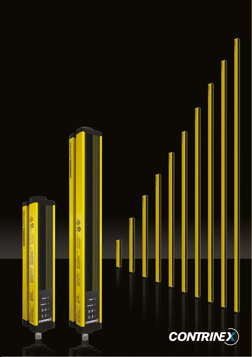
1.2. Safetinex safety systems .........................................................................5
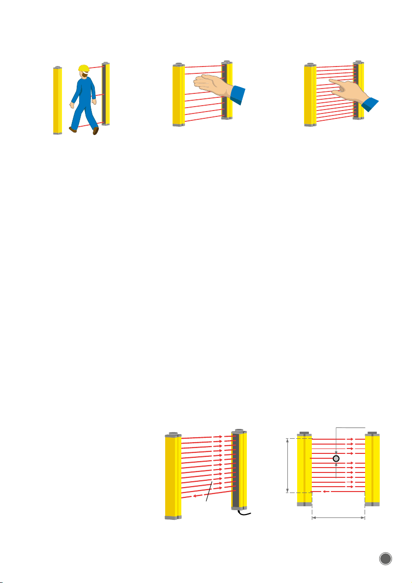
1.3. Active optoelectronic protective devices (AOPD) ................................... 5
1.3.1. Safeguarding function ........................................................................6
1.3.2. Hazardous area ..................................................................................6
1.3.3. AOPD detection capability .................................................................6
1.4. Advantages of AOPDs.............................................................................7
1.5. Operating principle..................................................................................7
1.6. Certification of Safetinex products........................................................... 8
2. EUROPEAN SAFETY STANDARDS ..............................8
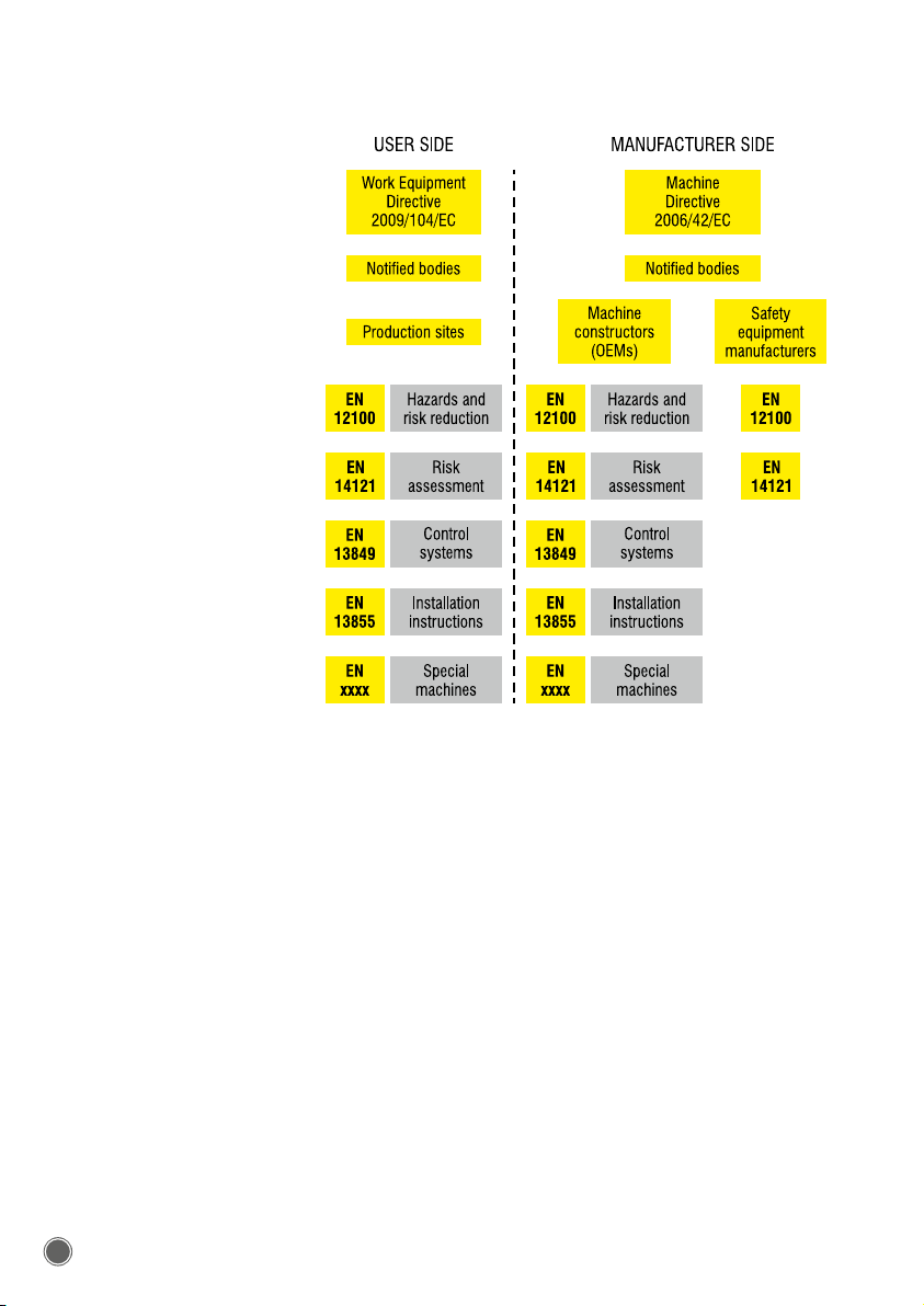
2.1. Types of safety standards applicable in the EU ...................................... 8
2.2. Examples of safety standards..................................................................9
2.3. An approach to European standards ...................................................... 9
2.4. The user side .........................................................................................10
2.5. Machine manufacturer side ...................................................................10
2.6. Notified bodies.......................................................................................11
3. NORTH AMERICAN SAFETY STANDARDS ..............11
3.1. A different approach .............................................................................. 11
3.2. OSHA Regulations and U.S. Consensus Standards .............................12
3.3. North American Standards for safety issues: UL, ANSI and CSA.........13
3.3.1. American standard agencies ........................................................... 13
3.3.2. Canadian standard agencies ...........................................................13
3.4. International standard agencies ............................................................14
4. RISK ASSESSMENT......................................................14
4.1. Definition of hazards and risk reduction strategy .................................. 14
4.2. Risk assessment process ...................................................................... 14
4.3. Methods for determination of risk level.................................................. 17
4.3.1. Determination of risk level in North America ....................................17
4.3.2. Determination of required performance level (PLr)..........................17
4.3.3. Specific standards for safety distance calculation...........................19
5. INSTALLATION ............................................................19
5.1. Installation rules ..................................................................................... 19
5.1.1. Positioning the AOPD .......................................................................19
5.1.2. Minimum safety distance required ...................................................20
5.1.3. Minimum safety distance calculation (EU) ....................................... 21
5.1.4. Minimum safety distance calculation (US & Canada)......................23
6. OTHER COUNTRIES ....................................................24
7. ACRONYMS..................................................................25
8. TECHNICAL DOCUMENTATION ...............................26
8.1. Safetinex YBB for finger protection........................................................26
8.2. Safetinex YBB for hand protection.........................................................26
8.3. Safetinex YCA for access control .......................................................... 26

Contrinex Industrial Electronics Contrinex Industrial Electronics 5
4
8.4. Advantages of the Safetinex range .......................................................27
8.5. Scope of this technical documentation ................................................. 27
8.6. Self protected outputs............................................................................27
8.7. Resolution (R) of an AOPD ....................................................................28
8.8. LED status indicators.............................................................................29
8.9. Configurable functions........................................................................... 29
8.9.1. Transmission channel selection (YBB and YCA).............................. 29
8.9.2. Test Mode selection (YBB) ...............................................................30
8.9.3. Operating range selection (YCA) ..................................................... 30
8.10. Installation..............................................................................................30
8.10.1. Minimum safety distance..................................................................30
8.10.2. Recommended beam heights for access control devices (YCA) .... 31
8.10.3. Positioning the sender and receiver units ........................................ 31
8.10.4. Distance from reflective surfaces ..................................................... 32
8.10.5. Installation of multiple systems.........................................................33
8.10.6. Mechanical installation .....................................................................34
8.11. Connecting the protective device..........................................................36
8.11.1. Power supply ....................................................................................36
8.11.2. Electromagnetic compatibility (EMC) ............................................... 36
8.11.3. Light radiation................................................................................... 36
8.11.4. Pin assignment ................................................................................. 37
8.12. Safetinex safety relay YRB-4EML-31S ...................................................38
8.12.1. Response time from protective field intrusion
to switching of safety relay ...............................................................38
8.12.2. Connection examples for YRB-4EML-31S safety relay ....................39
8.13. Alignment of sender and receiver units.................................................40
8.14. Test before the first commissioning .......................................................41
9. TESTING AND MAINTENANCE .................................42
9.1. Daily functional test................................................................................ 42
9.1.1. Finger and hand protection devices (YBB models) .........................42
9.1.2. Access control devices (YCA models)............................................. 43
9.2. Troubleshooting .....................................................................................44
9.3. Preventive periodic inspections.............................................................45
9.4. Cleaning.................................................................................................45
9.5. Daily testing log file................................................................................ 45
10. AVAILABLE MODELS ..................................................47
11. DISCLAIMER ................................................................51
12. EC DECLARATION OF CONFORMITY .......................53

Contrinex Industrial Electronics Contrinex Industrial Electronics 5
4
1. INTRODUCTION
1.1. CONTRINEX
Contrinex, a multinational company with headquarters in Switzerland,
is specialized in the development, production and worldwide sales of
position sensors, RFID and safety systems. Contrinex employs over
500 people, including 25 highly qualified R&D engineers, operates
production units in Switzerland, China, USA, Sri Lanka and Brazil, has
its own sales offices in all the major markets and is represented in over
60 countries. Contrinex applies stringent management and production
principles, which are reflected in its ISO 14001:2004 and ISO 9001:2008
certifications. Additionally, Contrinex is subject to regular client-based
audits. Identical quality controls and equipment as well as staff recruit-
ment and training policies are implemented at the different production
sites, thus guaranteeing consistent product quality.
1.2. SAFETINEX SAFETY SYSTEMS
The Safetinex product lines produced by Contrinex offer high quality
safeguarding solutions for both personnel and machinery. Our specialists
in sensor technology have developed high-performance electro-sensitive
protective equipment. Our range of safety products comprises highly
sensitive devices for finger and hand protection as well as access control,
featuring various lengths and connection options.
Safetinex products have been developed in compliance with the appli-
cable international safety standards and have obtained the required
product certification for use in the European Union, the United States
of America and all other countries where the applicable IEC standards
have been adopted.
1.3. ACTIVE OPTOELECTRONIC PROTECTIVE
DEVICES (AOPD)
When looking to build a safety system around a danger zone, the first
consideration is whether or not optical protection is suitable at all. For
this to be the case, it must be possible for the machine control to be
electrically influenced by means of the AOPD’s semiconductor output.
Moreover, it must also be possible to instantly terminate or exit the
hazardous process in every operating phase. Further, there must be no
danger of injury due to heat, radiation or from materials or components
ejected by the machine. If such danger exists, then either the optical
system is not suitable, or the danger must be otherwise excluded by
applying additional safety measures.
The selection of a specific type of safeguard involves an evaluation of
the hazard, in order to determine the applicable category or required
performance level PLr.

Contrinex Industrial Electronics Contrinex Industrial Electronics 7
6
The choice of an active optoelectronic protective device (AOPD), such
as a safety light curtain, depends on:
–The relevant safety standards to be applied
–The definition of the safeguarding function
–The available space around the hazardous area
–The safety distance, as calculated by the appropriate formula and
depending on the AOPD’s resolution and position, as well as the
response times of the light curtain or access control barrier, the safety
relay and the machine stopping time
–Ergonomic factors (e.g. how often access is necessary)
–Commercial criteria
1.3.1. SAFEGUARDING FUNCTION
The AOPD resolution must be chosen according to the application and
the required safeguarding function. It is defined as the minimum size of
an object that can be reliably and safely detected at any position in the
protective field. Basically, two approaches can be considered:
–Point of operation: detection of fingers or hands entering the defined
hazardous area. The protective equipment immediately stops the
machine or renders it harmless. The Safetinex YBB range is best
suited for this type of application.
–
Perimeter or entry-exit: once the entry of a person has been detected,
the hazardous motion of the machine is stopped. The control device
enabling the operator to restart the machine must be located outside
the hazardous area. From there, the operator must have a full view
of the hazardous area to verify that nobody is in it before restarting
the machine. The Safetinex YCA range is best suited for this type
of application.
In both cases, the primary function of the protective device is to stop the
machine before the hazardous point is reached and to prevent uninten-
tional machine start-up or restart. This function must comply with the
category or performance level of the safety-related components of the
machine’s control system.
1.3.2. HAZARDOUS AREA
The hazardous area can be defined in terms of:
–The dimensions of the zone that requires protection
–The different access points to accessible hazards
–The risk of an undetected presence in the hazardous zone, or risk of
bypassing the protective device
1.3.3. AOPD DETECTION CAPABILITY
The light curtain or barrier detection capability (or resolution) depends
on the distance between the centerlines of each beam emitted by the
sender. The choice for a specific resolution depends on the part of the
body which needs protection (finger, hand, whole body).

Contrinex Industrial Electronics Contrinex Industrial Electronics 7
6
1.4. ADVANTAGES OF AOPDS
Safeguarding devices are used where risks cannot be eliminated by
machine design. Rather than preventing access to a hazardous area,
safety light curtains or access control barriers detect the entry of a person
or part of a body and eliminate the hazard by triggering an immediate
stop of the hazardous machine motion. They present several advantages
over mechanical safeguarding devices:
–
Access time to the machine is reduced, thereby increasing productivity
–
Workplace ergonomics are greatly improved and less space is required
–The invisible infrared beams allow better visibility of the machine and
operating process
–Protection applies to any approaching person
1.5. OPERATING PRINCIPLE
A light curtain or access control barrier comprises two units, namely a beam
sender (or transmitter) and a receiver between which coded infrared beams
are sequentially exchanged. The protective field is the area enclosed by
these two components, the emitted light beams forming a permanent,
though invisible, shield between the two units. The receiver unit is connected
to a safety relay which transmits the signal to the machine control unit.
Synchronization between the sender and receiver devices is performed
optically, i.e. wired connection between the two units is not necessary.
FIG. 1: RESOLUTION OF THE ACCESS CONTROL BARRIER OR LIGHT CURTAIN
Beam resolution 30 mmBeam separation > 30 mm Beam resolution 14 mm
FIG. 2: OPERATING PRINCIPLE
Sender Receiver
Protective field
Resolution (R)
Protective height
Operating distance (d)

Contrinex Industrial Electronics Contrinex Industrial Electronics 9
8
When properly installed, the protective device detects any relevant entry
into the hazardous area. As soon as such an entry is detected, the pro-
tective device immediately triggers the safety relay, which in turn causes
the machine control system to bring the machine to a safe status and/
or complete stop, thus eliminating the hazard.
The size of the protective field depends on the dimension of the AOPD
and the distance between the sender and receiver units.
AOPDs are also commonly used as sensors to automate industrial
operations where no critical human safety issue is involved. However,
when directly linked to the safety of persons, their design and installation
are strictly regulated.
1.6. CERTIFICATION OF SAFETINEX PRODUCTS
Safetinex YBB/YCA products satisfy all the requirements of category 4,
PL e, according to EN/ISO 13849-1 (formerly EN 954-1) Type 4 accord-
ing to EN/IEC 61496-1 and -2 and SIL 3 according to EN/IEC 61508.
Before considering the use of Safetinex products in machine safety
applications, it must be verified that the product certifications are valid
in the country where the product is to be used.
The following chapters provide a brief introduction to the main standards
and regulations applicable in the European Community and in North
America. They are by no means a complete guide and only serve as a
reminder of the most important issues. For detailed information, please
refer to the original documents.
2. EUROPEAN SAFETY STANDARDS
This section is intended to provide help for designers and users of indus-
trial machinery. It summarizes the basic principles of European directives,
procedures and regulations in terms of protection against hazards in the
work environment. It is by no means a complete guide and only serves
as a reminder of the most important issues. For detailed information,
please refer to the original documents.
2.1. TYPES OF SAFETY STANDARDS
APPLICABLE IN THE EU
In the European Union, safety is legislated. The EU’s Machinery Direc-
tive requires that all machines and safeguarding devices operating in
EU countries meet essential safety standards. Harmonized European
standards regarding machine safety policies are prepared by the CEN
(European Committee for Standardization) or CENELEC (European
Committee for Electrotechnical Standardization) and finalized by the EU
Commission. Once ratified, these standards become European Standards
(EN) that take precedence over national laws. Thus, EU countries must
remove or modify any national standard that conflicts with the European
Standard. CENELEC and CEN cooperate closely with ISO and IEC, the
main bodies for international standards.

Contrinex Industrial Electronics Contrinex Industrial Electronics 9
8
Applicable standards usually have the prefix EN (“European Norm”), but
most also have international – ISO/IEC – equivalents. There are different
types of standards:
–
A-type standards are basic safety standards applicable to all machin-
ery, e.g. EN/ISO 14121
–B1-type standards set out special safety aspects and procedures,
e.g. EN/ISO 13849-1
–B2-type standards set rules on safety equipment design, e.g. EN/
IEC 61496-1, EN/TS/IEC 61496-2/-3
–C-type standards set safety requirements for a specific machine or
type of machine
2.2. EXAMPLES OF SAFETY STANDARDS
In addition to the Machinery Directive 2006/42/EC and the Work Equip-
ment Directive 2009/104/EC, there are standards that specifically focus
on protective equipment, such as:
TYPE SCOPE EUROPEAN
STANDARDS
INTERNATIONAL
STANDARDS
ASafety of machinery
Basic principles
EN 12100-1
EN 12100-2
ISO 12100-1
ISO 12100-2
Risk assessment EN 14121-1
EN 14121-2
ISO 14121-1
ISO 14121-2
BInterlocking devices EN 1088 ISO 14119
Guards EN 953
Safety related parts of
control systems
EN 13849-1
EN 13849-2
ISO 13849-1
ISO 13849-2
Safety of machines:
Electro-sensitive
protective equipment
EN 61496-1
EN 61496-2
EN 61496-3
IEC 61496-1
IEC 61496-2
IEC 61496-3
Safety distance details EN 13855 ISO 13855
Positioning of protective
equipment
EN 13855 ISO 13855
TABLE 1: EXAMPLES OF SOME APPLICABLE SAFETY STANDARDS
For additional information regarding European standards, please refer to
www.din.de, www.iec.ch, www.iso.org.
2.3. AN APPROACH TO EUROPEAN STANDARDS
The European Union has chosen to regulate the production, installation
and use of old, modified and new machines within the European Union
territory by approaching the parties concerned separately, i.e. one legal
framework has been created for users and another for manufacturers.
The Work Equipment Directive sets out the rules applying to users of
machines on production sites, while the Machinery Directive sets out
those applying to machine constructors and safety equipment manu-
facturers. However, most subordinate standards apply to both parties,
as shown in the following chart.

Contrinex Industrial Electronics Contrinex Industrial Electronics 11
10
2.4. THE USER SIDE
The user side is regulated by the Work Equipment Directive, which
states that users of a machine are obliged to make sure that it complies
with the legal requirements. Hence, if the user buys a machine which
does not comply with the EU Machinery Directive, it is his responsibility
to take the necessary actions to bring the machine up to the required
quality and safety level.
Additionally, the Work Equipment Directive specifies what minimum
regulations must be observed for safety purposes when work equipment
is being used. The original text can be found on the relevant European
Union website.
2.5. MACHINE MANUFACTURER SIDE
The manufacturer side is addressed by the Machinery Directive. This
umbrella document refers to the specific requirements described in EN
standards, and stipulates that each danger zone of a machine must be
made safe. The method used to make different zones safe depends on
the type of hazard.
The Machinery Directive requires that, before placing machinery on
the market and/or putting it into service, the manufacturer ensures that
TABLE 2: EUROPEAN MACHINE SAFETY OVERVIEW – USER AND MANUFACTURER SIDE.

Contrinex Industrial Electronics Contrinex Industrial Electronics 11
10
a technical file is made available. This technical file shall comprise a
construction file including, among others: “the documentation on risk
assessment demonstrating the procedure followed, including:
(i) a list of the essential health and safety requirements which apply to
the machinery,
(ii) the description of the protective measures implemented to eliminate
identified hazards or to reduce risks and, when appropriate, the indica-
tion of the residual risks associated with the machinery.” (Machinery
Directive 2006/42/EC, Annex VII, A, 1, a)
Machines that are highly hazardous (as listed in Annex IV of the Machin
-
ery Directive) must conform to special procedures. The manufacturer is
responsible for obtaining conformity through various procedures that may
require examination of the machine by an EU notified body.
2.6. NOTIFIED BODIES
In order to have control over the execution of these directives, verification
of certain steps by certifying bodies may be imposed by the directives. For
example, all safety device concepts must be analyzed, checked and tested
by such a third party organization. In many cases, this third party organiza-
tion also audits the production process of a safety device manufacturer.
A notified (or certified) body is a certification, inspection or testing body
designated by the notifying authority of an EU member state to issue
attestations of conformity for products. Each EU member state has a list of
notified bodies authorized to issue EU-type examination certificates. The
lists include the identification number of each notified body, as well as the
specific areas of activity and the tasks for which it has been designated.
European notified bodies responsible for carrying out conformity assess-
ment procedures can be found through the NANDO (New Approach
Notified and Designated Organizations) website, where accredited bodies
can be searched for by country, product or directive. An official list of
notified bodies responsible for assessing products in compliance with
the Machinery Directive can also be found on the relevant European
Union website.
3. NORTH AMERICAN SAFETY STANDARDS
This section is intended to provide help for designers and users of indus-
trial machinery. It summarizes the basic principles of North American
regulations and standards in terms of protection against hazards in the
working environment. It is by no means a complete guide and only serves
as a reminder of the important issues. For detailed information, please
refer to appropriate agencies and documents.
3.1. A DIFFERENT APPROACH
Whereas European standards are mainly machine manufacturer oriented,
North American standards are primarily directed towards users. Unlike
in the EU, third party certification is not mandatory in the US or Canada.
In terms of liability, it is the employer’s responsibility to prove that he has

Contrinex Industrial Electronics Contrinex Industrial Electronics 13
12
done his utmost to ensure his employees’ safety. However, certification
has become a strong commercial asset in terms of market requirement.
On users’ request, national compliance agencies assess and grant the
required certification.
Although the US and the EU have different methods for developing
and applying standards, their purpose is the same, namely to ensure
an appropriate level of safety in the workplace. Harmonized standards
have the advantage of promoting world trade and reducing duplication of
effort. Harmonized international standards allow manufacturers to access
many markets with one product. Users profit from competitive products
that meet uniform quality and functional requirements – wherever the
y
were manufactured.
In the United States, standards are developed and enforced both by
governmental agencies and industry groups. US employers, installers or
OEMs are legally responsible for compliance with all applicable regula-
tions, both national and international. In the US, the Occupational Safety
and Health Administration (OSHA) is a federal agency that can enforce
its regulations through penalties and fines.
3.2. OSHA REGULATIONS AND U.S. CONSENSUS
STANDARDS
The Occupational Safety and Health Act passed on Dec. 29, 1970 estab-
lished guidelines for safe and healthy working conditions.
Occupational Safety and Health Standards in the U.S. are defined in
Title 29 of the Code of Federal Regulations Part 1910. Subpart O of this
document deals specifically with machinery and machine guarding, and
defines the general requirements for all machines (1910.212) and for
some specific types of machinery.
Encouraged and assisted by OSHA, more than half of the US states
have developed their own safety and health programs and regulations
which are then enforced by OSHA as “National Consensus Standards”.
Information on both state plans and OSHA regulations may be obtained
from their respective websites.
OSHA uses national consensus standards to further define machine pro-
tection requirements in addition to subpart O. In 1910.212, it states: “The
point of operation of machines whose operation exposes an employee
to injury, shall be guarded. The guarding device shall be in conformity
with any appropriate standards therefore, or, in the absence of applicable
specific standards, shall be so designed and constructed as to prevent
the operator from having any part of his body in the danger zone during
the operating cycle.”
“Any appropriate standards” refers to national consensus standards gen-
erally recognized in the industry. Bodies frequently referenced by OSHA
include the American National Standards Institute (ANSI), the National
Fire Protection Agency (NFPA), Underwriters Laboratories (UL) and the
American Society of Mechanical Engineers (ASME).
As an example, ANSI B11.1 sets safety requirements for mechani-
cal power presses, ANSI B11.15 specifies standards for pipe bending
FIG. 3: APPLICATION EXAMPLES
OF YCA AND YBB DEVICES
YCA
YBB

Contrinex Industrial Electronics Contrinex Industrial Electronics 13
12
machines, ANSI B11 TR.1 gives ergonomic guidelines for the design,
installation and use of machine tools, and ANSI/RIA R15.06 stipulates
the safety requirements for industrial robots. Please consult national
consensus standards bodies for complete listings.
3.3. NORTH AMERICAN STANDARDS FOR
SAFETY ISSUES: UL, ANSI AND CSA
3.3.1. AMERICAN STANDARD AGENCIES
UL STANDARDS
Underwriters Laboratories Inc. is a testing organization established in
1894 and is authorized to conduct certification testing of any electrical
device. Although UL certification is not mandatory, many companies
strive to obtain its certification for products aimed at the U.S. market.
UL certification has two levels, namely listing certification, generally for
final products, and recognition certification, for parts or components built
into a product. Once a product has obtained UL certification, additional
on-site inspections are carried out on a quarterly basis to ensure that
the production plant continues to manufacture products conforming to
UL standards.
Since the purpose of UL standards is to eliminate the danger of fire or
electric shock caused by electrical appliances, in principle only those
appliances presenting such risks are subject to this certification.
For more details on the UL Standards, please consult the UL website.
ANSI STANDARDS
The American National Standards Institute was founded in 1918 to
manage the standardization system in the US. It is not ANSI’s task to
create standards of its own, but rather to approve the standards set up
by specialized organizations. Many UL standards have been converted
into ANSI/UL standards.
For instance, ANSI standards include ANSI B 11.19: Standard for per-
formance of safeguarding devices and ANSI/RIA R15.06: Standard for
robot safety.
For more details on the ANSI Standards, please visit the ANSI website.
3.3.2. CANADIAN STANDARD AGENCIES
CSA STANDARDS
The Canadian Standards Association is an organization that administers
and coordinates the standardization system in Canada. Cross-certification
between the U.S. and Canada has been granted, based on the Mutual
Recognition Agreement (MRA).
Electrical appliances connected to a public power source in Canada
must conform to CSA Standards. Manufacturers of these products need
to obtain C-UL or CSA certification, or the seller needs to apply for cer-
tification directly to the provincial authorities.
For more details on the CSA Standards, please visit the CSA website.

Contrinex Industrial Electronics Contrinex Industrial Electronics 15
14
3.4. INTERNATIONAL STANDARD AGENCIES
International standards also play a significant role in North American
machine safety. The two main international entities are the Interna-
tional Electrotechnical Committee (IEC) and the International Standards
Organization (ISO). IEC is a recognized provider of standards in the
electrotechnical field and is composed of national electrotechnical com-
mittees. ISO is an international federation of national standardization
bodies. ISO and IEC influence international standards through formal
relationships. In the US, ANSI coordinates with ISO and IEC through
technical advisory groups (TAG).
4. RISK ASSESSMENT
4.1. DEFINITION OF HAZARDS AND RISK
REDUCTION STRATEGY
EN/ISO 12100 serves as a basis for all subsequent standards. It describes
every type of hazard that needs to be considered in terms of machine
safety. Exposure to hazards includes numerous potential situations that
must first be identified.
Mechanical hazards may result in crushing, shearing, cutting/severing,
entanglement, drawing-in/trapping, impact, stabbing/puncture, friction/
abrasion, injuries due to high pressure fluid ejection, etc. Machine hazards
are also influenced by sharp edges, vibrations and unstable or moving
objects. The list quotes electrical and thermal hazards, radiation, dust
and hazardous substances (gas, vapors). In terms of ergonomics and
the working environment, there are risks of falling, tripping or slipping. A
combination of hazards may result in a specific new hazard.
EN/ISO 12100 subsequently gives general guidelines for eliminating or
reducing hazards through prevention and protection. It is recommended to
use technology that avoids most of the problems linked with the hazards
listed above. Any decision that contributes to prevention against hazards
is part of the security process and risk reduction strategy.
In this respect, taking ergonomic principles into consideration is important.
A high level of automation will not only help operators, it will also increase
productivity and reliability. Reducing unnecessary human movements and
efforts can contribute to a safer working environment. Proper lighting of
the work place will help to minimize hazards.
Operators must be able to stop machines at any time in case of an emer-
gency. Starting and/or restarting the machine after an interruption must
be carefully planned. When programmable electronic safety systems are
used, the behavior of such systems in case of defect and the protection
of the software requires particular attention.
4.2. RISK ASSESSMENT PROCESS
In essence, conducting a risk assessment involves identifying hazards,
evaluating the potential severity of harm and identifying measures and
solutions for eliminating or reducing such risks.
EN/ISO 12100

Contrinex Industrial Electronics Contrinex Industrial Electronics 15
14
This requirement is stated in U.S. standards (Title 29 US Code of Federal
Regulations, Part 1910, Subpart O).
For more details, please refer to the following documents:
–OSHA 3071, Job Hazard Analysis
–ANSI/RIA R15.06-1999, Safety Requirements for Industrial Robots
and Robot Systems
–ANSI B11.TR3, Risk Assessment and Risk Reduction
–EN/ISO 14121, Principles of Risk Assessment. EN/ISO 14121 refers
to additional standards, such as EN/ISO 13849-1 and EN/ISO 12100.
The following chart, based on EN/ISO 12100-1 and ANSI B11.TR3:2000,
can be used to carry out risk analyses and ensure that all issues have
been thoroughly considered. This iterative process must be carried out for
every machine operating in the work place, as well as for all the potential
hazards associated with each machine.
PROCESS STARTS
PROCESS ENDS
no
no
no
no
no
yes
yes
yes
yes
yes
no
yes
no
no
no
yes
yes
yes
no
yes
no
yes
Determine
machine limits
Identify hazards
Estimate and evaluate
the level of risk
Can the hazard
be eliminated?
Have additional
hazards been
added?
Has risk
been adequately
reduced?
Perform risk reduction
through design changes
Document risk
assessment
Perform risk reduction
through machine
safeguarding
Perform risk reduction
through personal
protective devices
Perform risk reduction
through training
or awareness
Can the hazard be
reduced through
design changes?
Can the hazard be
reduced through machine
safeguarding?
Can the hazard be
reduced through personal
protective devices?
Can machine
limits be
respecified?
Has risk
been adequately
reduced?
Has risk
been adequately
reduced?
Has risk
been adequately
reduced?
Has risk
been adequately
reduced?
DIAGRAM 1: RISK ASSESSMENT PROCESS

Contrinex Industrial Electronics Contrinex Industrial Electronics 17
16
This risk analysis and assessment process helps to take all the different
aspects of potential machine hazards into consideration. It is important to
document this procedure as evidence that the task has been fully carried
out and to allow others to check it or use it for further improvements.
EN/ISO 14121 also describes procedures for identifying hazards and
assessing risks, and provides guidance on the information required to
achieve this goal. The process involves analyzing the risks in a systematic
and documented way, in order to eliminate or reduce hazards. Qualitative
and quantitative methods can be used.
All aspects of potential hazards must be taken into consideration:
–The phases of a machine’s life
–The full range of foreseeable uses and misuses of a machine
–All persons possibly exposed to hazards when the machine is being
used
Risk is defined as a function of the severity of possible harm and the
probability that such harm occurs (frequency and duration of exposure,
possibility of avoiding harm, etc.). One important piece of information is
the history of accidents, if available.
Among the aspects to be considered when establishing elements of risk,
the analysis should account for
–Different types of exposure depending on the type of work (setting,
teaching, operating, cleaning, etc.)
–Human factors, such as applicability and ergonomic issues
–The reliability of safety functions, including their maintenance
–The possibility to defeat or circumvent safety measures
EN/ISO 14121-1:2007 gives a full list of hazards referenced by EN/
ISO 12100.
In addition, the safety of any machine will diminish with time due to the
deterioration of components, wear, loosening of parts, etc. It is therefore
important to conduct regular inspections in order to detect defects that
may lead to reduced safety, and to effect the necessary repairs before
the level of risk exceeds the original assessment.
EN/ISO 14121

Contrinex Industrial Electronics Contrinex Industrial Electronics 17
16
4.3. METHODS FOR DETERMINATION OF RISK
LEVEL
The methods used for assessing the risks associated with a specific
machine are addressed by several standards. Standards either impose
or recommend corrective measures that will establish an adequate level
of safety.
4.3.1. DETERMINATION OF RISK LEVEL IN NORTH AMERICA
In order to select the appropriate safety device adapted to the actual
risks and dangers, it is important to assess the risk. ANSI B11.TR3-2000
provides a “Risk Estimation Matrix” in order to determine the level of risk
depending on the cross-referenced factors of the probability of harm
occurrence and harm severity:
PROBABILITY
OF HARM
OCCURRENCE
SEVERITY OF HARM
CATASTROPHIC SERIOUS MODERATE MINOR
Very Likely High High High Medium
Likely High High Medium Low
Unlikely Medium Medium Low Negligible
Remote Low Low Negligible Negligible
TABLE 3: RISK ESTIMATION MATRIX AS PRESENTED BY ANSI B11.TR3-2000
The purpose of assessing the risk is to determine the appropriate level
of safety. It is important that the protective device complies with the
determined risk and is adapted to the machine control system. Risk
assessment applies to each element that makes up the safety system,
and not just the protective device itself. In particular, safety devices can
only be used on machines that comply with control reliability as described
in OSHA 29.1910.212 and ANSI B11.19-20.
Another important point to be considered is the life cycle of the machine
and its protective devices. The safety of any machine will diminish with
time due to the deterioration of components, wear, loosening of parts,
etc. It is therefore important to conduct regular inspections in order to
detect defects that may lead to reduced safety, and to effect the neces-
sary repairs before the level of risk exceeds the original assessment.
4.3.2. DETERMINATION OF REQUIRED PERFORMANCE
LEVEL (PLr)
EN/ISO 13849-1 sets out a procedure for the selection and design of
safety measures. The procedure contains the following 6 steps:
1. Identify the safety functions to be performed
2. Determine the required performance level
3. Design and technical realization of the safety functions
4. Evaluate the achieved performance level
5. Verify the achieved performance level
6. Validate that all requirements are met
EN/ISO 13849

Contrinex Industrial Electronics Contrinex Industrial Electronics 19
18
Based on risk identification, the required performance level of risk
reduction is determined using the following graph sourced from EN/
ISO 13849-1, Annex A.
The objective is to determine the required performance level PLr that
sets the requirements of the necessary safety system, depending on the
risks involved in each case. As described below, three parameters are
taken into consideration:
1. The potential severity of the harm
2. The frequency and/or duration of exposure to the hazard
3. The possibility of avoiding the hazard
In order to reduce the determined risk (PLr) to an appropriate level, a
safety system with performance level PL ≥PLr needs to be properly
implemented. A corresponding average probability of dangerous failure
per hour (PFHD) can be associated with each performance level:
DIAGRAM 2: REQUIRED PERFORMANCE LEVEL
PLr
L
H
P2
F2
S2
P1
P2
F1
P1
P2
F2
S1
1
P1
F1
P2
P1 a
b
c
d
e
1 Starting point for evaluation of safety function contribution to risk reduction
S Severity of injury:
S1 Slight (normally reversible injury)
S2 Serious (normally irreversible injury or death)
F Frequency and/or exposure to hazard:
F1 Seldom-to-less-often and/or exposure time is short
F2 Frequent-to-continuous and/or exposure time is long
P Possibility of avoiding hazard or limiting harm:
P1 Possible under specific conditions
P2 Scarcely possible
PLr Required performance level
Low contribution
to risk reduction
High contribution
to risk reduction

Contrinex Industrial Electronics Contrinex Industrial Electronics 19
18
PERFORMANCE LEVEL (PL) AVERAGE PROBABILITY OF DANGEROUS FAILURE PER HOUR
a 10-5 ≤PFHD< 10-4
b 3 x 10⁻⁶ ≤PFHD< 10-5
c 10-6 ≤PFHD< 3 x 10⁻⁶
d 10-7 ≤PFHD< 10-6
e 10-8 ≤PFHD< 10-7
TABLE 4: AVERAGE PROBABILITY OF DANGEROUS FAILURE PER HOUR
All Safetinex type 4 AOPDs fully comply to Performance Level e. For
details, please consult the product data sheet.
4.3.3. SPECIFIC STANDARDS FOR SAFETY DISTANCE
CALCULATION
EN/ISO 13855 gives details concerning the positioning of safeguards with
respect to the approach speeds of parts of the human body.
5. INSTALLATION
5.1. INSTALLATION RULES
All safety equipment has to be installed following the strict installation
instructions given by the manufacturer and the applicable standards.
Without proper installation, the safety device cannot fulfill its function
and will give a false impression of safety to persons approaching a
dangerous machine. EN/ISO 13855 defines the installation requirements
for safety light curtains and access control barriers with respect to the
approach speeds of parts of the human body. Below is a summary of
the key concepts.
5.1.1. POSITIONING THE AOPD
The level of safety depends on the way the device is positioned. The risk
assessment conclusions will help decide what position is best suited for
preventing foreseeable hazards. In order to ensure proper safeguard-
ing, special care must be taken to find the position that will not allow the
protective device to be bypassed and such that any hazardous machine
movement is safely stopped before potential harm occurs.
There are different classical ways to position safety light curtains:
–Vertically (perpendicular approach)
–Horizontally (parallel approach)
–In an L shape (combined perpendicular and parallel approach)
–Inclined (angular approach).
It must not be possible to pass over, below, around or go behind the
protective field. When positioning access control barriers, it must not
be possible to pass over the highest beam, below the lowest beam or
between two beams. If this cannot be guaranteed, then additional protec-
tive devices must be used.
EN / ISO 13855
EN/ISO 13855

Contrinex Industrial Electronics Contrinex Industrial Electronics 21
20
For practical details on L-shaped installations, please consult the relevant
paragraph on page 34.
5.1.2. MINIMUM SAFETY DISTANCE REQUIRED
Since the principle of light curtains and access control barriers is to detect
an intrusion early enough to intervene in the machine cycle before anyone
has had time to reach the danger zone, positioning of protective equip-
ment must respect the approach speed of parts of the human body, as
well as the total response time of the installed safety system.
The following methodology, based on EN/ISO 13855, can be used to
determine the proper minimum safety distance:
FIG. 4: POSITIONING THE LIGHT CURTAIN
SAFE
SAFE
Other manuals for YBB Series
1
This manual suits for next models
33
Table of contents
Popular Safety Equipment manuals by other brands

KStrong
KStrong AFA940014 User instruction manual

e-breathe
e-breathe Multimask M Assembly and Fitting Instructions

Stearns
Stearns 33M42-B06 owner's manual

AES Corporation
AES Corporation 7740 Installation and operation manual

Singing rock
Singing rock EvaQ HUB II Instructions for use

SSP
SSP HOLDX RL2 operating manual