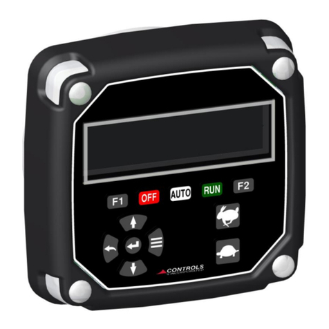
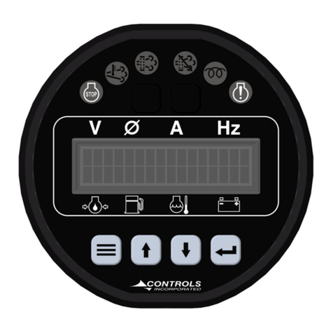
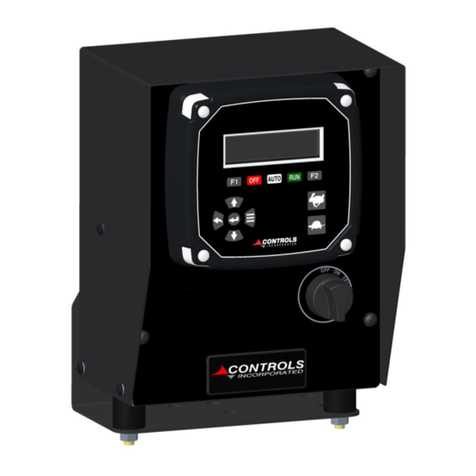
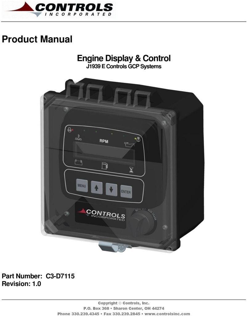
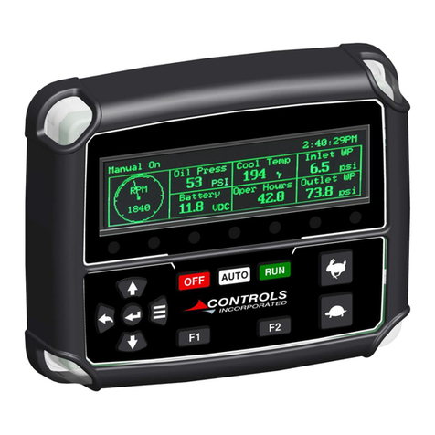
Controls MVP-A6235 User manual

Product Manual
Engine Control Module
Kubota Diesel Engines
Part Number: MVP-A6235
Revision: 2.0
Engine Type: Kubota Diesel with DPF Emissions Control
______________________________________________________________________________________________________________________________________
Copyright Controls, Inc.
P.O. Box 368 • Sharon Center, OH 44274
Phone 330.239.4345 • Fax 330.239.2845 • www.controlsinc.com

CONTROLS, INCORPORATED
C O N T R O L S Y S T E M S & S O L U T I O N S
- 1 -
TABLE OF CONTENTS
INSTALLATION INFORMATION……...........………………………………...……………………………………………………………....2
CONNECTOR INFORMATION……...........………………………………...………………..………………………………………………….3
MENU NAVIGATION………………………………………………………………..……………………………………………..…………….…......5
MENU SYSTEM…………………………………………………………………...…………………………………………………..……………….…......6
OPERATOR MENU…………………………………………………………………..…………………………………………………..………….…......8
EMISSIONS PARAMETERS
ACTIVE FAULT CODES
STORED FAULT CODES
OPERATION EVENT LOG
ALARM EVENT LOG
ENGINE PARAMETERS
ENGINE IDENTIFICATION
MODULE INFORMATION
CONTROLER SETUP MENU……………………………………………………………………………………………….….…………...……..11
QUICK SETUP
PARAMETER CONFIGURATION
INPUT CONFIGURATION
THROTTLE CONFIGURATION
ENGINE SAFETY CONFIGURATION
MODULE CONFIGURATION
DISPLAY CONFIGURATION
MAINTENANCE CONFIGURATION
PANEL ENGINE SAFETY PROTECTION …………………………………….……………………………………......……..……..…17
PRE ALARMS AND ALARMS
SAFETY SHUTDOWNS
INDICATOR LAMPS
EMISSIONS MONITORING - REGENERATION……………………….……………………………………....……....……..…18
REGEN LEVELS
REGEN BUTTONS
PARKED REGENERATION PROCESS
REGEN STATUS
REGEN FAIL/ABORT

CONTROLS, INCORPORATED
C O N T R O L S Y S T E M S & S O L U T I O N S
- 2 -
INSTALLATION INFORMATION

CONTROLS, INCORPORATED
C O N T R O L S Y S T E M S & S O L U T I O N S
- 3 -
CONNECTOR INFORMATION
BATTERY +
CAN HIGH
CAN LOW
DIGITAL INPUT 1
FUEL LEVEL
BATTERY -
5VDC SUPPLY
NEUTRAL SWITCH
THROTTLE DOWN
THROTTLE UP
PARKING BRAKE SW
GROUND (B-)
1
2
3
4
5
6
1
2
3
4
5
6
Part# 3FK-108
Connector A Kit
(1) Deutsch DT06-6S plug
with (6) 0462-209-10614 sockets

CONTROLS, INCORPORATED
C O N T R O L S Y S T E M S & S O L U T I O N S
- 4 -
PANEL CONNECTOR
Engine Harness Connector –Deutsch 21 pin (HDP24-24-21PE)
21 Pin Connector
Pin
Function
B
Battery Positive
E
Battery Negative
G
Key On Power
D
Crank Signal
V
J1939 High
U
J1939 Low
J
Alternator Excite
P
Neutral Switch Input
A
Parking Switch Input
Engine Harness
Connector (21 Pin)

CONTROLS, INCORPORATED
C O N T R O L S Y S T E M S & S O L U T I O N S
- 5 -
MENU NAVIGATION
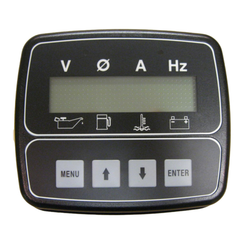
To access the control module menu system, power the unit and press the Menu button. While
pressing the menu button a message will appear to also press Enter to access.
Once you have accessed the menu system, the four key pad will be used for menu navigation and
therefore not available for engine speed control if the engine is running. The menu system is broken
into two main sections, the operator menu and the controller setup menu. The operator menu
contains information about the engine and control panel. The topics will vary based on the engine
type and control panel model. Pressing the Menu key will index the menu topic to the next item in
the list. The index is circular so you will eventually wrap around to the beginning of the operator
menu structure. Pressing the Enter key will index the topics backward. Once you have arrived at a
menu topic that you would like to explore more, press the Up arrow key. The Up arrow key will
index the screen each time it is pressed. Pressing the Down arrow key will index in the reverse order.
Pressing the Menu key at any time while in a topic will return you to the main menu topic heading.
To exit the menu, simply press the Menu and Enter keys simultaneously.
MENU SYSTEM
CONTROLS, INCORPORATED
C O N T R O L S Y S T E M S & S O L U T I O N S
- 6 -
OPERATOR MENU
First Menu
Operator
Menu
Controller
Setup
Menu

CONTROLS, INCORPORATED
C O N T R O L S Y S T E M S & S O L U T I O N S
- 7 -
Emissions Parameters
This menu allows for the viewing of the engine emissions data as broadcast by the ECU by pressing
the up arrow button. This data includes:
DOC Inlet Temperature
DPF Soot Load
DPF Inlet Temperature
Time at Last Regeneration
DPF Outlet Temperature
Active Regen Status
Regen Options
Regen Inhibit Status
DPF Differential Pressure
Active Fault Codes
This menu allows for the viewing of any Active Fault Codes as broadcast by the engine ECU by
pressing the up arrow button.
Stored Fault Codes
This menu allows for the viewing of any Stored Fault Codes as broadcast by the engine ECU by
pressing the up arrow button.
Operation Event Log
The operation log will record the engine start and stop events and tag them with the engine run
time hours. The Alarm can be viewed in the Operator menu area and can be cleared in the Module
Configuration section of the Controller Setup menu.
Alarm Event Log
Any monitored pre alarm or alarm will be recorded in the Operator menu section. The event will be
tagged with the actual engine run time hours at which the event occurred. The log stores the last 32
events and can be cleared in the Module Configuration section on the Controller Setup menu.
Engine Parameters
This menu allows for the viewing of unique engine information broadcast by the ECU by pressing
the up arrow buttons. This information includes:
Total Hours
Engine Torque
Requested TSC
Coolant Temperature
Rated Speed
Fuel Rate
Low Idle Speed
Manifold Temperature
Load at RPM
Potential Voltage
Engine Identification

CONTROLS, INCORPORATED
C O N T R O L S Y S T E M S & S O L U T I O N S
- 8 -
This menu allows for the viewing on the engine model number and serial number.
Module Information
This menu allows for the viewing of the Module Part number and Software Version.
Controller Setup
When navigating through the Operator menu, you will arrive at the Controller Setup screen. To
configure the module to new settings, you can enter into this area by pressing the Up arrow key.
The next screen will ask for a password. If no password, or an incorrect password is used, navigation
into the menu is still possible and permitted, however, the ability to make changes will be restricted.
To enter the password, press the Enter key and brackets will appear. Use the Up and Down arrow
keys to set each digit individually, pressing the Enter key to index to the next digit from left to right.
Once the last digit is entered, the brackets will disappear and the digits will be represented with
asterisks. Pressing the Up arrow will index you to the Quick Setup menu and programming can
continue.

CONTROLS, INCORPORATED
C O N T R O L S Y S T E M S & S O L U T I O N S
- 9 -
Navigating the Controller Setup menu structure is done in the same manner as the Operator menu
system. Menu will index to the next topic, The Up arrow will access the topic, etc. To make changes
to the settings, you will need to locate the item you are looking to modify under the appropriate
topic and then press the Enter key and the editing brackets will appear allowing you to make
changes to the value or change the selection. Once you have made your selection or changed the
value, simply press Enter again to accept it and the editing brackets will be removed.
CONTROLLER SETUP MENUS
QUICK SETUP
The Quick Setup menu is available to allow a user to quickly set up the basic configuration of the
control panel to match the engine. Selections in the Quick Setup will propagate into other areas of

CONTROLS, INCORPORATED
C O N T R O L S Y S T E M S & S O L U T I O N S
- 10 -
the control panel programming. For more detailed options, you can use the main menu structures
that follow.
Heading
Default
Range
Engine Manufacturer
Kubota (DPF)
Kubota (DPF)
TSC Min Speed
800
650-4000
TSC Max Speed
2900
650-4000
Performance Display
Off
On/Off
PARAMETER CONFIGURATION
The Parameter Configuration menu allows you to configure each critical engine parameter to the
source of the information. Sender type, scale and input channel to the module can be selected here.
You will first select the parameter, then the properties associated with each one.
Heading
Default
Range
Parameter
Fuel Level
Voltage
Hour meter
Fuel Level Sender
S-W
SW/VDO/0-90ohm
Fuel Channel
Plug A Pin 5
No Options
Voltage Source
Elect-J1939
Batt-J1939/Alt-J1939/Elect-J1939/Internal
Batt Volt Trim (100mV) (Internal Only)
0
Hour meter
Engine ECU
Internal/Engine ECU
Hour meter (Internal Only)
0 Hours
INPUT CONFIGURATION
The Input Configuration menu allows you to set up a discreet switch input that can be treated as Pre
Alarm or Alarm. Common text messages for power unit applications are preloaded. A custom
message can be assigned to the input.

CONTROLS, INCORPORATED
C O N T R O L S Y S T E M S & S O L U T I O N S
- 11 -
Heading
Default
Range
Configure
Channels
Channels/Custom Message
Digital Input
1
Normally
Open
Open/Closed
Action
Pre Alarm
Pre Alarm/Alarm/Throttle Up/Throttle Down/Neutral
Switch/Parking Brake/Hydro Throttle/Active Faults/Stored Faults
Message
Water in Fuel
See List
Check
Off
Off/Always/Run
Default Settings
1
Water in Fuel
4
Throttle Up
5
Throttle Down
Configure
Custom Message
Top Line Message
Alpha Numeric 14 Characters Max
Bottom Line
Message
Alpha Numeric 14 Characters Max
Available Input Messages
Low Water
Low Oil
Low Engine Oil
High Temperature
Low Pressure
Low Pressure-Low Speed
Low Pressure-Hi Speed
External Shutdown
E-Stop
Remote E-Stop
High Pump Temp
Low Pump Oil
Low Fuel Level
Override Active
Polish Filter
Low Hydraulic Fluid
Vacuum High
Hi Hydraulic Temp
Low Hydraulic Oil
Inlet Pressure Loss
Pipe Pressure Alarm
Low Coolant Level
Air Filter
Air Filter Restriction
Oil Tank Temp
Oil Tank Level
Remote Disabled
Shutdown Override
Access Door Closed
Pivot Shutdown
Pump Pressure
Water in Fuel
None
THROTTLE CONFIGURATION
The Throttle Configuration menu allows you to design the appropriate speed control for your
application. The most common throttle control is TSC Vernier. This option allows you to start the
engine at the minimum speed and control the throttle up to the maximum speed with the ability to

CONTROLS, INCORPORATED
C O N T R O L S Y S T E M S & S O L U T I O N S
- 12 -
stop anywhere in between. The TSC Multistate throttle allows you to set up to four ascending
discrete speeds. If you do not wish to use all four speeds, simply program the number of speeds
you like and set the remaining speeds to a lesser value than your last desired speed. This will cause
the control panel to ignore the undesired speeds.
Heading
Default
Range
Throttle Type
TSC Vernier
TSC Vernier/TSC Multistate/TSC Hi-
Lo/Off*
TSC Max Speed
2900
800-2900 RPM
TSC Bump Speed
100
1-2000 RPM
TSC Ramp Rate
200
10-2000 RPM/SEC
Throttle Curve
Linear
Linear/Exponential
Multistate Speed 1
800
650-4000 RPM
Multistate Speed 2
800
650-4000 RPM
Multistate Speed 3
800
650-4000 RPM
Multistate Speed 4
800
650-4000 RPM
Governor Mode
Isochronous
Isochronous/Droop
Throttle Options
1) Vernier Throttle
Vernier throttle is standard up and down throttle between the minimum and maximum
selections. The ramp rate is the rate of acceleration in rpm’s per second. The control panel uses

CONTROLS, INCORPORATED
C O N T R O L S Y S T E M S & S O L U T I O N S
- 13 -
J1939 throttle, also called “torque speed control” or TSC1. This is the most commonly used
throttle option.
2) Multistate Throttle
Multistate throttle provides for one, two, three or four specific operating speeds. Pressing the up
and down buttons adjusts engine speed between the selected multistate speed selections.
3) High/Low
Engine accelerates to the Max speed setting with the UP button is pressed. When the UP button
is released, the engine goes back to idle speed.
4) Analog Position Sensor
This throttle type requires the MVP to be connected to an aftermarket Analog Position Sensor
via plug B pins 3 and 4. The APS Input #1 to pin 4 provides throttle control while APS Input #2,
pin 3 provides throttle verification when used. The maximum voltage range for the APS sensor is
0.5 –4.5v for APS1 and APS2 inputs.
5) Off
This throttle type eliminates the MVP from performing any throttle functions.
Note:
The Off option is the only available option for Generator Engines.
ENGINE SAFETY CONFIGURATION
The Engine Safety Configuration menu enables the user to set warnings for the critical engine
parameters. Care should be taken when configuring to match the engine manufacturers
recommended guidelines.

CONTROLS, INCORPORATED
C O N T R O L S Y S T E M S & S O L U T I O N S
- 14 -
Heading
Default
Range
Sender Check Bypass
0:10 Seconds
0:05 -1:00
Fuel Level Check
Off
Off/Always/Run
Low Fuel Pre Alarm
20%
0-100%
Low Fuel Alarm
1%
0-100%
Fuel Level Alarm Action
Shutdown
Shutdown/Force to Idle/Speed Limit/
Torque Derate/Disabled
Fuel Alarm Delay
0:05
0:00-1:40
Oil Pressure Check
Run
Off/Always/Run
Oil Pressure Alarm Action
Shutdown
Shutdown/Force to Idle/Speed Limit/
Torque Derate/Disabled
Oil Pressure Alarm Delay
0:05
0:00-1:40
Temperature Check
Run
Off/Always/Run
Low Temperature Pre Alarm
0° F
0-300° F
Low Temperature Alarm
0° F
0-300° F
High Temperature Pre alarm @
240° F
150-300° F
High Temperature Alarm @
240° F
150-300° F
Coolant Temperature Alarm Action
Shutdown
Shutdown/Force to Idle/Speed Limit/
Torque Derate/Disabled
Temperature Alarm Delay
0:05
0:00-1:40
Speed Limit
1600 RPM
800-2900 RPM
Torque Derate Limit
50%
0-125%
Low Oil Pressure Pre Alarm
0 PSI
0-100 PSI
Low Oil Pressure Alarm
2 PSI
0-100 PSI
MODULE CONFIGURATION
The Module Configuration menu is available to change the behavior of the control and clear several
of the log files.

CONTROLS, INCORPORATED
C O N T R O L S Y S T E M S & S O L U T I O N S
- 15 -
Heading
Default
Range
Low Power Mode
Off
Off/On
Power Save Delay
2:00
2:00-5:00
Pre Alarms Displayed
3
0-3
Clear Operation Log
No
Yes/No
Clear Alarm Log
No
Yes/No
Clear Number of Starts
No
Yes/No
Engine Stopped <
50 RPM
1-400 RPM
Engine Running >
400 RPM
50-10000+ RPM
Factory Reset
No
Yes/No
DISPLAY CONFIGURATION
The Display Configuration menu is available to change the display characteristics of the module
Heading
Default
Range
Pressure & Temp Units
English
English/Metric
Performance Display
Off
On/Off
MAINTENANCE CONFIGURATION
The Maintenance Configuration menu is used to set up to four service intervals. The schedules can
be reset once the service is complete. If any schedule is not desired to be used, simply set the hours
to zero.
Heading
Default
Range
Maintenance Messages
No
Yes/No
Reset Interval A
No
Yes/No
Reset Interval B
No
Yes/No
Reset Interval C
No
Yes/No
Clear Break In Service
No
Yes/No
Schedule A
200 Hours
0-1000 Hours
Schedule B
500 Hours
0-1000 Hours
Schedule C
1000 Hours
0-1000 Hours
Break In Schedule
50 Hours
0-1000 Hours
PANEL ENGINE SAFETY PROTECTIONS
PREALARMS AND ALARM

CONTROLS, INCORPORATED
C O N T R O L S Y S T E M S & S O L U T I O N S
- 16 -
The primary engine protection in an engine equipped with an ECU is managed by the engine’s ECU.
The display will show lamp status and trouble code information based on the ECUs messaging to the
display. The control panel does not create a trouble code; however, it will display it. In addition, the
control panel will monitor the critical engine parameters of speed, coolant temperature and oil
pressure. Pre Alarms are considered to be warnings that a parameter is nearing a point where
engine damage may occur if not corrected. Alarms are considered to be the limit of the engine
operating without causing damage. Therefore, alarm conditions may shut the engine down, or
invoke other behavior as selected, while the pre alarms will allow the engine to continue to run. The
control will log the condition and attempt to bring attention to it by illuminating a yellow LED lamp
and flashing the affected parameter. The alarm condition will also be accompanied by a red LED
lamp and a specific message of what parameter caused the engine to shut down.
SAFETY SHUTDOWNS
Once the engine is started, the engine’s ECU has primary control over the operation of the engine
under safe conditions. If the ECU detects that any of its critical parameters are out of tolerance, the
ECU can take a variety of actions including derating of the engine horsepower or complete engine
shut down. The display will illuminate the red or yellow LED as instructed by the ECU and display
any trouble code as presented from the ECU. Some engine manufacturers have unique codes that
the control panel will show in lieu of the J1939 DM1 messaging. Otherwise codes will be displayed
as J1939 SPN (Suspect Parameter Number) and FMI (Failure Mode Identifier).
The control panel also has the ability to monitor the engine vitals if configured. The ability to set pre
alarms and alarms in the panel is supported to back up the ECUs safeties in the event the ECU
shutdowns were not enabled for some reason or a more conservative setting is desired. If the
parameter falls outside of the normal operating range, the control panel will stop the engine by

CONTROLS, INCORPORATED
C O N T R O L S Y S T E M S & S O L U T I O N S
- 17 -
removing power to the fuel solenoid or ignition circuit. The display will indicate the reason for the
shutdown and a red alarm lamp will be illuminated in the upper left corner of the module.
Indicator Lamps
.
EMISSIONS MONITORING - REGENERATION
Engine
Fault
Lamp
Engine
Alarm
Lamp
Exhaust High
Temperature
Lamp
DPF
Lamp
Regen
Inhibit
Lamp
Pre
Heat
Regen
Inhibit
Button
Regen
Request
Button
Throttle Up
Button
Throttle Down
Button
Enter
Button
Menu
Button

CONTROLS, INCORPORATED
C O N T R O L S Y S T E M S & S O L U T I O N S
- 18 -
The engine ECU continuously monitors the engine’s emissions parameters. When certain conditions
are reached, the ECU will indicate that a regen is needed. This controller works in cooperation with
the ECU to display this information as well as provide an interface between the operator and ECU.
The information can be obtained by entering the Emissions Parameters menu (described above).
The regen status can be set to two different states, Auto or Regen Inhibit. When the unit is in Regen
Inhibit, the ECU will not be able to initiate a regen. This state should be used sparingly and for a
brief period of time. The default setting is Auto, which allows for the ECU to initiate a regen.
Regeneration is initiated and controlled solely by the engine ECU.
Regeneration Levels
0 –Passive this is the normal engine operation where the elimination of soot and ash is
accomplished by the current engine speed and load.
1 –Auto at this level, the ECU enables automatic active regeneration due to the
current soot and ash load. There is no effect on engine performance or
operation during automatic active regeneration. If the regen inhibit mode is
activated, a “Disable Inhibit –Yes/No” prompt will appear. As the regen
continues to be inhibited, an “Auto Regen Needed” screen will scroll with
the standard screen.
2 –Auto/Parked as the soot/ash levels increase, the ECU may continue as in level 1, or may
send a Parked Regen request (DPF Lamp).
3 –Parked the ECU will send prompts to the controller and light the DPF Lamp (see
below).
4 –Service Regen the Kubota Service Regen Required prompt will appear. At this stage, a
service technician is required to perform a regen.
5 –Service Required the engine requires service by an authorized dealer.
Module Regen Buttons

CONTROLS, INCORPORATED
C O N T R O L S Y S T E M S & S O L U T I O N S
- 19 -
The MVP module has two regeneration function buttons, Regen Request and Regen Inhibit.
Regen Request –This button will operate when a required regen has been annunciated by the ECU
and subsequently denied by the Operator. The module will repost the ECU regen request every 2
minutes, however, if at any time prior to the prompt, the operator wishes to reinstitute the regen
prompt, it can be done by pressing this button for at least two seconds. If the operator presses this
button at any time when the ECU does not require a regen, a message of No Regen Required will
appear.
Regen Inhibit –Pressing this button for at least two seconds will alternate the module between the
Regen Inhibit and Regen Auto Modes. If at any time the ECU indicates a regen is required and the
unit is in Regen Inhibit mode, a prompt screen will appear asking if the operator wants to switch to
auto.
Parked Regeneration Process
When a regen is required, the ECU sends a signal to the controller lighting the DPF Lamp. This lamp
will remain on until a regen has been completed.
The display will annunciate several prompts for the Operator’s acknowledgement. The controller will
prompt the Operator that a regen is needed. To proceed, the operator will press the Enter button
for yes.
If the operator chooses No, then the Parked Regen Needed will continue to scroll with the normal
operating screen. The prompt will automatically reappear after two minutes.
DPF
Lamp
Table of contents
Other Controls Control Unit manuals

Controls
Controls MVP-M702 User manual

Controls
Controls MVP-G342 User manual

Controls
Controls MVP-A3235 User manual

Controls
Controls J1939 User manual

Controls
Controls G3-1015 User manual

Controls
Controls MX Series User manual

Controls
Controls XCAN-AC User manual

Controls
Controls XL-500E-AS User manual

Controls
Controls MVP-A3238 User manual

Controls
Controls MVP-62303 User manual