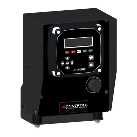
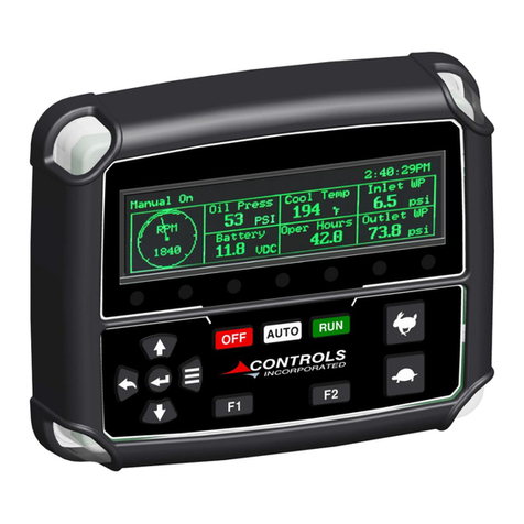
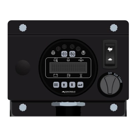
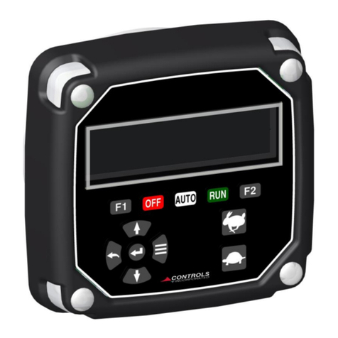
Controls G3-1015 User manual

Product Manual
Microprocessor-BasedGeneratorControlModule
For Electronic J1939 CANBusEngines
Part Number: G3-1015
Revision: 2.3
______________________________________________________________________________________________________________________________________
Copyright Controls, Inc.
P.O. Box 368 • Sharon Center, OH 44274
Phone 330.239.4345 • Fax 330.239.2845 • www.controlsinc.com

CONTROLS, INCORPORATED
C O N T R O L S Y S T E M S & S O L U T I O N S
- 1 -
1) Introduction
1.1 The G3-100 is a sealed microprocessor-based generator control system for electronic engines with J1939
CAN Bus. It is based on the Controls, Inc. uCAN series controller platform with a Freescale 8 bit processor.
1.2 The module is used for engine management and generator output display and is designed to be used with
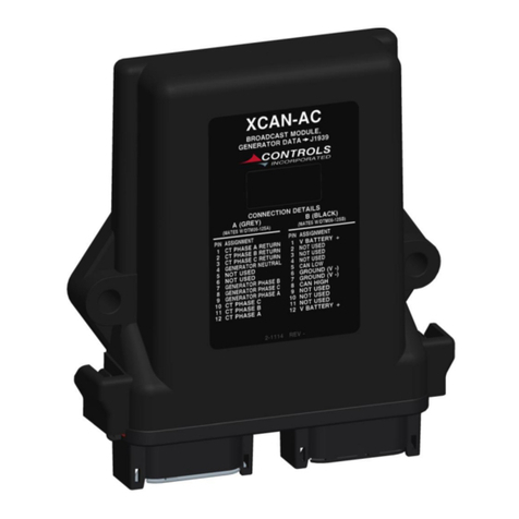
an XCAN-AC generator module.
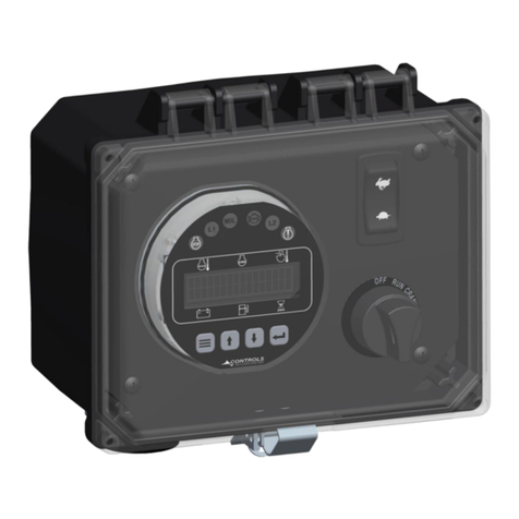
1.3 The product is packaged with electronics housed in water tight, polycarbonate enclosure for maximum
durability.
1.4 The digital display is 1”H x 4”W with two rows of 16 characters. Character height is approximately ½”. The
displayhas automatic temperature compensation for optimal viewing across the entire operating
temperature range of –20C to +70C. Backlight intensity is also adjustable. An extreme temperature option
is available, which extends the operating temp to –45C to +85C and the storage temp to –55C to +95C.
1.5 The unit monitors all critical engine functions and has full time display of Oil Pressure, Engine Temperature,
Battery Voltage, Fuel Rate, and Battery Voltage. AC Voltage, Phase, Current and Frequency are also
displayed for each line.
1.6 Analog Input is available for fuel level monitoring or other functionality.
1.7 Digital Input is available for customer configuration.
1.8 Engine speed control options include:
1.8.1 TSC Manual –Engine speed is controlled over the J1939 CAN Bus. Minimum and maximum
speed can be set in the panel along with the ramp rate.
1.8.2 TSC MultiState–Engine speed is controlled over the J1939 CAN Bus. Up to three unique speeds
can be programmed and incremented between using the up and down buttons.
1.8.3 Off –Engine speed is not adjusted using the panel.
1.9 Engine alarm codes are monitored with corresponding amber or red LED illuminations above the digital
display. Text messages along with the trouble code are displayed automatically.
CONTROLS, INCORPORATED
C O N T R O L S Y S T E M S & S O L U T I O N S
- 2 -
2) Interface
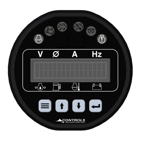
2.1 Display–The backlit digital display is 1”H x 4”W with two rows of 16 characters. Character height is
approximately ½”.
2.2 Display Parameters –The six full-time display parameters are:
∙ Oil Pressure ∙ BatteryVoltage
∙ Engine Temperature ∙ Fuel Rate / Fuel Level
∙ AC Voltage ∙ AC Amps
∙ Phase ∙ Frequency
2.3 Menu & Enter Buttons –To access and scroll menus.
2.4 Up & Down Buttons –For engine speed (Up & Down) and for menu navigation.
2.5 Amber (Pre Alarm) LED and Red (Alarm) LED located above the digital display.
uCAN Series
P/N G3-100

CONTROLS, INCORPORATED
C O N T R O L S Y S T E M S & S O L U T I O N S
- 3 -
3) Enclosure
3.1”uCAN” module is encased in a Sealed Polycarbonate Enclosure
.

CONTROLS, INCORPORATED
C O N T R O L S Y S T E M S & S O L U T I O N S
- 4 -
4) Complete Installation Kits
Installation kits are available which include the following
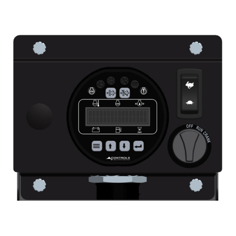
1) Control panel, P/N G3-2500 (Includes the G3-100 Module)
2) Generator monitor, P/N XCAN-AC
3) Current transformers, size and quantity depend on installation
4) Generator wiring harnesses, P/N 70-0670-5 (5 Foot)
5) Intermediate Harness, P/N 70-0671-5 (5 Foot)
PART NUMBER BREAKDOWN
G3 2500 803 K
Model
Enclosure
Package
CT Size (800:5)
And QTY (3)
“Kit” Includes Harnesses and
XCAN-AC Module
Five Foot Standard

CONTROLS, INCORPORATED
C O N T R O L S Y S T E M S & S O L U T I O N S
- 5 -
5) Panel Operation
5.1The panel is designed to monitor the engine when the operator keys on or starts the
engine.
5.1.1 Power Up –Unit performsa power up self-test. Initialization screen displays
firmware version. LEDs are illuminated forproper operation.
5.1.2 Acquiring Information –Panel synchsup to the J1939 CANBus. When no
information is present, the display shows dashed lines. The battery voltage is read
for the CAN Bus unless unavailable where it is then read directlyfrom the supply.
This process should not take longer than 1-2 seconds. Engine hours may not be
available forup to a 30 second period.

CONTROLS, INCORPORATED
C O N T R O L S Y S T E M S & S O L U T I O N S
- 6 -
5.1.3 Typical Operating Screen –The panel is synced up to the J1939 CAN Bus.
Engine information is updated continuously. Parameters such as oil pressure and
engine temperature can be configured to be displayed in Metric or English units.
Fuel rate is displayed in the absence of a fuel level sender or J1939 fuel level data.
5.1.4 Trouble Code Monitoring –If the engine ECU broadcasts a J1939 trouble code
(SPN.FMI) the panel will illuminate the appropriate LED indicator light and display
the code and message on the LCD screen. Occurrence count isalso displayed to
the right of the code.
Occurrence
Count
SPN.FMI
Text
Message

CONTROLS, INCORPORATED
C O N T R O L S Y S T E M S & S O L U T I O N S
- 7 -
5.1.5 Controller monitored shutdowns –If configured the module can shut down the
engine based on the engine parameters it is monitoring. Additionally, auxiliary
inputs are available foranalog fuel level monitoring and shutdown as well as a
switch input for other shutdown switches. Alarm events are recorded in the Alarms
Log Menu.
Over Speed Protection
Low Coolant Level Shutdown

CONTROLS, INCORPORATED
C O N T R O L S Y S T E M S & S O L U T I O N S
- 8 -
5.1.6 Display Options –The controller can display all three phases at the same time by
selecting the Gen Only screen option in the Module Configuration menu. Additional
generator information such as he following canbe accessed under the Generator
Parameters menu
Total Reactive Power
Power Factor
Total Apparent Power
Power Factor Phase (Lead or Lag)
Generated Power (Total kWH)
Amps A
Amps B
Amps C
kW
Volts A
Volts B
Volts C
Freq

CONTROLS, INCORPORATED
C O N T R O L S Y S T E M S & S O L U T I O N S
- 9 -
5.1.7 Throttle Operation –When operating throttle, a visual indication will be displayed
to assure the operator the module is responding to the request.
5.1.7.1TSC Manual or Momentary: Directional arrows will be used. If the engine speed
has reached a programmed maximum or minimum limit, an X will be shown.
5.1.7.2TSC MultiState: Engine starts at Speed 1 setting. Display will indicate each step
on the screen along with the programmed RPM setting requested.
5.1.7.3Off: Disables the controllers throttle capability.
Up Arrow
Down
Arrow

CONTROLS, INCORPORATED
C O N T R O L S Y S T E M S & S O L U T I O N S
- 10 -
6) 55) Controller Menus
5.1 The control panel a menus system to view various engine related information and set up the controller
programming. These menus are broken into two sections. Theyare operator menu and controller setup
menu. Thesemenus are accessible via the four-button pad located on the face of the control panel.
5.2 Operator Menu Ring –Password not required
Operator Menu Categories
Description
Generator Parameters
View detailed generator information
Active Engine Fault Codes
View active J1939 active codes
Stored Engine Fault Codes
View /clear J1939 stored codes
Operation Event Log
View last 32 events with run time stamp
Alarms Event Log
View last 32 alarms with run time stamp
Engine Parameters
View additional detailed engine information
Module Information
View model number firmware version
Controller Setup
Gain access tomodule programming
5.3 Controller Setup Menu Ring –Password required
Controller Setup Categories
Description
Input Configuration
View active J1939 active codes
Output Configuration
View /clear J1939 stored codes
Throttle Configuration
View last 32 events with run time stamp
Engine Safety Configuration
View last 32 alarms with run time stamp
Module Configuration
View additional detailed engine information
CAN Configuration
View and control emission system
Generator Calibration
Calibrate XCAN-AC Values
| = Exit Setup
Return to Operator Menu Categories

CONTROLS, INCORPORATED
C O N T R O L S Y S T E M S & S O L U T I O N S
- 11 -
5.4 Menu Access & Navigation
5.4.1 Accessing Menus
1. Press and hold the MENU key & simultaneously press the ENTER key.
5.4.2 Navigation
1. Press MENU to select the next menu category.
2. Press UP to view or edit the specific screen(s) in the category.
3. Press Down to step through logged events.
4. Use the UP and DOWN keys to move among the screens in the category.
5. Press MENU at any time within a category to jump back to the inner ring.
Stepping through menu categories

CONTROLS, INCORPORATED
C O N T R O L S Y S T E M S & S O L U T I O N S
- 12 -
Entering into category
Viewing logged events

CONTROLS, INCORPORATED
C O N T R O L S Y S T E M S & S O L U T I O N S
- 13 -
5.4.3 Password Entry
The password screen is provided to restrict the edit of sensitive values to authorized personnel.
Not entering a password permits viewing, but no editing of restricted values. Upon encountering
the password screen, a series of dashes will be displayed. To enter the password: [4345].
Entering password
1. Press ENTER to begin editing. The password zeroes will be bracketed.
2. Use the UP and DOWN keys to set the first (leftmost) digit, as you would for a cylinder
combination lock.
3. Press ENTER to freeze that digit and move to the next one on the right.
4. Repeat steps 2 and 3 until all four digits have been set. After the final digit is set, the brackets
automatically disappear.
5. Press the UP key to proceed to the next screens.
If the correct password was entered earlier, navigating back over the password entry screen will
show the password as a row of stars. The password approval state is retained as long as the
panel is powered up.
5.4.4 Editing
Some screens permit parameter changes.
1. Press ENTER to start editing. The value on the screen will be surrounded by brackets. On
password-protected screens, brackets appear only when the correct password was entered
earlier.
2. Use the UP and DOWN keys to adjust the value. In the case of a selection list, the various
possible selections will be shown in a ring. In the case of a variable number, press the
appropriate key to step up/down. For larger changes, press and hold the UP or DOWN key.
(The value will step faster as the key is held down. Stepping will stop when preset value limits
are reached or the key is released.)
3. Press ENTER to save the new value. The brackets will disappear.
4. To skip the edit and retain the old value, press MENU instead of ENTER.

CONTROLS, INCORPORATED
C O N T R O L S Y S T E M S & S O L U T I O N S
- 14 -
Leaving during editing will abandon the edit, and the old value will be retained.
5.4.5 Exiting
1. Press and hold the MENU key & simultaneously press the ENTER key.
Exiting the menus
Exiting has no effect on the password approval. To clear the approved password state,
power cycle the panel.

CONTROLS, INCORPORATED
C O N T R O L S Y S T E M S & S O L U T I O N S
- 15 -
7) Input Configuration
Heading
Default
Range
Units
Your Settings
Analog 1 Function
None
See Notes
Switch
Analog 1 Message
None
Off / Always / Run
Digital 1 Action
Auto Start
Notes
1) Off / Always / Run –Describes when the parameter will be monitored for alarm conditions. Run refers to when
the engine is running. Off disables the alarm conditions. Always enables the alarm constantlyregardless of engine
state.
2) Alarm Delay–The time period, after Sender Check Bypass, that the parameter must be on the alarm condition
before the alarm becomes latched.
3) Analog 1 Function Options
1) Fuel Level S-W –Fuel amount, in percentage can be measured and displayed on the C3 module using a
standard StewartWarner scale sender of 240 ohms –33 ohms. 240 = Emptyand 33 = Full. Sender
ground must be common with battery negative.
2) Fuel Level VDO –Fuel amount, in percentage can be measured and displayed on the C3 module using a
VDO scale sender of 10 ohms –180 ohms. 10 = Empty and 180 = Full. Sender ground must be common
with batterynegative.
3) Oil Pressure PSI –Oil pressure, in PSI, can be measured and displayed on the C3 module using a
standard StewartWarner scale sender of 240 ohms –33 ohms. 240 = 0 PSI and 33 = 100 PSI. Sender
ground must be common with battery negative.
4) Oil Pressure bar –Oil pressure, in bar, can be measured and displayed on the C3 module using a standard
StewartWarner scale sender of 240 ohms –33 ohms. 240 = 0 bar and 33 = 7 bar. Sender ground must
be common with battery negative.
5) Oil Pressure VDO PSI –Oil pressure, in PSI, can be measured and displayed on the C3 module using a
standard StewartWarner scale sender of 10 ohms –180 ohms. 10 = 0 PSI and 180 = 150 PSI. Sender
ground must be common with battery negative.
6) Oil Pressure bar –Oil pressure, in bar, can be measured and displayed on the C3 module using a standard
StewartWarner scale sender of 10 ohms –180 ohms. 240 = 0 bar and 33 = 10 bar. Sender groundmust
be common with battery negative.
7) Rheostat –Speed control can be accomplished byconnecting a 5 K potentiometer in series with the flex
analog input. Engine speed will vary with the change in resistance value.
8) 0 - 5 VDC –Reserved for OEM applications.
9) Ratiometric - Reserved for OEM applications.
10) 4-20mA - Reserved for OEM applications.
11) Switch –This setting allows for a switch to be connected rather than an analog sender. Set Analog 1
Message to assign a label to the switch device.
12) None –Set to None when no functionality is required.

CONTROLS, INCORPORATED
C O N T R O L S Y S T E M S & S O L U T I O N S
- 16 -
8) Output Configuration
Heading
Default
Range
Units
Your Settings
Relay1 Function
StartWarn
See RelayNotes
Relay1 Polarity
Positive
Positive / Invert
Relay1 Initial State
Off
Off / On
Relay2 Function
Fuel
See RelaySection
Relay2 Polarity
Positive
Positive / Invert
Relay2 Initial State
On
Off / On
Relay3 Function
Alarm
See RelaySection
Relay3 Polarity
Positive
Positive / Invert
Relay3 Initial State
Off
Off / On
Relay4 Function
Crank
See RelayNotes
Relay4 Polarity
Positive
Positive / Invert
Relay4 Initial State
Off
Off / On
Relay Notes:
A total of eight relays can be assigned for different uses depending on application. Two 10 amp relays and six 5
amp relays are used. Relay 2 and Relay4 are 10 amp, while Relays 1 / 3 and 5-8 are 5 amp. All relays use battery
plus to switch.
1) RelayFunctions –A total of four relays can be assigned for different uses depending on application.
a. None –Assign non when not used
b. Start Warning –Relay will be active during auto start delayperiod. Typically used to drive the low
side of an alarm horn or light.
c. Crank –Relay will be active during auto crank period. Used to drive a starter relay.
d. Preheat –Relay willbe active during programmed preheat period. Used to drive a preheat relay.
e. Fuel / Run –Relay will be active during an engine start request and while the engine is running.
Used to drive the engine’s ecu circuit. Also active when requesting active and stored J1939 codes.
f. Switch Trip –Relay will be active if digital input is active.
g. Engine Run –Relay will be active when engine RPM is greater than 600. Typically used to drive
an auxiliarycircuit such as louvers or send a signal to a monitoring station.
h. Alarm –Relay will be active when there is an alarm condition. Typicallyused to drive an alarm
horn or lamp. Also can be used to send a signal to a monitoring station
i. Prealarm –Relay will be active whenthere is a prealarm condition. Typically usedto drive an
alarm horn or lamp. Also can be used to send a signal to a monitoring station
j. Pre+Alarm Horn –Energizes an external audible alarm when a Prealarm or alarm condition is
present. Pressing the ENTER button will silence.
k. Alarm Horn –Energizes an external audible alarm when an alarm condition is present. Pressing
the ENTER button will silence.

CONTROLS, INCORPORATED
C O N T R O L S Y S T E M S & S O L U T I O N S
- 17 -
l. Low Oil Press Alarm –Relaycloses if a lowoil pressure shutdown is detected.
m. Hi Coolant Temp Alarm –Relaycloses if a high engine temperature shutdown is detected.
n. Overspeed Alarm –Relay closes if an overspeed shutdown is detected.
o. Over crank Alarm –Relay closes if an over crank alarm is detected.
p. LowFuel Level Alarm –Relaycloses if a low fuel level shutdown is detected.
q. Input 2-9 –Closes if the associated input is active..
r. Clutch 1 –Closes when Clutch 1 conditions are meet
s. Clutch 2 –Closes when Clutch 2 conditions are meet.
t. Throttle B1 –Reserved for OEM applications.
u. Throttle B0 –Reserved for OEM applications.
v. Custom 1 - Reserved for OEM applications.
2) RelayPolarity
a. Positive –Relay acts as a normally open contact.
b. Invert –Relayacts as a normallyclosed contact.
3) RelayInitialized State
a. On –Relay is activated upon power up.
b. Off- Relay is not activated upon power up.

CONTROLS, INCORPORATED
C O N T R O L S Y S T E M S & S O L U T I O N S
- 18 -
9) Throttle Configuration
Heading
Default
Range
Units
Your Settings
Throttle Type
TSC Vern
See Throttle Notes
TSC Mode
Primary
Primary / Secondary
TSC Min Speed
800
650 - 3000
TSC Max Speed
2400
650 - 3000
TSC Ramp Rate
100
10 - 2000
RPM/Sec
Throttle Curve
Linear
Linear / Exponential
Multistate Speed 1
650
650 - 3000
RPM
Multistate Speed 2
650
650 - 3000
RPM
Multistate Speed 3
650
650 - 3000
RPM
Multistate Speed 4
650
650 - 3000
RPM
Throttle Notes:
Multiple throttle types can be selected for operating in manual run mode. These include the following.
1) Throttle Types
a. TSC Vernier –Engine starts at minimum speed as set with TSC Min. Operator can increase and
decrease engine speed using up and down arrows. Maximum speed is limited to the TSC Max
setting. Changes in speed are affected byRamp Rate and Curve Type selected.
b. TSC Multistate –Engine starts at Speed 1. Operator can increment to the subsequent higher
speeds bymomentarily pressing the Up arrow. Decrementing to programmed speeds also
requires single presses of the down arrow. Changes in speed are affected byRampRate and
Curve Type selected.
c. TSC Hi-Lo Momentary –Engine starts at minimum speed as set with TSC Min. Pressing the up
arrow will accelerate the engine to TSC Max Speed and run at maximum speed while button is
pressed. Releasing the button will lower the speed to TSC Minimum RPM. Changes in speed are
affected byRamp Rate and Curve Type selected.
d. Flex-Analog –Using the Flex Analog input, a variable voltage signal (0-5 VDC) can be used to
control the engine RPM between TSC Min and TSC Max. A 4-20mA signal can be used, but
requires hardware modifications to the pcb. Alternatively, a normallyopen switch can be
connected to the flex-analog input. The engine RPM can be toggled between min and max
speeds based on the switches position. Open is min speed, closed is max speed. The Flex-
Analog function must be set to Rheostat for this throttle type to be activated.
e. Off –All throttle functionality can be disabled from the C3 module.
2) TSC Mode –Primaryvs. Secondary. Multiple C3 modules can be installed on the same engine allowing
multiple stations to control engine speed. Set the main controlpanel to Primaryand the other units to
secondary. The C3 modules will coordinate speed control between the different stations.
3) Auto Start Operation –When running in the auto start mode, automatic throttle will run in lieu of the manual
throttle type settings. See Auto Start Configuration for settings.

CONTROLS, INCORPORATED
C O N T R O L S Y S T E M S & S O L U T I O N S
- 19 -
10) Engine Safety Configuration
Heading
Default
Range
Units
Your Settings
Sender Check Bypass
0:10
0:05 –1:00
Min:Sec
Fuel Level Check
Off
Off / Always / Run
Low Fuel Prealarm
20
0 - 100
%
Low Fuel Alarm
1
0 - 100
%
Fuel Alarm Delay
0:05
0:01 –1:40
Sec
Oil Pressure Check
Off
Off / Always / Run
Low Oil Press Prealarm
15
0 - 100
PSI
Low Oil Press alarm
10
0 - 100
PSI
Oil Press Alarm Delay
5
0:01 –1:40
Sec
Temperature Check
Off
Off / Always / Run
Low Temp Prealarm
0
0 - 300
Deg F
Low Temp Alarm
0
0 - 300
Deg F
High Temp Prealarm
220
150 - 300
Deg F
High Temp Alarm
230
150 - 300
Deg F
Temp Alarm Delay
0:05
0:01 –1:40
Min:Sec
Battery Volts Check
Off
Off / Always / Run
Lo Battery Prealarm
12.0
0.0 –40.0
Volts
Hi Battery Prealarm
15.0
0.0 –40.0
Volts
Over Speed Check
Off
Off / Always / Run
Over Speed Alarm
3000
650 - 5000
RPM
Over Speed Alarm Delay
0:05
0:01 –1:40
Min:Sec
Notes
1) Off / Always / Run –Describes when the parameter will be monitored for alarm conditions. Run refers to when
the engine is running. Off disables the alarm conditions. Always enables the alarm constantlyregardless of engine
state.
2) Alarm Delay–The time period, after Sender Check Bypass, that the parameter must be on the alarm condition
before the alarm becomes latched.
Table of contents
Other Controls Control Unit manuals

Controls
Controls MVP-M702 User manual

Controls
Controls MVP-A3238 User manual

Controls
Controls MVP-A6235 User manual

Controls
Controls MVP-A3235 User manual

Controls
Controls MX Series User manual

Controls
Controls MVP-62303 User manual

Controls
Controls CX Series User manual

Controls
Controls XCAN-AC User manual

Controls
Controls J1939 User manual

Controls
Controls MVP-G342 User manual