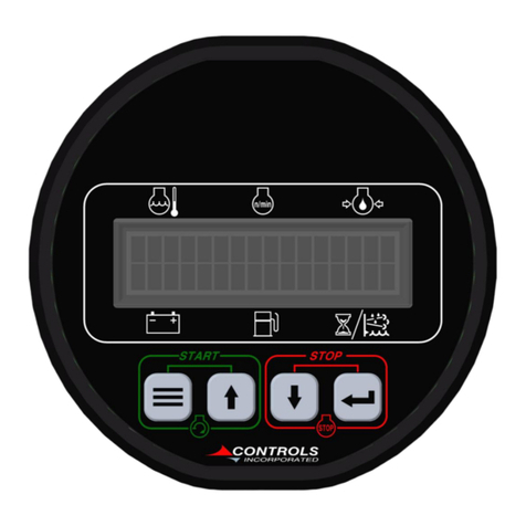
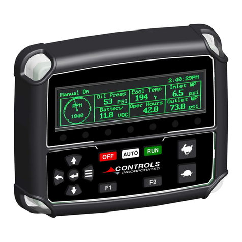
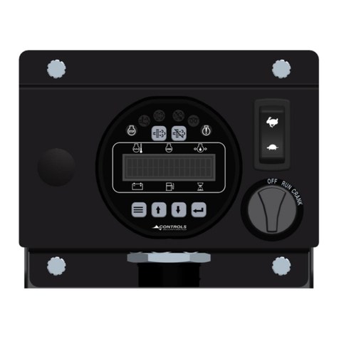
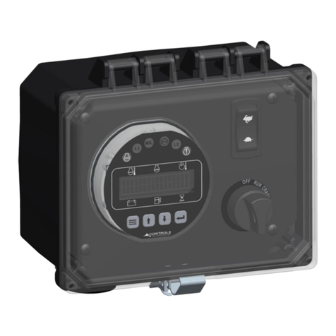
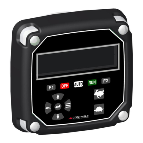
Controls MVP-G342 User manual

Product Manual
Part Number: MVP-G342
Revision: 1.0
______________________________________________________________________________________________________________________________________
Copyright Controls, Inc.
P.O. Box 368 • Sharon Center, OH 44274
Phone 330.239.4345 • Fax 330.239.2845 • www.controlsinc.com

1
TABLE OF CONTENTS
PRIOR TO ENGINE START………………...…………………………………………………………………….….…….……….…………...2
CAN Bus CONFIGURATION
THROTTLE SETTINGS…………………………..………………………………….……………………………………….….……………….....3
MANUAL OPERATION SPECIFICS
INSTALLATION INFORMATION……...........………………………………...……………………………………………………………....4
CONNECTOR INFORMATION……...........………………………………...………………………………………………………………….5
ENGINE ALARMS, CODES AND MESSAGES……………………………………………………………………………...……..7
ENGINE ECU ALARMS/DE-RATE/SHUT DOWNS
ALARM ANNUNCIATION AND CODE READER
PANEL INDICATION LAMPS
ACTIVE AND STORED ENGINE ECU CODES
CONTROL PANEL ANALOG AND DIGITAL INPUTS……………………………………………………………………..…9
MENU SYSTEM……………………………………………………………………………………………..…………………………………….……11
MENU ACCESS, EXIT AND NAVIGATION
MENUS TO VIEW INFORMATION
MENUS TO CONFIGURE MODULE SETTINGS

2
Prior to starting the engine, select the proper throttle control mode and parameters required
for application.
Generator Safety Configuration Menu
CAN Bus Configuration
This module communicates to the engine ECU via the J1939 CAN Bus network. This is a three
wire connection to the engine ECU. Engine information and alarmcodes are broadcast over the
CAN bus fromthe engine ECU to the controller display. And, the controller communicates throttle
commands to the engine ECU over the CAN bus.
To assure proper communications between the engine ECU and the controller, the correct
SOURCE ADDRESS and TSC1 ADDRESS need to be selected in the controller for the particular
engine make and model. These settingsare availablein the CAN CONFIGURATION MENU.
Generator Safety Configuration
Genset Rating (Default = 1 KW)
Genset Derate (Default = 0%)
AC Check Bypass (Default = 0:05)
High Frequency Check (Default = Off)
High Frequency Pre-alarm Setting (Default = 65.0 Hz)
High Frequency Alarm Setting (Default = 67.0 Hz)
High Frequency Alarm Delay (Default = 0:01)
Low Frequency Check (Default = Run)
Low Frequency Pre-alarm (Default = 55.0 Hz)
Low Frequency Alarm (Default = 53.0 Hz)
Low Frequency Alarm Delay (Default = 0:05)
Overcurrent Check (Default = Run)
Current Alarm Delay (Default = 0:05)
Current Tolerance (Default = 10%)
Voltage Check (Default = Run)
Voltage Alarm Delay (Default = 0:05)
High Current Pre-Alarm (Default = 9999 Amp)
High Current Alarm (Default = 9999 Amp)
Low Volt Pre-Alarm (Default = 0 Volt)
Low Volt Alarm (Default = 0 Volt)
High Volt Pre-Alarm (Default = 9999 Volt)
High Volt Alarm (Default = 9999 Volt)

3
INSTALLATION INFORMATION
CONNECTOR INFORMATION

4
BATTERY +
CAN HIGH
CAN LOW
N/A
FUEL LEVEL
BATTERY -
1
2
3
4
5
6
N/A
FUEL/RUN
N/A
N/A
OUTPUT 2
OUTPUT 3
1
2
3
4
5
6

5
ENGINE ALARMS, CODES AND MESSAGES
Engine ECU Alarm/De-Rate/Shut Downs
It isimportant to understand panel operation with respect to engine safety protections, alarms, and
fault codes. The panel operates with J1939 engines. These engines have an ECU (engine control
unit) which is essentially a computer that runs the engine. When engine parameters are outof
normal operating ranges, the ECU takes specific actions which can include the following:
1) Broadcast a trouble code
2) Broadcast a red or yellow lamp
3) De-rate the engine
4) Shut down the engine
5) Turn on alarmhorn
It isthe engine ECU that de-ratesor shuts down the engine whenit isnot operating within normal
parameters. Thisincludes more common shut downs like high engine temperature andlowoil
pressure but can encompass a large range of parameters depending on the ECU.
Alarm Annunciation and Code Reader
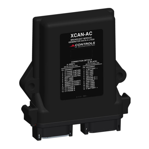
This panel is configured to operate with standard J1939 engines where engine de-rate and
shutdowns are managed by the engine ECU. The panel communicates with the engineECU and
serves as a trouble code reader. When the engine ECU broadcasts a trouble code (called an
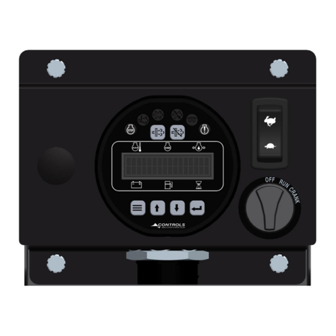
SPN.FMI code) the panel does the following:
1) Illuminate the appropriate LED indicator lamp
a. Yellow Lamp = Alarm
b. Red Lamp = Engine Shut Down
2) Displays the trouble code (standard SPN.FMI code)
3) Displays a code description on the LCD screen
4) Displays the occurrence count of the code
6
Indicator Lamps
.
Active and Stored Engine ECU Codes
The panel also provides the ability to check the engine ECU for all ACTIVE and STORED engine
ECU codes. These codes can be viewed via the Active Codesand Stored Codes menus.
Engine
Fault
Lamp
Engine
Alarm
Lamp
Regen
Active
Lamp
DPF
Lamp
Regen
Inhibit
Lamp
DEF
Lamp

7
CONTROL PANEL ANALOG AND DIGITAL INPUTS
The panel has one analoginput and up to one digital input available to monitor other components,
sendersor signals. Theseinputs can be used for a number of purposesincluding alarms and shut
downs.
Input
Heading
Default
Options
Connector
Pin
Digital 1
Normally
Open
Open / Closed
Accessory
1
Function
Alarm
Message
Custom
Check
Always
Off / Always / Run
2) Digital Function Activation
1) Off / Always / Run –Describeswhen the parameter will be monitored for alarm conditions.
Run refers to when theengineis running. Off disables the alarmconditions. Always enables
the alarm constantly regardless of engine state.
2) AlarmDelay –The time period, after Sender Check Bypass, that the parameter must be on
the alarmcondition before the alarmbecomes latched.
CONTROL PANEL RELAY OUTPUTS
The panel has threerelay outputs available to signal other devices basedon predefined
events. These Outputs can be used for a number of purposesincluding engine operation or
driving an audible alarm.
Input
Heading
Default
Connector
Pin
Relay 1
B
2
Function
Fuel Run
Polarity
Positive
Initial State
On
Input
Heading
Default
Connector
Pin
Relay 2
B
5
Function
None
Polarity
Positive
Initial State
Off
Input
Heading
Default
Connector
Pin
Relay 3
B
6
Function
None
Polarity
Positive
Initial State
Off

8
MENU SYSTEM
To Enter Menu System
Hold MENU button and press ENTER button.
Menu Navigation
Press MENU button to scroll menu options.
Press UP arrow button to enter menu.
Press DOWN arrow button to reverse.
Exit Menu System
Hold MENU button and press ENTER button.
To Change a Setting
Press ENTER button to bring up brackets [ ].
Press UP arrow button and DOWN arrow button to change setting.
Press ENTER button to make selection, brackets disappear.
Recycle key to the OFF position after changing a setting.

9
Main Menus
Main Menus
Sub Menus
Active Engine Fault Codes
View/Scroll Active Fault Codes
Stored Engine Fault Codes
View/Scroll Stored Fault Codes
Engine Parameters
View ECU Engine Information
(% Load, Torque, Oil Temp, etc.)
Engine Parameters
View Generator Information
(Power, Phase, etc.)
Emissions Parameters
Regen Options (Auto, Inhibit, Request)
DEF Level
Regen Active/Not Active View
Regen Inhibited/Not Inhibited View
DPF Out Gas Temperature View
DPF Differential Pressure View
Engine Identification
Engine Model # View
Engine Serial # View
Module Information
Control Unit Part# View
Control Unit Software Version View
Controller Setup
Quick Setup
(1)
(PASSWORD PROTECTED)
Engine Parameter Configuration
(2)
Generator Configuration
(3)
Input Configuration
(4)
Output Configuration
(5)
Throttle Configuration
(6)
Engine Safety Configuration
(7)
Generator Safety Configuration
(8)
Module Configuration
(9)
Display Configuration
(10)
CAN Configuration
(11)
Maintenance Configuration
(12)
Emissions Configuration
(13)
XCAN-AC Calibration
(14)
Clutch Configuration
(15)
To access the controller setup menus, a password is required.
Configuration
Menus
Viewing Menus

10
Configuration Menus
(1)
Quick Setup
Engine Type –Default = Electronic T3
Engine Mfg.
TSC Minimum Speed
TSC Maximum Speed
Performance Display
(2)
Eng. Parameter Configuration
Engine Type
Parameter Selection (Speed, Coolant Temp., Oil Pressure, Fuel
Level, Voltage, Hour Meter)
Parameter Setup (Varies based on parameter)
(3)
Generator Configuration
Phase Type
Voltage Type
Generator Pole Pairs
Generator Run Detect
Activation Frequency
Activation Delay
Deactivation Frequency
KWH Reset
(4)
Input Configuration
Configure Selection (Channels/Message)
Digital 1, 2, 3, 4 Setup
(5)
Output Configuration
Configure Selection (Channels/Message)
Relay 1 Function (Default to Fuel/Run)
Relay 2 Function
Relay 3 Function
(6)
Throttle Configuration
Throttle Type
Cooperative TSC Mode
TSC Minimum Speed
TSC Maximum Speed
TSC Bump Speed
TSC Ramp Rate
Throttle Curve
Multi State Speeds 1-4

11
(7)
Engine Safety Configuration
Sender Check By-Pass (Default = 0:10)
Oil Pressure Check (Default = Run)
Oil Pressure Alarm Action (Default = Shutdown)
Oil Pressure Alarm Delay (Default = 0:05)
Temperature Check (Default = Run)
Low Temperature Pre-Alarm (Default = 0 Deg.)
Low Temperature Alarm (Default = 0 Deg.)
High Temperature Pre-Alarm (Default = 240 Deg.)
High Temperature Alarm (Default = 240 Deg.)
Coolant Temperature Action (Default = Shutdown)
Temperature Alarm Delay (Default = 0:05)
Speed Limit (Default = 1600 rpm)
Torque Derate Limit (Default = 50%)
Low Oil Pressure Pre-Alarm (Default = 0 PSI)
Low Oil Pressure Alarm (Default = 1 PSI)
(8)
Generator Safety Configuration
Genset Rating (Default = 1 KW)
Genset Derate (Default = 0%)
AC Check Bypass (Default = 0:05)
High Frequency Check (Default = Off)
High Frequency Pre-alarm Setting (Default = 65.0 Hz)
High Frequency Alarm Setting (Default = 67.0 Hz)
High Frequency Alarm Delay (Default = 0:01)
Low Frequency Check (Default = Run)
Low Frequency Pre-alarm (Default = 55.0 Hz)
Low Frequency Alarm (Default = 53.0 Hz)
Low Frequency Alarm Delay (Default = 0:05)
Overcurrent Check (Default = Run)
Current Alarm Delay (Default = 0:05)
Current Tolerance (Default = 10%)
Voltage Check (Default = Run)
(9)
Module Configuration
Low Power Mode
Power Save Delay
Pre-Alarms Displayed (Default = 4)
Primary Run Source
Secondary Run Source
Check Run Criteria
Clear Operation Log (Default = No)
Clear Alarm Log (Default = No)
Clear # of Starts
Engine Run Criteria

12
(10)
Display Configuration
Display Mode
Voltage Display
English/Metric Selection
Performance Display Off/On
Fuel Display
(11)
CAN Configuration
Engine Manufacturer
TSC1 Address (Default = 3) Others available
Source Address (Default = 44) Others available
Engine Address (Default = 0) Others available
Speed Transmit On/Off
Temperature Transmit On/Off
Oil Pressure Transmit On/Off
Fuel Level Transmit On/Off
Voltage Transmit On/Off
Hours Transmit On/Off
Engine Status Transmit On/Off
Panel Status Transmit On/Off
Panel Information Transmit On/Off
Faults Transmit
Engine ID Auto Required
Can Bus Monitor
Transmit During Sleep
Panel Requests
Remember Speed Request
DTC Lamp Required
DTC Lamp Flashing
Service Faults
(12)
Maintenance Configuration
Service Messages
Schedule Selection
Schedule Reset
Schedule Interval
Schedule Warning
Schedule Trip
Schedule Message
(13)
Emissions Configuration
DEF Level Check (Default = Off)

13
Low DEF Pre Alarm (Default = 16%)
Low DEF Alarm (Default = 0%)
DEF Alarm Delay
Allow Service Regeneration Yes/No (Deere Only)
Regeneration Interlock On/Off
TSC Transmit Yes/No (stop TSC to engine during regeneration)
DPF Inhibit Lamp Source
(14)
XCAN-AC Calibration
Call Controls, Inc. for Details
(15)
Clutch Configuration
Clutch #1 Engage Trip (Default = None)
Clutch #1 Engage Speed (Default = 800 rpm)
Clutch #1 Engage Load (Default = 0%)
Clutch #1 Engage Coolant Temperature (Default = 150°F)
Clutch #1 Engage Delay (Default = 0:00)
Clutch #1 Engage Interval (Default = 0:00)
Clutch #1 Release Trip (Default = None)
Clutch #1 Release Speed (Default = 800 rpm)
Clutch #1 Release Load (Default = 0%)
Clutch #1 Release Coolant Temperature (Default = 150°F)
Clutch #1 Release Delay (Default = 0:00)
Clutch #1 Release Interval (Default = 0:00)
Table of contents
Other Controls Control Unit manuals

Controls
Controls CX Series User manual

Controls
Controls XCAN-AC User manual

Controls
Controls MVP-62303 User manual

Controls
Controls G3-1015 User manual

Controls
Controls XL-500E-AS User manual

Controls
Controls J1939 User manual

Controls
Controls MVP-A3238 User manual

Controls
Controls MX Series User manual

Controls
Controls MVP-A6235 User manual

Controls
Controls MVP-M702 User manual