EXFO FTV-700 series User manual

User Guide
OTDR for FTB-1
FTB-700 Series

ii FTB-700 Series
Copyright © 2006–2011 EXFO Inc. All rights reserved. No part of this
publication may be reproduced, stored in a retrieval system or transmitted
in any form, be it electronically, mechanically, or by any other means such
as photocopying, recording or otherwise, without the prior written
permission of EXFO Inc. (EXFO).
Information provided by EXFO is believed to be accurate and reliable.
However, no responsibility is assumed by EXFO for its use nor for any
infringements of patents or other rights of third parties that may result from
its use. No license is granted by implication or otherwise under any patent
rights of EXFO.
EXFO’s Commerce And Government Entities (CAGE) code under the North
Atlantic Treaty Organization (NATO) is 0L8C3.
The information contained in this publication is subject to change without
notice.
Trademarks
EXFO’s trademarks have been identified as such. However, the presence
or absence of such identification does not affect the legal status of any
trademark.
Units of Measurement
Units of measurement in this publication conform to SI standards and
practices.
Patents
EXFO’s Universal Interface is protected by US patent 6,612,750.
Version number: 17.0.4

Contents
OTDR iii
Contents
Certification Information ..................................................................................................... viii
1 Introducing the FTB-700 OTDR .................................................................... 1
Main Features .........................................................................................................................2
Trace Acquisition Modes .........................................................................................................3
Optional Software Packages ...................................................................................................3
Data Post-Processing ..............................................................................................................4
Bidirectional Analysis Application ...........................................................................................4
OTDR Basic Principles ..............................................................................................................5
Conventions ............................................................................................................................7
2 Safety Information ....................................................................................... 9
General Safety Information .....................................................................................................9
Laser Safety Information .........................................................................................................9
3 Getting Started with Your OTDR ............................................................... 11
Inserting and Removing Test Modules ..................................................................................11
Starting Module Applications ...............................................................................................15
Timer ....................................................................................................................................16
4 Preparing Your OTDR for a Test ................................................................. 17
Installing the EXFO Universal Interface (EUI) .........................................................................17
Cleaning and Connecting Optical Fibers ...............................................................................18
Naming Trace Files Automatically .........................................................................................20
Enabling or Disabling the First Connector Check ..................................................................24
Setting Macrobend Parameters .............................................................................................25
5 Testing Fibers in Auto Mode ...................................................................... 27
6 Testing Fibers in Advanced Mode ............................................................. 31
Setting the Autorange Acquisition Time ...............................................................................36
Setting the IOR, RBS Coefficient, and Helix Factor ................................................................37
Setting Distance Range, Pulse Width, and Acquisition Time .................................................39
Enabling the High-Resolution Feature ...................................................................................43
Enabling or Disabling Analysis After Acquisition ...................................................................45
Setting Pass/Fail Thresholds ..................................................................................................47
Setting a Default Span Start and Span End ...........................................................................52

Contents
iv FTB-700 Series
7 Testing Fibers in Template Mode (optional) ..............................................55
Template Principle .................................................................................................................55
Restrictions of Template Mode ..............................................................................................56
Acquiring the Reference Trace ..............................................................................................58
Acquiring Traces in Template Mode ......................................................................................60
Selecting a Reference Trace ...................................................................................................68
8 Testing Fibers in Fault Finder Mode ...........................................................69
Acquiring Traces in Fault Finder Mode ..................................................................................69
Naming Fault Finder Files Automatically ...............................................................................72
Selecting the Default File Format for the Fault Finder Traces .................................................74
Enabling or Disabling the Confirmation of Fault Finder File Name ........................................76
Enabling or Disabling the Storage Feature ............................................................................78
Enabling or Disabling the First Connector Check for Fault Finder .........................................79
Enabling or Disabling the Touchscreen Keyboard ..................................................................81
Setting Trace Display Parameters ..........................................................................................82
Selecting the Distance Units .................................................................................................84
9 Customizing Your OTDR ..............................................................................87
Selecting the Default File Format ..........................................................................................87
Enabling or Disabling File Name Confirmation .....................................................................88
Selecting the Distance Units .................................................................................................90
Customizing the Acquisition Distance Range Values .............................................................92
Customizing the Acquisition Time Values .............................................................................94
Enabling or Disabling the Touchscreen Keyboard ..................................................................96
Displaying or Hiding the Optional Features ..........................................................................97

Contents
OTDR v
10 Analyzing Traces and Events ..................................................................... 99
Graph View .........................................................................................................................100
Linear View .........................................................................................................................102
Summary Table ...................................................................................................................104
Events Tab ...........................................................................................................................106
Measure Tab .......................................................................................................................110
Trace Info. Tab ....................................................................................................................110
Displaying the Graph in Full Screen ....................................................................................111
Selecting the Default View ..................................................................................................113
Automatically Displaying the Event Table after Acquisitions ...............................................115
Automatically Zooming in on the Fiber Span ......................................................................116
Using Zoom Controls ..........................................................................................................117
Setting Trace Display Parameters ........................................................................................120
Customizing the Event Table ...............................................................................................122
Displaying or Hiding a Trace ...............................................................................................124
Clearing Traces from the Display .........................................................................................126
Viewing and Modifying Current Trace Settings ...................................................................127
Modifying Events ................................................................................................................132
Inserting Events ..................................................................................................................136
Deleting Events ...................................................................................................................138
Managing Comments .........................................................................................................140
Changing the Attenuation of Fiber Sections .......................................................................142
Setting the Analysis Detection Thresholds ..........................................................................144
Analyzing or Reanalyzing a Trace ........................................................................................147
Analyzing the Fiber on a Specific Fiber Span .......................................................................149
Enabling or Disabling the Detection of Reflective Ends of Fiber ..........................................150
Swapping Traces .................................................................................................................154
Opening Trace Files .............................................................................................................155
11 Analyzing the Results Manually .............................................................. 159
Selecting the Attenuation and Loss Values that Will Be Displayed ......................................159
Using Markers .....................................................................................................................161
Getting Event Distances and Relative Powers ......................................................................162
Getting Event Loss (Four-Point and Least-Square Approximation) ......................................163
Getting Attenuation (Two-Point and Least-Square Approximation) ....................................168
Getting Reflectance ............................................................................................................170
Getting Optical Return Loss (ORL) .......................................................................................171
12 Managing Trace Files from the OTDR Test Application .......................... 173
Saving a Trace in a Different Format ...................................................................................173
OTDR Trace File Compatibility .............................................................................................174
Copying, Moving, Renaming, or Deleting Trace Files ..........................................................176

Contents
vi FTB-700 Series
13 Creating and Generating Reports ............................................................177
Adding Information to the Test Results ...............................................................................177
Generating a Report ..........................................................................................................179
14 Using the OTDR as a Light Source ............................................................185
15 Analyzing Traces with the
Bidirectional Analysis Application (Optional) .........................................189
Starting and Exiting the Bidirectional Analysis Application .................................................191
Creating Bidirectional Measurement Files ...........................................................................193
Opening Existing Bidirectional Measurement Files ..............................................................197
Displaying Traces and Bidirectional Measurement ..............................................................198
Viewing Results ..................................................................................................................200
Reanalyzing Traces and Regenerating the Bidirectional Measurement ................................211
Modifying the Alignment of Unidirectional Traces ..............................................................213
Using Zoom Controls ..........................................................................................................217
Using Markers to Edit Events ..............................................................................................221
Inserting Events ..................................................................................................................223
Modifying Events ................................................................................................................227
Deleting Events ...................................................................................................................231
Changing the Attenuation of Fiber Sections .......................................................................233
Setting General Parameters ................................................................................................236
Customizing the Events Table .............................................................................................239
Saving the Span-Start and Span-End Information ...............................................................242
Setting Pass/Fail Thresholds ................................................................................................243
Modifying Trace Analysis Settings .......................................................................................248
Saving Traces ......................................................................................................................253
Exporting Unidirectional Traces from Bidirectional Files ......................................................255
Adding Information to the Test Results ...............................................................................257
Creating Reports .................................................................................................................259
16 Maintenance ..............................................................................................263
Cleaning EUI Connectors ....................................................................................................264
Verifying Your OTDR ...........................................................................................................266
Recalibrating the Unit .........................................................................................................274
Recycling and Disposal (Applies to European Union Only) ..................................................275
17 Troubleshooting ........................................................................................277
Contacting the Technical Support Group ............................................................................280
Transportation ....................................................................................................................281

Contents
OTDR vii
18 Warranty ................................................................................................... 283
General Information ...........................................................................................................283
Liability ...............................................................................................................................284
Exclusions ...........................................................................................................................284
Certification ........................................................................................................................284
Service and Repairs .............................................................................................................285
EXFO Service Centers Worldwide ........................................................................................286
A Technical Specifications ........................................................................... 287
B Description of Event Types ...................................................................... 289
Span Start ..........................................................................................................................290
Span End ...........................................................................................................................290
Short Fibers .......................................................................................................................290
Continuous Fiber ...............................................................................................................291
End of Analysis ..................................................................................................................292
Non-Reflective Event ..........................................................................................................293
Reflective Event .................................................................................................................294
Positive Event .....................................................................................................................295
Launch Level ......................................................................................................................296
Fiber Section ......................................................................................................................297
Merged Event ....................................................................................................................298
Echo ..................................................................................................................................304
Reflective Event (Possible Echo) .........................................................................................305
Index .............................................................................................................. 307

Certification Information
viii FTB-700 Series
Certification Information
FCC Information
Electronic test equipment is exempt from Part 15 compliance (FCC) in
the United States. However, compliance verification tests are
systematically performed on most EXFO equipment.
Information
Electronic test equipment is subject to the EMC Directive in the European
Union. The EN61326 standard prescribes both emission and immunity
requirements for laboratory, measurement, and control equipment.
This unit has undergone extensive testing according to the European Union
Directive and Standards.

Certification Information
OTDR ix
Application of Council Directive(s): 2006/95/EC - The Low Voltage Directive
2004/108/EC - The EMC Directive
2006/66/EC - The Battery Directive
93/68/EEC - CE Marking
And their amendments
Manufacturer’s Name: EXFO Inc.
Manufacturer’s Address: 400 Godin Avenue
Quebec, Quebec
Canada, G1M 2K2
(418) 683-0211
Equipment Type/Environment: Test & Measurement / Industrial
Trade Name/Model No.: (PON FTTx / MDU OTDRs) / FTB-700 SERIES
Standard(s) to which Conformity is Declared:
EN 61010-1:2001 Edition 2.0 Safety Requirements for Electrical Equipment for Measurement,
Control, and Laboratory Use, Part 1: General Requirements.
EN 61326-1:2006 Electrical Equipment for Measurement, Control and Laboratory
Use - EMC Requirements – Part 1: General requirements
EN 60825-1:2007 Edition 2.0 Safety of laser products – Part 1: Equipment classification,
requirements, and user’s guide
EN 55022: 2006 + A1: 2007 Information technology equipment - Radio disturbance
characteristics - Limits and methods of measurement
I, the undersigned, hereby declare that the equipment specified above conforms to the above Directive and Standards.
Manufacturer
Signature:
Full Name: Stephen Bull, E. Eng
Position: Vice-President Research and
Development
Address: 400 Godin Avenue, Quebec (Quebec),
Canada, G1M 2K2
Date: August 18, 2010
DECLARATION OF CONFORMITY

OTDR 1
1 Introducing the FTB-700 OTDR
The FTB-700 OTDR allows you to characterize a fiber-optic span, usually
optical fiber sections joined by splices and connectors. The optical time
domain reflectometer (OTDR) provides an inside view of the fiber, and can
calculate fiber length, attenuation, breaks, total return loss, and splice,
connector and total losses.
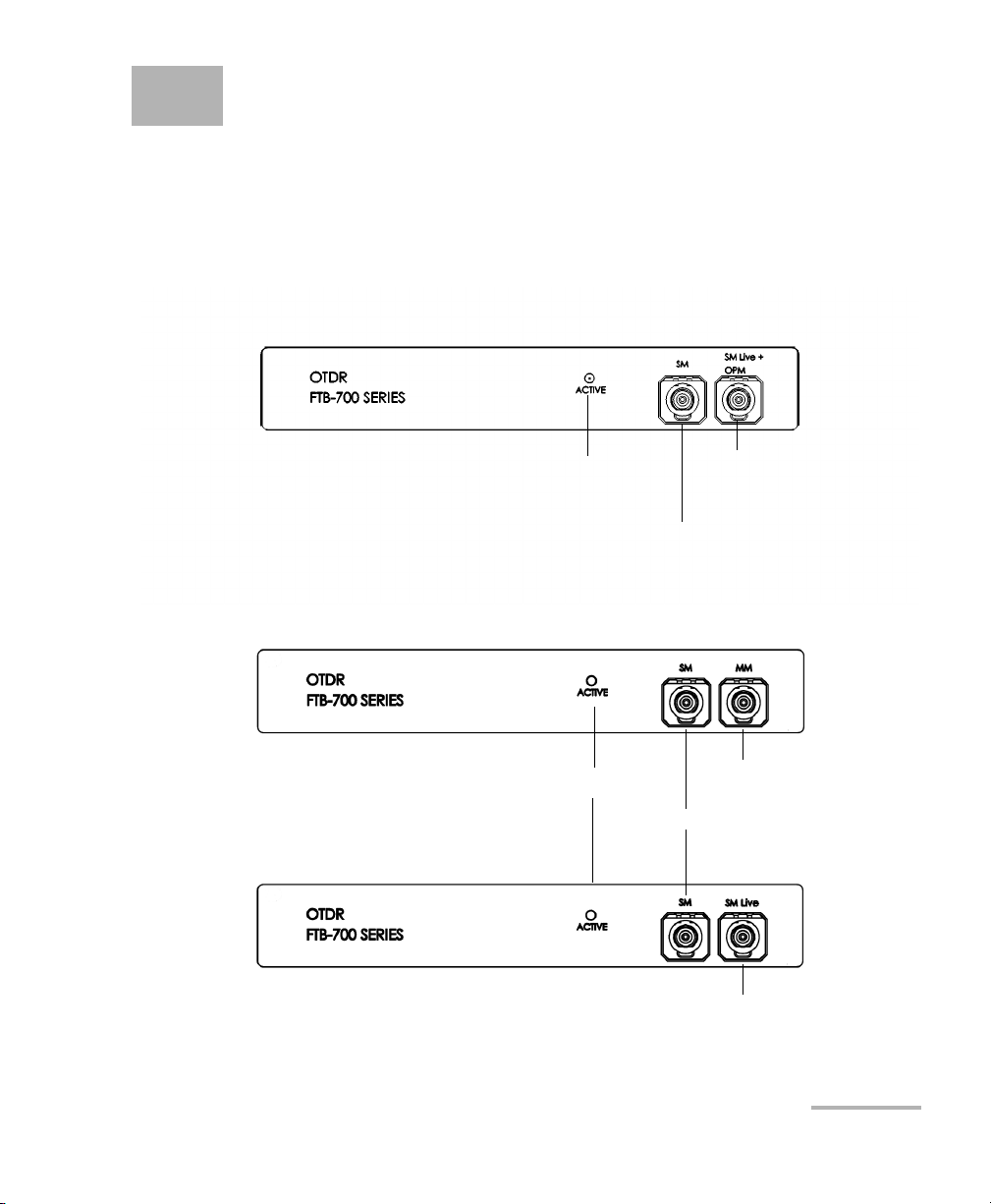
OTDR port (singlemode)
OTDR port (singlemode
live and On-line power
meter)
Active LED
FTB-720
FTB-730
OTDR port (singlemode)
OTDR port (multimode)
Active LED
OTDR port
(singlemode live)

Introducing the FTB-700 OTDR
2FTB-700 Series
Main Features
Main Features
The OTDR:
³Offers impressive dynamic range with short dead zones.
³Performs quick acquisitions with low noise levels to enable accurate
low-loss splice location.
³Acquires OTDR traces made of up to 256 000 points that provide a
sampling resolution as fine as 4 cm.
³Includes a light source.

Introducing the FTB-700 OTDR
OTDR 3
Trace Acquisition Modes
Trace Acquisition Modes
The OTDR application provides the following trace acquisition modes:
³Auto: Automatically calculates fiber length, sets acquisition
parameters, acquires traces, and displays event tables and acquired
traces.
³Advanced: Offers all the tools needed to perform integral OTDR tests
and measurements and gives you control over all test parameters.
³Template (optional): Tests fibers and compares the results to a
reference trace that was previously acquired and analyzed. This allows
you to save time when testing a large number of fibers. Reference trace
documentation is also automatically copied to new acquisitions.
³Fault Finder: Rapidly locates fiber ends and displays the length of the
fiber under test. This allows you to perform quick tests without having
to set all the acquisition parameters.
Optional Software Packages
There are two optional software packages offered with the application.
With the optional Auto Diagnostic (AD) software package you can:
³Have access to the “linear view”, which displays the events
sequentially, from left to right.
³Find macrobends and view the related information.
³View the summary table, which gives, for each wavelength, the global
status of the results, the span loss and span ORL values.
³Test in Fault Finder mode, to rapidly locate fiber ends.

Introducing the FTB-700 OTDR
4FTB-700 Series
Data Post-Processing
With the optional Event Characterization (EC) software package you can:
³Have access to the OTDR Bidirectional application and perform a
bidirectional analysis on two unidirectional OTDR traces.
³Test in Template Mode, test fibers and compare the results to a
reference trace.
Data Post-Processing
You can install the LiteReporter (available on the DVD that came with your
product) on a computer to view and analyze traces without having to use
an FTB-1 and an OTDR. You can also access more features such as:
³customized printout
³batch printing
³conversion of traces to many formats such as Telcordia or ASCII
Bidirectional Analysis Application
Note: This function is available with the optional Event Characterization (EC)
software package only.
You can improve the accuracy of your loss measurements with the
bidirectional analysis application. This utility uses OTDR acquisitions from
both ends of a fiber span (singlemode traces only) to average loss results
for each event.

Introducing the FTB-700 OTDR
OTDR 5
OTDR Basic Principles
OTDR Basic Principles
An OTDR sends short pulses of light into a fiber. Light scattering occurs in
the fiber due to discontinuities such as connectors, splices, bends, and
faults. An OTDR then detects and analyzes the backscattered signals. The
signal strength is measured for specific intervals of time and is used to
characterize events.
The OTDR calculates distances as follows:
where
c = speed of light in a vacuum (2.998 x 10⁸m/s)
t = time delay from the launch of the pulse to the reception of the
pulse
n = index of refraction of the fiber under test (as specified by the
manufacturer)
Distance c
n
---t
2
---
×=

Introducing the FTB-700 OTDR
6FTB-700 Series
OTDR Basic Principles
An OTDR uses the effects of Rayleigh scattering and Fresnel reflection to
measure the fiber’s condition, but the Fresnel reflection is tens of
thousands of times greater in power level than the backscatter.
³Rayleigh scattering occurs when a pulse travels down the fiber and
small variations in the material, such as variations and discontinuities
in the index of refraction, cause light to be scattered in all directions.
However, the phenomenon of small amounts of light being reflected
directly back toward the transmitter is called backscattering.
³Fresnel reflections occur when the light traveling down the fiber
encounters abrupt changes in material density that may occur at
connections or breaks where an air gap exists. A very large quantity of
light is reflected, as compared with the Rayleigh scattering. The
strength of the reflection depends on the degree of change in the index
of refraction.
When the full trace is displayed, each point represents an average of many
sampling points. You will have to zoom to see each point.
Microprocessor
Pulse
generator
Avalanche
photodetector (APD)
Display
Reflections come back
to the OTDR
Set of
instructions
Light pulses Light pulses
Analog-to-digital
converter (A/D)
Returned signal
Analyzed signal
Laser
diode
Optical
coupler
OTDR
port
Fiber

Introducing the FTB-700 OTDR
OTDR 7
Conventions
Conventions
Before using the product described in this manual, you should understand
the following conventions:
WARNING
Indicates a potentially hazardous situation which, if not avoided,
could result in death or serious injury. Do not proceed unless you
understand and meet the required conditions.
CAUTION
Indicates a potentially hazardous situation which, if not avoided,
may result in minor or moderate injury. Do not proceed unless you
understand and meet the required conditions.
CAUTION
Indicates a potentially hazardous situation which, if not avoided,
may result in component damage. Do not proceed unless you
understand and meet the required conditions.
IMPORTANT
Refers to information about this product you should not overlook.


OTDR 9
2 Safety Information
General Safety Information
Laser Safety Information
Your instrument is a Class 1M laser product in compliance with standards
IEC 60825-1 and 21 CFR 1040.10. Invisible laser radiation may be
encountered at the output port.
The product is safe under reasonably foreseeable conditions of operation
but it may be hazardous if you use optics within a diverging or collimated
beam. Do not view directly with optical instruments.
WARNING
Do not install or terminate fibers while a light source is active.
Never look directly into a live fiber and ensure that your eyes are
protected at all times.
WARNING
Use of controls, adjustments and procedures for operation and
maintenance other than those specified herein may result in
hazardous radiation exposure or impair the protection provided by
this unit.
Affixed to module’s
side panel

Table of contents
Other EXFO Test Equipment manuals

EXFO
EXFO LETP-700 Series User manual

EXFO
EXFO MaxTester series Operation and maintenance manual

EXFO
EXFO FOT-12 User manual

EXFO
EXFO MaxTester Max-610 User manual

EXFO
EXFO FVA-60B User manual

EXFO
EXFO bv10 User manual

EXFO
EXFO Optical Explorer OX1 Operating manual

EXFO
EXFO FTB-200 User manual

EXFO
EXFO ARU-100 User manual

EXFO
EXFO FTB-200 User manual

EXFO
EXFO IQ-2600B User manual

EXFO
EXFO IQS-8500 Series User manual

EXFO
EXFO LTB Series User manual

EXFO
EXFO FTBx-88000 Series User manual

EXFO
EXFO EX Series User manual

EXFO
EXFO LTS-3900 User manual

EXFO
EXFO AXS-200/850 User manual

EXFO
EXFO FTB-860 User manual

EXFO
EXFO AXS-200/635 User manual

EXFO
EXFO BRT-320 User manual


