CONVECTAIR OPERA B User manual

OPÉRA B
RADIANT TOWEL WAMER
421AA4940 A00
INSTALLATION AND
USER GUIDE
Installation and Warranty Card
To be read and retained by the user.

Dear user,
Thank you for your trust and congratulations on the
purchase of your new CONVECTAIR electric heater.
We design and manufacture the highest quality
devices in the electrical industry.
For the ultimate in comfort, and for maximum
performance from your devices, please read the
installation and operating instructions included in
this manual.
Thank you.
WARNING: Your heater is already equiped with
a precise electronic thermostat. IT MUST NOT BE
CONNECTED TO A WALL THERMOSTAT.
MESSAGE
FROM THE MANUFACTURER

The smart technology that electric heating lacked.
Your Opera B device is compatible with the Muller Intuitiv
technology that uses the detection sensor of compatible
Convectair heaters to understand your lifestyle and to suggest
concrete and appropriate measures to save energy.
Compatibility with voice assistants.
Download the Muller Intuitiv with Netatmo application on
your smartphone, insert the module (sold separately) into the
compartment provided at the back of compatible electric
heaters and use voice control via Apple Home Kit, Alexa
and Google Assistant.
Keep an eye on your energy consumption.
By tracking down even the smallest unnecessary energy
expenditure in your home, Convectair devices with Muller
Intuitiv smart technology will help you save energy.
Smart and optimized home.
Maximize your savings with precise room-by-room temperature
control, smart planning of heating using temperature settings
and customized alerts.
COMPATIBILITY
SMART ENERGY MANAGEMENT
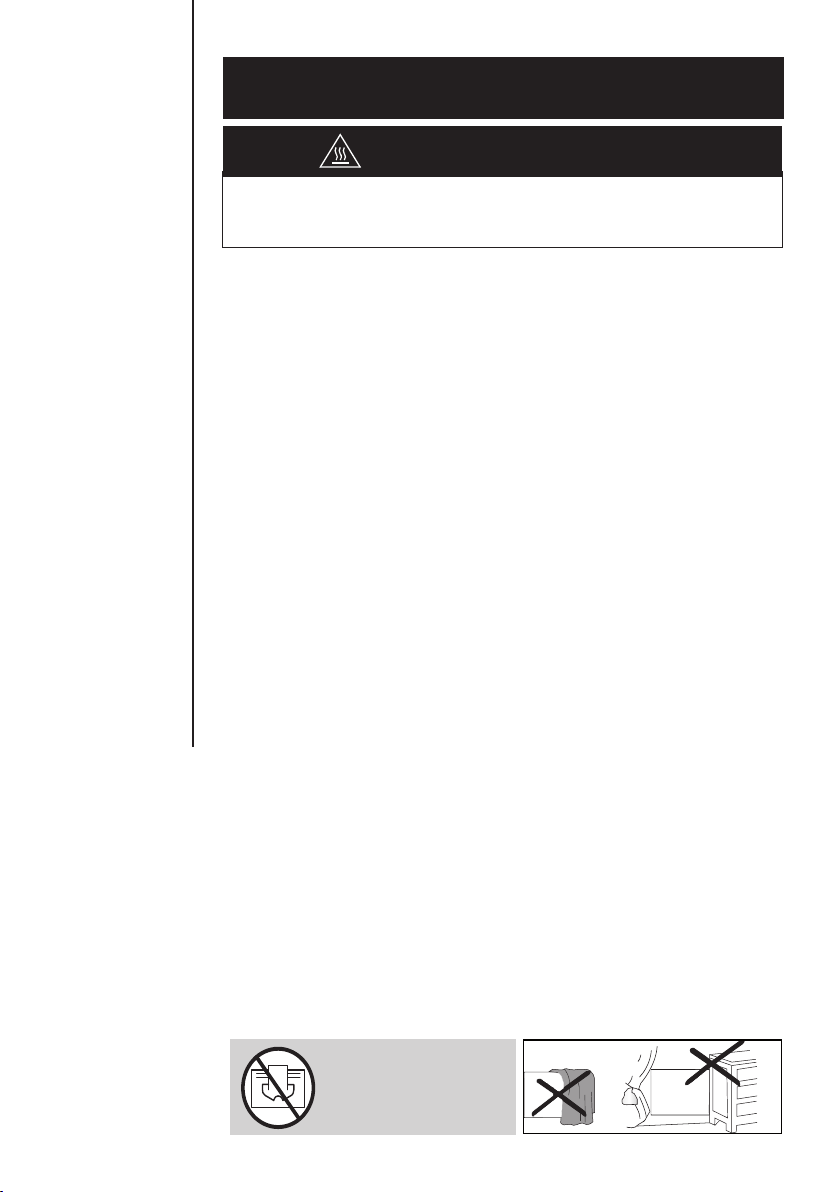
IMPORTANT:
DO NOT COVER
THE HEATER
Please read carefully the whole installation and
operating instructions and in particular the following.
CAUTION, HOT SURFACE
ATTENTION: Some parts of the appliance may become hot
and cause light burns. A very close attention has to be taken if
children or vulnerable persons are present.
1. This appliance is not intended for use by persons (including
children) with reduced physical, sensory or mental
capabilities, or lack of experience and knowledge, unless
they have been given supervision or instruction concerning
use of the appliance by a person responsible for their
safety.
2. Children under the age of three should be kept away from
the appliance, unless they are continuously supervised.
3. Children from three to eight years old should neither play,
nor plug, nor set, nor clean, nor maintain the appliance.
4. If the appliance is covered, there is a risk of overheating.
The logo reminds this risk.
5. Do not cover or obstruct the air inlet or outlet as this could
cause overheating and damage the appliance.
6. Do not insert anything in the appliance.
7. ;OPZHWWSPHUJLOHZ[VILJVUULJ[LKI`HX\HSPȹLK
WLYZVUULS;\YUVȸ[OLIYLHRLYHZZVJPH[LK[V[OL\UP[
before connecting or repair.
8. Installation and electrical connections must be in
accordance with the national and local codes.
9. The electrical current should be protected by a residual
current device in the case of an installation in a bathroom
with a bathtub, shower or sink.
10. The heater must not be installed below an electrical socket.
11. This heating device is deisgned to provide ambiant heat for
new or existing residential or commercial type building.
12. Do not install the heater in a zone with air currents capable
of disrupting its regulation.
1. SAFETY
MEASURES TO BE TAKEN

20 cm
(8")
Any obstacle
ex: curtains
Floor
C
15 cm
(6")
B
2.5 cm
(1")
E
15 cm
(6")
B
75 cm
(30")
A
Minimum
clearances In front
(A) Sides
(B) Above
(C) Underneath
(E) Recommended
height
7635-C10-BB 75 cm
(30 in)
15 cm
(6 in)
20 cm
(8 in)
2.5 cm
(1 in)
25 cm
(10 in)
7635-C15-BB 75 cm
(30 in)
15 cm
(6 in)
20 cm
(8 in)
2.5 cm
(1 in)
25 cm
(10 in)
HEATER INSTALLATION: This heater must be
installed in accordance with national and
local codes and CONVECTAIR recommends an
PUZ[HSSH[PVUI`HX\HSPȹLKLSLJ[YPJPHU
CAUTION: PLEASE MAINTAIN THE MINIMUM REQUIRED CLEARANCES (Fig. A).
CONVECTAIR RECOMMENDS AN INSTALLATION HEIGHT OF 25 CM (10").
These instructions have been established at the moment of the heater’s
manufacturing and in conformity with the standardization at that moment.
!
Fig. A
Volume 0
Volume 1
Hors volume
Outside volume
0,5 m
1' 8"
0,5 m
1' 8"
2,25 m * - 7' 5" *
Volume 2
Ύ,ĂƵƚĞƵƌăƉĂƌƟƌĚƵĨŽŶĚĚĞůĂďĂŝŐŶŽŝƌĞ
,ĞŝŐŚƚĨƌŽŵƚŚĞďŽƩŽŵŽĨƚŚĞďĂƚŚ
Fig. A2
13. Minimum installation
KPZ[HUJLZ[V[OLȺVVY
walls, furniture, etc., must
be respected. -PNf(. If
the device is installed in a
bathroom or powder room
(Fig. A2), it must be installed
V\[ZPKLVM]VS\TLfH[H
TPUPT\TKPZ[HUJLVMfT
from the bathtub and/or
ZOV^LYHUKT\Z[ILȹ[[LK
^P[OHJSHZZ(KPȸLYLU[PHS
circuit breaker.
(IMPORTANT: See applicable
national and local codes).

Capacity
Hole
spacing
cm / (in)
A
cm / (in)
B
cm / (in)
C
cm / (in)
D
cm / (in)
1000 W
24.8
(9-3/4)
11.6
(4-5/8)
46.8
(18-3/8)
32.7
(12-7/8)
11.6
(4-5/8)
1500 W
24.8
(9-3/4)
11.6
(4-5/8)
46.8
(18-3/8)
38.7
(15-1/4)
11.6
(4-5/8)
To install your heater at 25 cm (10 in) from the ground
(recommended height by CONVECTAIR), follow these directions:
1- Free mounting brackets by pressing and pulling both locking
tabs on the back of the heater (Fig. B).
2- Place the center of the mounting bracket's bottom holes (no.
2 Fig. B2) at the measure C (see Fig. B) from the ground and
make a mark.
3- Check horizontality of the mounting bracket, then mark the
two top holes and pierce the 4 holes for fastening.
4- Replace mounting bracket and fasten it appropriately with
screws (not included).
The installation must comply with applicable national and local
standards, and CONVECTAIR recommends that it be done by a
JLY[PȹLKLSLJ[YPJPHU
This manual was prepared at the time of manufacture of the
device and in accordance with the standards applicable at the
time.
The company reserves the right to modify at any time the
Installation and User Guide to account for standards and their
evolution.
;VH]VPKZOVY[JPYJ\P[ZWSLHZL[\YUVȸ[OLWV^LY
at the electrical panel prior to installation or repair.
If the power cable is damaged, it must be replaced by the
manufacturer, its after-sales service personnel or a similarly
X\HSPȹLKWLYZVU[VH]VPKHU`KHUNLY
If the device has a glass front, do not use if the glass front is
damaged.
2.
INSTALLATION AND MOUNTING
MEASURES TO BE TAKEN

28
B
104
258
2
AA
500=>1250W
Measure C
2
A
BARRE INFÉRIEURE À INSÉRER
PAR LE HAUT DE L’APPAREIL.
(Vis prémontées sur la carrosserie)
1
1
BARRE SUPÉRIEURE À INSÉRER
PAR LE HAUT DE L’APPAREIL
(Vis prémontées sur la carrosserie)
2
2
Installation of towel rails
Floor
A
B
C
D
Hole spacing
Outline
of unit
Height
Width
25.4 cm
(10")
55.8 cm
(22")
Junction
Box
Locking
tab
Figure B
Figure B3
Bottom rail to be inserted
over the unit’s top
(preassembled screws).
Top rail to be inserted
over the unit’s top
(preassembled screws).
Please read carefully the whole installation and
operating instructions before connecting the heater.
!
Figure B2

f^PYL
or FAS
f
300 volts
approved.
B - Black
G - Green
R - Red
C - Copper
P (PW) - Purple
B - Black
G - Green
R - Red
C - Copper
P (PW) - Purple
R
R
B
B
C
POWER
G
P*
CANADA
WITH the use pilot wire (PW)
R
R
DEVICE
B
B
C
P
G
CANADA
WITHOUT the use pilot wire (PW)
DEVICE
POWER
CONVECTAIR recommends that your heater be installed by a
X\HSPȹLKLSLJ[YPJPHUHUKPUHJJVYKHUJL^P[OUH[PVUHSHUKSVJHS
codes.
This heater must be connected to a 240 Volt (60 cycles) circuit
and with an appropriate breaker. Cut all electrical current
before connecting the heater to avoid shocks and damages to
the unit.
;OLȹYZ[[PTL`V\Y*VU]LJ[HPYOLH[ZHSPNO[ZTVRLJV\SKIL
released due to the burning of production residues. This is
normal and should disappear after 2 to 3 minutes.
WARNING: To prevent short circuits and electrical shocks
[\YU[OLWV^LYVȸH[[OLTHPUWHULSILMVYLH[[LTW[PUN[OL
installation or making any repairs. This programmer system is
old technology and will not work on this new generation.
- You must connect the ground wire of the heater (green wire)
with the copper wire.
- Connect the power cables to the red and black cables.
- Never connect the pilot-wire (purple wire) to the electrical
supply nor ground it.
- The purple wire with the seal at the extremity should not be
used for the electrical connection. It is used only if the heater is
connected with other CONVECTAIR units for synchronisation of
heating schedule and temperatures.
- Fix the unit on the wall bracket before turning the power
back on.
3.
CONNECTION
MEASURES TO BE TAKEN

4.
QUICK START
MEASURES TO BE TAKEN
ACTIONS PRESS DISPLAY
Switch the heating
VUVYVȸ
Set the temperature.
Modes
To switch from one mode
to another.
Comfort mode
To adjust to the desired
set point.
Economy mode
Recommended for
absences of less than
fOY
Frost protection mode
Recommended for
HIZLUJLZTVYL[OHUfOY
“Open window”
To enable or disable
the function.

5.1 SWITCHING ON AND OFF
PRESS ACTIONS DISPLAY
Switching on.
The green indicator lights up
and the screen displays
:^P[JOPUNVȸ
The orange indicator lights up
and the screen displays
This indicator shows that your device is heating
up. When the desired temperature has
Z[HIPSPaLKP[SPNO[Z\WHUK[\YUZVȸIHZLKVU
heating needs.
NOTE
The device stores the settings in the memory,
even in the case of a power outage.
5.
OPERATION
MEASURES TO BE TAKEN
)LZ\YL[VYLTV]L[OLWYV[LJ[P]LȹSTMYVT[OLKPZWSH`
Selection of
manual
operation modes
Automatic
operation key
Heating
6U6ȸRL`
Desired
temperature
setting keys
Heating
6U6ȸ
indicator light
Programs
WYLKLȹULK777
\ZLYKLȹULK777
Behavioral
indicator
“Open window”
function
Heating
indicator
light
Module
compartment
for future
optional use
Other manuals for OPERA B
1
Table of contents
Other CONVECTAIR Bathroom Fixture manuals


