Cookology CEI1100SS User manual

1
CEI1100SS
CEI110WGP CEI110BGP
Cooker hood
Instruction manual

2
CONTENT
1……………………………………….Notice
2……………………………………….Feature
3………………………………………..Installation
4………………………………………..Notice of installation
5………………………………………..Safety Warning
6…………………………………………Speed adjustment
7…………………………………………Maintenance
8…………………………………………Abnormity and Solution

3
1.Notice
This appliance can be used by
children aged from 8 years and above
and persons with reduced physical,
sensory or mental capabilities or lack
of experience and knowledge if they
have been given supervision or
instruction concerning use of the
appliance in a safe way and
understand the hazards involved.
Children shall not play with the
appliance. Cleaning and user
maintenance shall not be made by
children without supervision
If the supply cord is damaged, it must
be replaced by the manufacturer, its
service agent or similarly qualified
persons in order to avoid a hazard.

4
The instructions shall state the
substance of the following:
– there shall be adequate ventilation
of the room when the range hood is
used at the same time as appliances
burning gas or other fuels (not
applicable to appliances that only
discharge the air back into the room);
– the details concerning the method
and frequency of cleaning;
– there is a fire risk if cleaning is not
carried out in accordance with the
instructions;
– do not flambé under the range hood;

5
– CAUTION: Accessible parts may
become hot when used with cooking
appliances.
The installation instructions shall
include the substance of the
following:
– the air must not be discharged into a
flue that is used for exhausting fumes
from appliances burning gas or other
fuels (not applicable to appliances
that only discharge the air back into
the room);
– the minimum distance between the
supporting surface for the cooking
vessels on the hob and the lowest part
of the range hood. (When the range
hood is located above a gas appliance,
this distance shall be at least 65 cm.
– regulations concerning the

6
discharge of air have to be fulfilled.
The installation instructions for range
hoods with accessible metallic
enclosures of class II construction
shall include details that indicate the
location and maximum permitted
lengths for any fixing or mounting
screw or other fixing device that
penetrates into the range hood to
attach an accessory such as a facia or
duct fitting.
Where fixing or mounting screws, or
other fixing devices are used, that
penetrate into the range hood with an
accessible metallic enclosure of class
II construction, to attach an accessory,
the instructions shall indicate the
required location of these screws or
fixing devices and include the

7
substance of the following warning.
Warning: Failure to install the screws
or fixing device in accordance with
these instructions may result in
electrical hazards.
2. Feature
1. The cooker hood uses high quality materials, and is made with a
streamlined design.
2. Equipped with a large power low noise electric motor and
centrifugal leaf, it produces strong suction, low noise, non stick grease
filter and easy to clean.
3. Special wind tunnel construction and oil collector design, free dirt
will be absorbed in a second.
3. Installation
MOUNTING OF THE V-FLAP
If the cooker hood does not have an assembled V-flap 1, you should
mount the half-parts to its body. The images only show an example of
how to mount the V-flap, the outlet may vary according to different
models and configurations.
To mount the V-flap 1 you should:
• Mount two half-parts 2 into the body 6
• the pin 3 should be top oriented;
• the axis 4 should be inserted into the holes 5 on the body;
• repeat all the operations for the 2nd half-part

8
INSTALLATION
1. Before installation, turn the unit off and unplug it from the outlet.
2. The cooker hood should not be placed at a distance of no more than
150cm from the cooking surface for the best performance. Refer to Pic
1.
3. The ceiling must bear at least 120KGs weight, and the thickness of the
ceiling must be ≥30MM.

9
4. According to the size shown on pic 2, drill 14pcs φ8mm holes on the
ceiling once the installation height is determined,14pcs explode screws(or
14pcs ST6*40mm big flat screws+14pcs wall plugs) will be used to fix
the two hanging board on the ceiling.( see pic. 3)
5. Calculate the length of the angle iron (refer to pic 4/5),then 32pcs of
M4*10 screws and M4 nut with gasket will be used to connect the angle
iron into the adjustable angle iron bracket. (Make sure the overlap length
of angle iron cannot less than 36mm)
6. As pic 9 shown, choose the direction of the outlet①/②/③/④
a. Refer to Pic 7, open the decorative plate in order, and take out the filter.
b. Refer to Pic 8, unscrew and take away the 4 pcs ST4*8mm screws that
on the panel decorative strip.
c. Unscrew the 8pcs machine silk from the bottom of the cabinet housing
and rotate it by 90°/180°/270° to choose the direction of the outlet, then
screw the 8 pcs machine silk to fix the housing well;

10
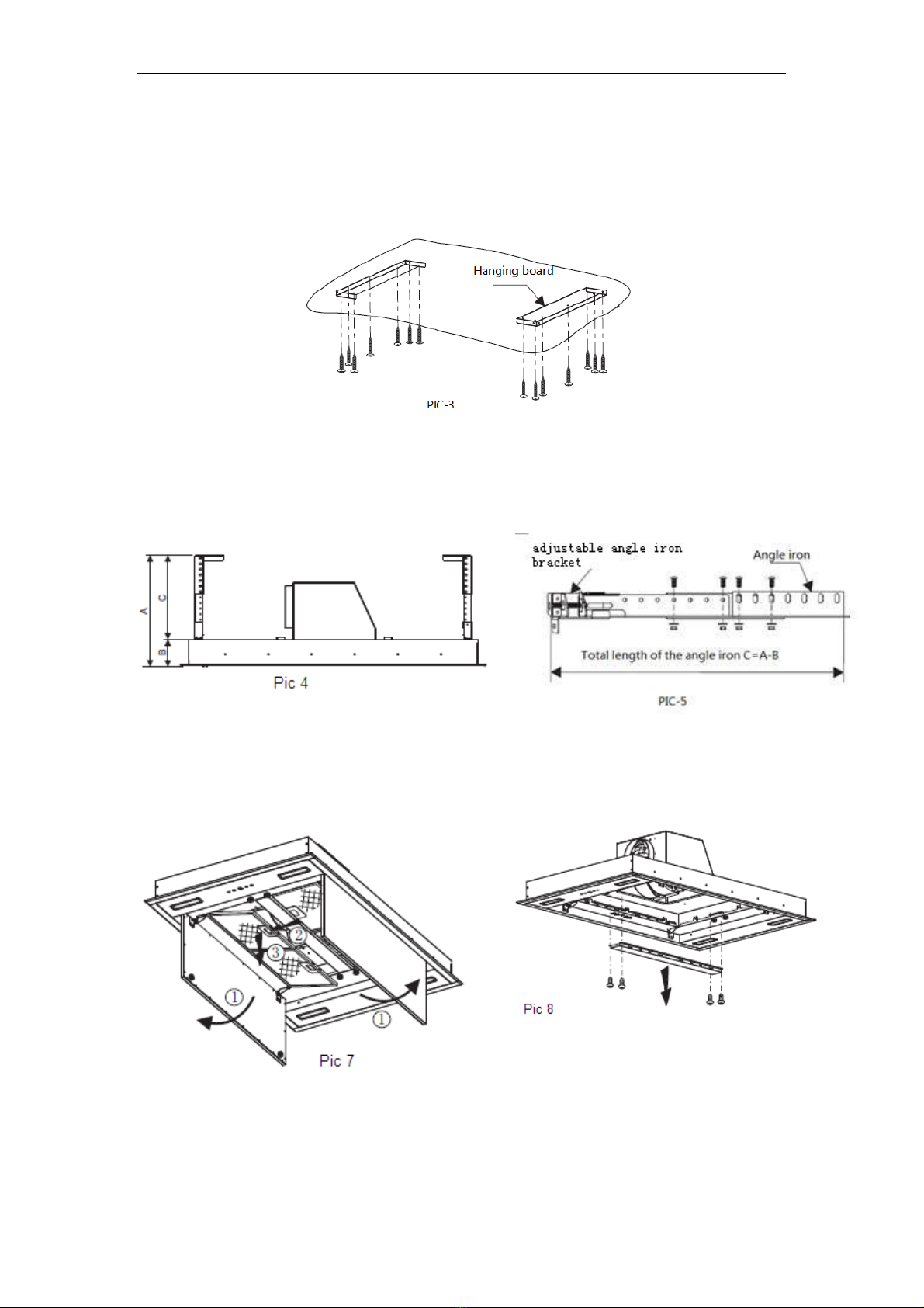
d. Install the panel decorative strip and filter well apply to the reverse
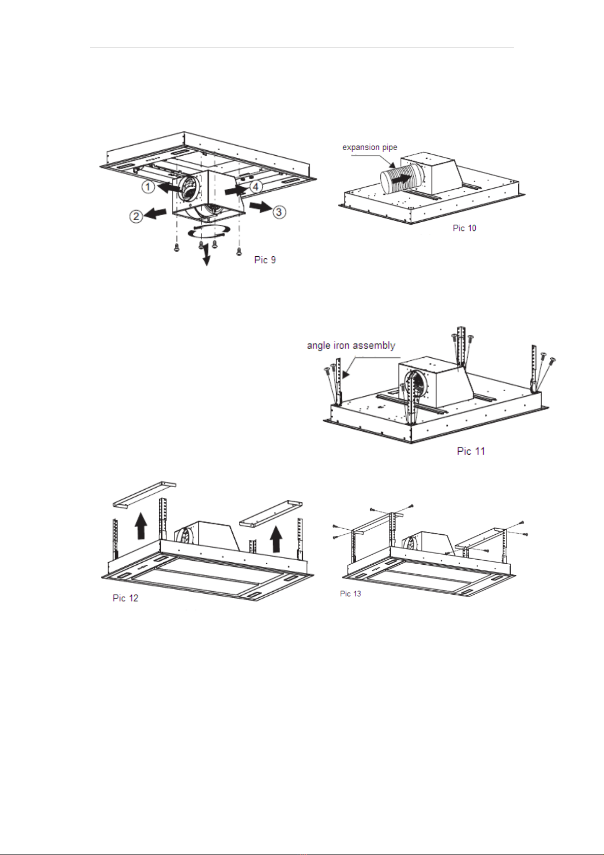
order of a/b steps above. Meanwhile, install the expansion pipe to the
outlet (refer to pic 10).
7. As pic 11 shown, connect the 4 adjustable angle iron bracket with the
housing by 8pcs M4*12mm
machine silk screw, next refer to
pic 12/13, lift up the housing, use
8pcs M4*12mm machine silk screw
and M4 nut with gasket to fix the
housing onto the 2 hanging board,
meanwhile, pull the expansion pipe
outside. (Note: The expansion pipe
must be fixed on the housing
firmly.)
8. After installing the housing to the hanging board, use cross screwdriver
or straight screwdriver to adjust the screw of the angle iron bracket, direct
the housing level position and height till it is suitable. Adjust method:
Adjust rang of the angle iron bracket is 0-25mm, clockwise twist the
screw of the 4 angle iron bracket, slightly move the housing upwards;
meanwhile, anticlockwise twist the screw of the angle iron bracket,
slightly move the housing downwards. Use the cross screwdriver to screw
the safety screw tightly after the level position and height is suitable.
(Refer to pic 14)

11
4. Notice of installation
1. Before installation, please ensure the area is clean to avoid suction
of the remaining bits of broken wood and dust.
2. It cannot share the same air ventilation tube with other appliance
such as gas tube, warmer tube, and hot wind tube.
3. The bending of ventilation tube should be≥120°, parallel or above
the start point and should be connected to the external wall.
4. After installation, make sure that the extractor is level to avoid
grease collection at one end.
5. Safety Warning
In certain circumstances electrical appliances may be a danger hazard.
•Keep electrical appliances out of reach from Children or infirm
persons. Do not let them use the appliances without supervision.
•This appliance is not intended for use by persons (including children)
with reduced physical. Sensory or mental capabilities, or lack of
experience and knowledge, unless they have been given supervision
or instruction concerning use of the appliance by a person responsible
for their safety.
•Do not touch the light bulbs when/after appliance use.
•Do not check the status of the filters while the cooker hood is
operating
•Flame cooking is prohibited underneath the cooker hood
•Your cooker hood is for domestic use only, not suitable for barbecue,
roast shop and other commercial use.
•Any installation work must be carried out by a qualified electrician or

12
competent person.
•Before cleaning, always ensure that you have switched your cooker
hood off.
•Clean the cooker hood according to the instruction manual and keep
the cooker hood from the danger of burning.
•No fire for drying your cooker hood.
•If there is any fault with your cooker hood, please call the service
department appointed by agent for servicing.
•If the power cord is damaged, it must be replaced by the manufacturer
or a qualified service engineer in order to avoid a hazard.
•Do not exhaust the gas from cooker hood through the same heated
flue which is for the gas from gas hob and other kitchen appliances.
•Before installation and usage, read all the instructions and make sure
that the voltage (V) and the frequency (Hz) indicated on your cooker
hood are exactly the same as the voltage (V) and the frequency (Hz)
in your home.
•Regulations concerning the discharge of air have to be fulfilled.
•CAUTION: Accessible parts may become hot when used with
cooking appliances.
•Attention! Observe the warning in the instruction sheet concerning
the operation of the appliance when air is discharged from the room.
•Regarding the instructions for the bulb changing, pls use the same
bulb and ILCOS D code for this lamp is DBS-2/65-H-120/33.
6. Speed adjustment
Electronic button with LED display & remote
After connecting to power, the control panel will be lighted and the
buzzer will sound once. The output is off and the hood enters into standby
mode.
On/Off
Switches the ventilation on and off.
Light
Switches the light on and off. Please note the
Lamp is not under control of the on/off
button.

13
Ventilation
speed
The motor has the low speed, mid. speed and
high speed.
When the hood is working with low speed,
LED display will show 1.
Press the button, then the hood will transfer to
the mid speed for working; the LED will
show 2 , press the speed button again , the
hood will transfer to the high speed for
working immediately. And so on…
Timer
This is a 9 minute timer. When the hood is
working, press this button to set a time for
motor operation. press the button , LED
display will be shown 9.8.7.6 ...decreasing by
1,when time is up,the motor will cut off at
once automatically and the lamp will
extinguish. If pressing “Timer” button, the
hood will go in or go out “Timer” function.
Connecting the remote control
A New remote control has to establish a new connection to the cooker
hood when used for first time. One remote control could possibly
control several cooker hood at the same time.
Connection process between remote control and cooker hood
Within 15S after the cooker hood connects to the power supply, long
press for 5 seconds, the indicators light begin flashing from one
button to another ,the cooker hood is in connection mode, press any
button on remote control to confirm the connection. The connection
process finished and the remote control can be used for speed
selection, lighting and timer setting.
If you want to connect again, you will need to clear the code that has
been set up previously.
To clear the code, press for 5 seconds, the indicators light begin
flashing from one button to another, the cooker is in connection mode.
Then, press again for 5 seconds, the previous connection code is
cleared.
When the previous code has been cleared, the cooker hood back to
standby mode, press for 5 seconds, the indicate light flashing from

14
one button to another ,the cooker hood is in connection mode, then,
press any button on remote control to confirm the connection.
Remote control
1. Lighting
press button once, the light is on, press again, the light is off.
The lighting button it is controlled separately and will not affect any
other functions.
2. Turning on/ Increasing motor speed key , the motor has low,
mid, high totally 3 levels.
2.1 Press one time,the motor will work at low speed (Turning
on).
2.2When the hood works at low speed, touch again,the motor
changes to mid speed.
2.3Base on the middle speed condition, touch again, the motor is
running in the high speed.
2.4Base on the high speed condition, touch again,the hood still
works at high speed.
3. Turning off/Decreasing motor speed key
3.1 press the button and the motor begins shift to a lower speed
and the LCD screen display the speed level. Repeating press the button, it
keep on decreasing the motor speed till the cooker hood turning off.
4. Low speed, mid speed and high speed cannot work at the same time.
When hood is on high speed, press the speed decrease, it will turn to a

15
lower speed; when it is in low speed, press the speed increase, it will turn
to a higher speed.
5. Timer
Press the button to set up the timer on/off function.
7. MAINTENANCE
1. It is recommended to operate the appliance prior to cooking.
2. It is recommended to leave the appliance in operation for 15 minutes
after cooking is terminated in order to completely eliminate cooking
vapors and odors.
3. The proper function of the cooker hood is conditioned by the
regularity of the maintenance operations, in particular, the active
carbon filter.
4. The anti-grease filters capture the grease particles suspended in the air,
and are therefore subject to clogging according to the frequency of the
use of the appliance.
5. The cooker hood must regularly cleaned on both the inside and outside
with hot water plus non corrosive detergent (AT LEAST ONCE A
MONTH) to protect the main body from corrosion over a long period
of time.
Attention! Please do not use abrasive detergent or alcohol as it will
damage the body.
Attention! Keep the motor and other spare parts free from water, as this
will cause damage to the appliance.
Attention! Before cleaning the appliance please remember to cut off the
power.

16
6.Changing and cleaning the anti-grease filters
-Removing the filters as the instruction of picture.
You can clean the filter as below measure:
Soak them for about 3 minute in hot water (40-50 degrees) with a mild
detergent and then brush it gently with a soft brush. Please do not
apply too much pressure so as to avoid any damage to it.
Note: Please do not use abrasive detergent for it will damage the hood;
Make sure that the hood is shut off before cleaning.
CARBON FILTER-not supplied
Activated carbon filter can be used to trap odors. Normally the activated
carbon filter should be changed every 3 to 6 months according to your
cooking habits. The installation procedure of activated carbon filter is as
below:
In order to install the activated carbon filter, the aluminium filter should
be detached first. Firstly open carefully the stainless steel cover, then
press the lock of aluminium filter and remove it.

17
NOTE:
•Make sure the filter is securely locked. Otherwise, it would loosen and
cause danger.
•When activated carbon filter attached, the suction power will be
lowered.
BULB REPLACEMENT
Important :
The bulb must be replaced by the
manufacturer, its service agent or similarly
qualified persons.
Always switch off the electricity supply before
carrying out any operations on the appliance.
When handling bulb, make sure it has
completely cooled down before any direct
contact to hands.
When handling blubs hold with a cloth or
gloves to ensure perspiration does not come
in contact with the blub as this can reduce
the life of the blub.
Changing a lamp bulb for LED
•Switch off the appliance and make sure it’s disconnected from the
mains supply.
•You should use a suitable screwdriver to pry up one end of the
light and take it out for replacement.
• ILCOS D code for this lamp is: DSS-1.5/65-S-120/33
– LED modules –rectangle lamp
– Max wattage: 4×1.5 W
– Voltage range: DC 12V
– Dimensions:

18
8.Abnormity and Solution
Fault
Cause
Solution
Light on, but motor
does not work
The leaf blocked
Get rid of the blocking
The capacitor damaged
Replace capacitor
The motor jammed bearing
damaged
Replace motor
The internal with of motor off or
a bad smell from the motor
Replace motor
Light does not work,
motor does not work
Beside the above mentioned, check the following:
Light damaged
Replace lights
Power cord looses
Connect the wires as per
the electric diagram
Oil leakage
One way valve and the air
ventilation entrance are not
tightly sealed
Take down the one way
valve and seal with glue
Leakage from the connection
of U-shaped section and
cover
Take U-shaped section
down and seal with soap
or paint
Shake of the body
The leaf damaged and causes
shaking
Replace the leaf
The motor is not tightly
hanged
Lock the motor tightly
The body is not tightly
hanged
Fixed the body tightly
Insufficient suction
The distance between the
body and the gas top too long
Readjust the distance
Too much ventilation from
open doors or windows
Choose a new place and
resemble the machine
The machine inclines
The fixing screw not tight
enough
Tighten the hanging
screw and make it
horizontal
The hanging screw not tight
enough
Tighten the hanging
screw and make it
horizontal

19
ENVIRONMENTAL PROTECTION:
This product is marked with the symbol on the selective sorting of
waste electronic equipment. This means that this product must not
be disposed of with household waste but must be supported by a
system of selective collection in accordance with Directive
2002/96/EC. It will then be recycled or dismantled to minimize impacts
on the environment, electrical and electronic products are potentially
dangerous for the environment and human health due to the presence of
hazardous substances.
For more information, please contact your local or regional authorities.
Note:
a. In order to reduce the environmental impact (e.g. energy use) of the
cooking process, please be sure that your product is installed according
to the user manual, keep the operation place ventilated, keep the
extraction duct be direct and short as possible as it can be.
b. For the product with manual operation mode, we suggest switch the
motor off within 10 minutes after finishing the cooking process.
c. Please be sure to dismantle related components according to the user
manual when maintaining for non-destructive, protect the parts to make
the re-installed work can be favoring and avoid damage.
This manual suits for next models
2
Table of contents
Other Cookology Ventilation Hood manuals

Cookology
Cookology BUGL520BK User manual

Cookology
Cookology LINT1001BK User manual

Cookology
Cookology PREM900BK User manual

Cookology
Cookology CHA600BK User manual

Cookology
Cookology TEL600SS/A User manual

Cookology
Cookology ANG605SS User manual

Cookology
Cookology CDD600BK User manual

Cookology
Cookology CGL100BK User manual

Cookology
Cookology BUCH520SS User manual

Cookology
Cookology CEI1100BK User manual