CoolLED pE-400 Series User manual

DOC-075 Iss 1
User Manual
pE-400 Series: pE-400 and pE-400max

i
DOC-075 Iss 1 i
Table of Contents
1. Introduction........................................1
2. Safety.................................................1
3. pE-400 Series Product Range ................2
3.1. Light Source Models .........................2
3.2. Wavelength Variants ........................2
3.3. Light Delivery Variants......................3
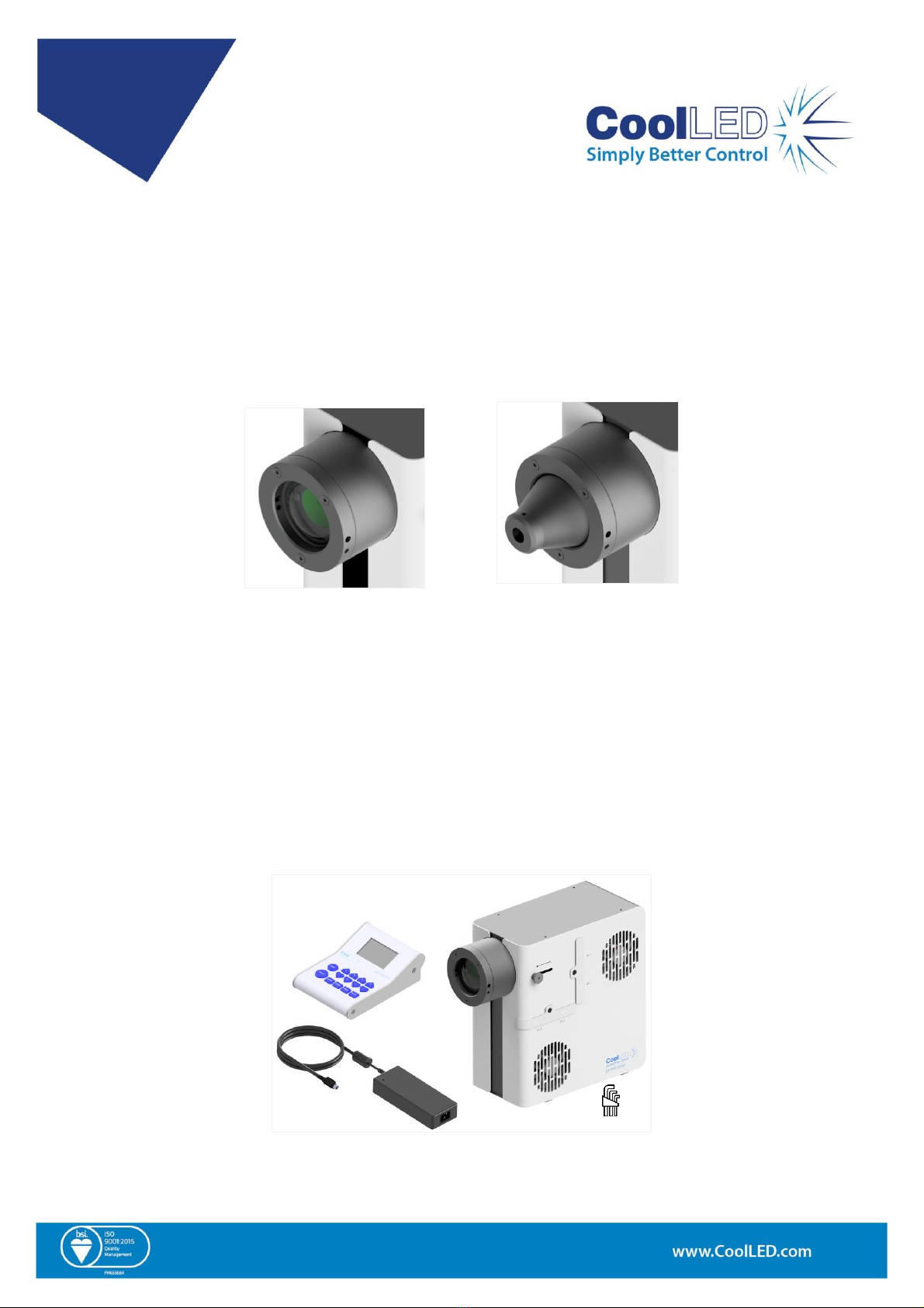
4. System Components ............................3
5. Reference Diagrams.............................4
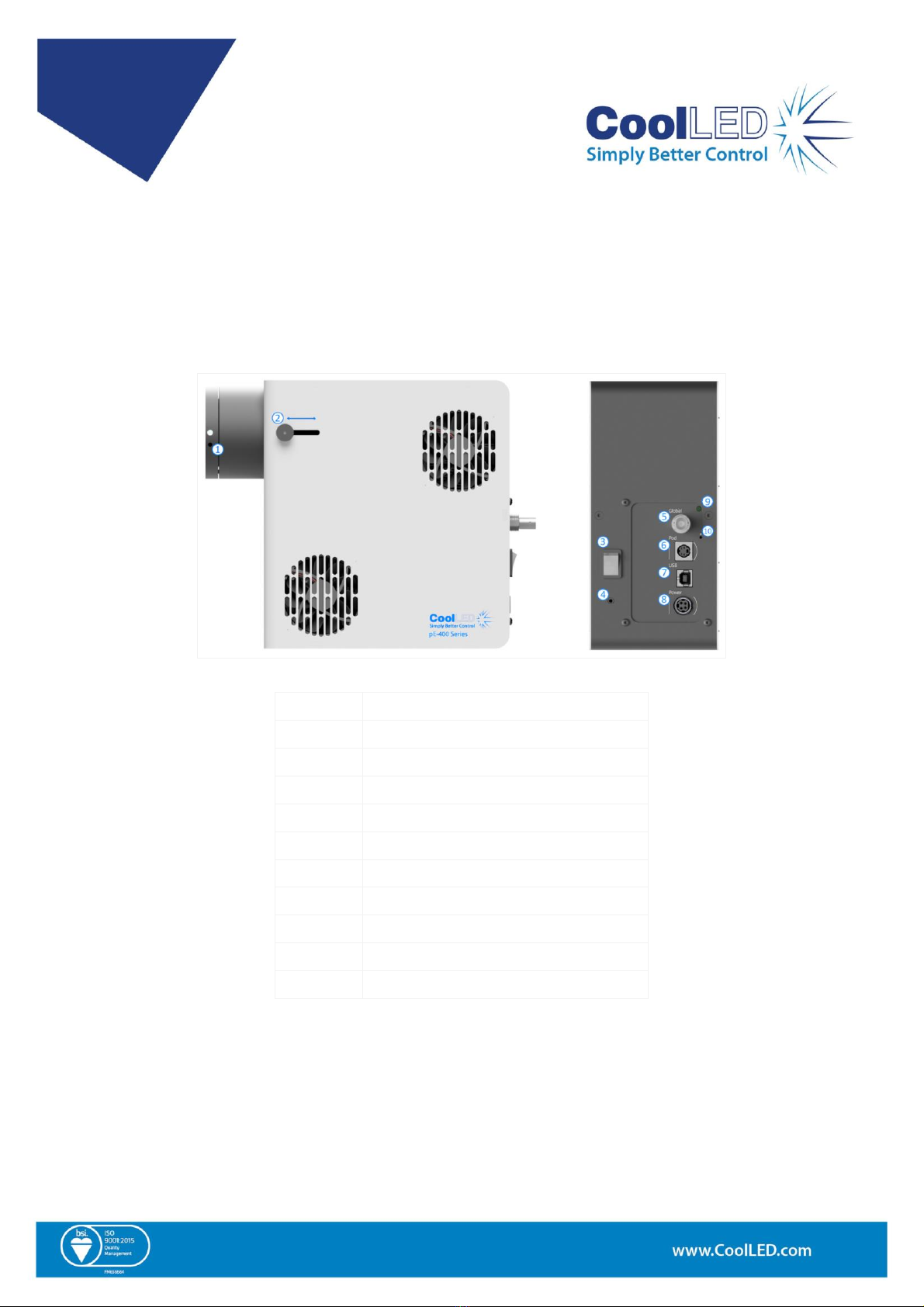
5.1. pE-400 Light Sources ........................4
5.2. pE-400max Light Sources....................7
6. Installation ....................................... 10
6.1 Mounting the Light Source ..............10
6.2. Electrical Connections ....................12
7. Light Source Control .......................... 13
7.1. Manual Control Pods ......................13
7.2. TTL Triggering.................................18
7.3. Software ........................................18
7.4. pE-400max LightBridge.....................18
7.5. Sequence Runner (pE-400max) .........21
8. Excitation Filters (pE-400max) .............. 24
8.1. Excitation Filter Installation............24
9. Optical Adjustment............................ 26
10. Product options and Order Codes ..... 27
11. Warranty and Repairs ...................... 27
12. Compliance ..................................... 28
WEEE ....................................................28
RoHS .....................................................28
13. Recycling......................................... 28
14. Contact Details ................................ 29
15. Product Specifications...................... 29
16. Appendix ........................................ 31
16.1. Boot Load Procedure ....................31

DOC-075 Iss 1 1
1. Introduction
Congratulations on the purchase of your new CoolLED pE-400 Series Illumination System.
The pE-400 Series is a family of state-of-the-art four-wavelength LED Illumination Systems
designed to meet the demands of cutting-edge microscopy applications.
This User Manual provides all the information required for installation and safe operation.
For additional details as well as other valuable LED illumination resources, please see the
CoolLED website: www.coolled.com.
2. Safety
Warning: While LEDs are much safer than the mercury and metal halide lamps they
replace, the following precautions must be taken when operating your pE-400 Series
Illumination System. Failure to do so may result in permanent injury, damage to
property or both.
•Only use the power supply and power cord provided to power the device.
•Never look directly into the output of the Light Source or attached accessories. The
light can permanently damage the eye and may lead to blindness.
•Always ensure the Light Source is securely attached to the microscope before
applying power to the device.
•If the Light Source must be operated while not attached to a microscope, all
personnel must wear appropriate eye shielding and protective clothing. CoolLED
strongly discourages using any CoolLED Light Source when not securely mounted to a
microscope.
Warning: Optical surfaces must only be cleaned with specifically designed optical
wipes and purpose-formulated optical cleaning solutions. Failure to use optics-
specific cleaning products may permanently damage the CoolLED Light Source.

DOC-075 Iss 1 2
3. pE-400 Series Product Range
3.1. Light Source Models
The pE-400 Series includes two models: the pE-400 and the pE-400max.
The pE-400 is a simple, cost-effective white light source and controllable replacement for
mercury and metal halide lamps.
The pE-400max permits the independent adjustment of channel irradiance and the ability to
fit inline excitation filters.
3.2. Wavelength Variants
The pE-400 and pE-400max can be purchased in two wavelength variations: Single-Band (SB)
and Multi-Band (MB). The graph and Table 1 below detail the wavelengths available in the
pE-400 Series and the respective channel number.
Wavelength
Variant
Channel 1
Wavelength
(nm)
Channel 2
Wavelength
(nm)
Channel 3
Wavelength
(nm)
Channel 4
Wavelength
(nm)
Single-Band
(SB)
365
450
550
635
Multi-Band
(MB)
400
450
550
635
Table 1

DOC-075 Iss 1 3
3.3. Light Delivery Variants
The pE-400 and pE-400max are available with Direct Fit (DF) and Liquid Light Guide (LLG)
output couplings. Direct Fit Light Sources (Figure 1) are designed to be secured directly to
the epi-illumination arm of compatible microscopes, while liquid light guide units (Figure
2) accommodate a 3 mm light guide. The attached liquid light guide can be used as an
input to an optional collimator or as a direct input to compatible microscopes.
Figure 1 –Direct Fit Output
Figure 2 –Liquid Light Guide
Output
4. System Components
pE-400 Series Illumination Systems include various components necessary to meet the
demands of specific microscope installations. At a minimum, the pE-400 Series
Illumination System includes the following:
•A pE-400 Series Light Source
•A pE-400 Series Control Pod
•A power supply
•A 1.5 mm Hex Key required for installation
Figure 3 –(Anti-Clockwise) A pE-400max Control Pod, a pE-400 Series Power Supply, 1.5 mm Hex Key
and pE-400max Light Source.
1.5 mm

DOC-075 Iss 1 4
5. Reference Diagrams
5.1. pE-400 Light Sources
Direct Fit
Figure 4
Item
Description
1
Adaptor retention screws
2
Focus adjustment
3
On/off switch
4
Grounding terminal
5
Global TTL input (global shutter)
6
Control Pod socket
7
USB A socket
8
Power socket
9
Status indicator
10
Bootload switch
Table 2

DOC-075 Iss 1 5
Liquid Light Guide
Figure 5
Item
Description
1
On/off switch
2
Grounding terminal
3
Global TTL input (global shutter)
4
Control Pod socket
5
USB A socket
6
Power socket
7
Status indicator
8
Bootload switch
9
Liquid light guide retention screws
Table 3

DOC-075 Iss 1 6
pE-400 Control Pod
Figure 6
Item
Button Description
1
Mode
2
On/off
3
Increase global irradiance
4
Decrease global irradiance
Table 4

DOC-075 Iss 1 7
5.2. pE-400max Light Sources
Direct Fit
Figure 7
Item
Description
1
Adaptor retention screws
2
Focus adjustment
3
Filter slot 1
4
Filter slot 2
5
On/off switch
6
Grounding terminal
7
Channel TTL input 365/400 nm (channel shutter)
8
Channel TTL input 450 nm (channel Shutter)
9
Channel TTL input 550 nm (channel Shutter)
10
Channel TTL input 635 nm (channel Shutter)
11
Global TTL input (global shutter)
12
Control Pod socket
13
USB A socket
14
Power socket
15
Status indicator
16
Bootload switch
Table 5

DOC-075 Iss 1 8
Liquid Light Guide
Figure 8
Item
Description
1
Filter slot 1
2
Filter slot 2
3
On/off switch
4
Grounding terminal
5
Channel TTL input 365/400 nm (channel shutter)
6
Channel TTL input 450 nm (channel shutter)
7
Channel TTL input 550 nm (channel shutter)
8
Channel TTL input 635 nm (channel shutter)
9
Global TTL input (global shutter)
10
Control Pod socket
11
USB A socket
12
Power socket
13
Status indicator
14
Bootload switch
15
Liquid light guide retention screws
Table 6

DOC-075 Iss 1 9
pE-400max Control Pod
Figure 9
Item
Button Description
1
Mode
2
On/off
3
Increase irradiance channel 1
4
Decrease irradiance channel 1
5
Select channel 1
6
Increase irradiance channel 2
7
Decrease irradiance channel 2
8
Select channel 2
9
Increase irradiance channel 3
10
Decrease irradiance channel 3
11
Select channel 3
12
Increase irradiance channel 4
13
Decrease irradiance channel 4
14
Select channel 4
Table 7

DOC-075 Iss 1 10
6. Installation
6.1 Mounting the Light Source
The procedure for mounting your pE-400 Series Light Source to a microscope depends on
the light delivery variant.
6.1.1. Direct Fit Light Sources
Attach the Light Sources directly to the epi-illumination port of the microscope using a
suitable CoolLED pE-Adaptor.
Note:
•The CoolLED adaptor is specified on ordering and will already be installed on your Light
Source. For instructions to swap adaptors, e.g., if fitting to a different microscope, please see
section 6.2.
•The exact method of attachment depends on the microscope configuration –please follow
microscope manufacturer’s instructions.
•The Light Source may be oriented horizontally or vertically to fit the microscope, provided
the air vents are not obstructed (Figure 10).
•Optical adjustment is required once installed. Please see Section 9. Optical Adjustment.
Figure 10 –A pE-400max Light Source fitted to a microscope in a horizontal orientation.

DOC-075 Iss 1 11
6.1.2. Moving to a Different Microscope
1. To establish which pE-Adaptor is required for your microscope, please visit
https://www.coolled.com/products/adaptors/.
2. Insert the pE-Adaptor into the output of the pE-400 Series Light Source (Figure 11).
3. Secure the pE-Adaptor in place by gently fastening the adaptor retention grubs screws
found at the output of the Direct Fit Light Sources. A 1.5 mm Hex Key is required to
drive the grub screws (Figure 12).
Figure 11
Figure 12
Warning: Do not over-tighten the adaptor retention grub screws. Over-tightening
may damage the pE-Adaptor or the Light Source and result in an unsafe or poorly
performing installation.
6.1.3. Liquid Light Guide Variants
Liquid Light Guide variants of the pE-400 Series accept a 3 mm liquid light guide.
1. Insert a free end of a 3 mm liquid light guide into the Light Source, ensuring that the
light guide is fully seated in the Light Source output barrel (Figure 13).
2. While holding the liquid light guide securely in place, use the 1.5 mm Hex Key to
gently fasten retention grub screw found at the output of the Light Source (Figure 14).

DOC-075 Iss 1 12
Figure 13
Figure 14
Warning: Do not over-tighten the adaptor retention grub screws. Over-tightening
may damage the liquid light guide or the Light Source and result in an unsafe or
poorly performing installation.
3. For microscopes that permit direct liquid light guide insertion, insert and secure the
free end as per the microscope manufacturer’s instructions.
For microscopes that do not permit direct liquid light guide insertion, the free end of
the liquid light guide must be fed into a collimator such as the CoolLED pE-Universal
Collimator. For information on installation, optical adjustment and moving to a
different microscope, please see: https://www.coolled.com/products/accessories/pe-
uv-universal-collimator/).
6.2. Electrical Connections
With the pE-400 Series Light Source installed in its final location, the Control Pod and
Power Supply must be connected to the Light Source using the following steps.
1. Ensure the on/off switch on the back panel of the Light Source is in the off position.
2. Connect the Control Pod to the Light Source by inserting the Control Pod connector
into the pod socket marked on the back panel of the Light Source. Use the markings
surrounding the pod socket for correct orientation.
3. Connect the Power Supply to the Light Source by inserting the Power Supply
connector into the power socket marked on the back panel of the Light Source. Use
the markings surrounding the power socket for correct orientation.

DOC-075 Iss 1 13
Figure 15 –pE-400max Light Source back panel showing the On/Off Switch (left), and pod socket and power
sockets with surrounding markings to guide orientation of connectors (right).
7. Light Source Control
With the pE-400 Series Light Source installed and connections made, the following steps
initiate and modulate illumination. The steps required depend on whether your Light
Source is a pE-400 (with global irradiance control) or a pE-400max with individual channel
irradiance control.
7.1. Manual Control Pods
7.1.1. pE-400: Initiating Illumination
1
Power up your pE-400 Light Source by switching the on/off switch on the back panel of
the Light Source to the on position.
2
Observe the Control Pod booting up.
Figure 16 shows the Control Pod screen
once the boot sequence has concluded.
Figure 16

DOC-075 Iss 1 14
3
Use the increase global irradiance button
(+) and decrease global irradiance button
(-) to input the desired irradiance. The
Light Source output is off (extinguished)
during this adjustment period1, indicated
by the OFF text and striped irradiance bar
on the Control Pod.
Figure 17
4
Press the on/off button once to switch
the Light Source output on (illuminated).
The ON text and solid irradiance bar on
the Control Pod indicate the on state.
Figure 18
5
Press the on/off button again to extinguish the Light Source.
7.1.2. pE-400: Display Backlight and Contrast Settings
Adjusting the LCD backlight and contrast settings allows the Control Pod to remain legible
but unobtrusive across ambient lighting conditions.
1
Press the mode button for 3 seconds to
access the Backlight settings.
Figure 19
2
Use the increase global irradiance button
(+) and decrease global irradiance button
(-) to adjust the Backlight.
3
Press the mode button to access the
Contrast settings.

DOC-075 Iss 1 15
4
Use the increase global irradiance button
(+) and decrease global irradiance button (-
) to adjust the Contrast.
Figure 20
5
To return to the main screen, either press
and hold the mode button for 3 seconds
or wait for 10 seconds and the screen will
return automatically.
7.1.3. pE-400max: Initiating Illumination
1
Power up your pE-400max Light Source by switching the on/off switch on the back panel
of the Light Source to the on position.
2
Observe the Control Pod booting up.
Figure 21 shows the Control Pod screen
once the boot sequence has concluded.
Figure 21
3
Select the channel (or channels) to be illuminated using the select button appropriate
for the desired channel.
4
Use the increase irradiance buttons (+) and decrease irradiance buttons (-) for a
channel to input the desired irradiance.
5
A striped power bar on display indicates
any selected channel with an irradiance
value greater than zero. The Light Source
output is off (extinguished) during this
adjustment period, indicated by the OFF.1
Figure 22
1
The irradiance of the Light Source can be adjusted when the Light Source is either in an on or an
off state. If the output is on, changes in irradiance are immediately visible through the microscope
eyepiece.

DOC-075 Iss 1 16
6
Press the on/off button once to switch
the Light Source output on (illuminated)
for all selected channels. The ON text and
solid irradiance bar on the Control Pod
indicate the on state.
Figure 23
7
Press the on/off Button again to extinguish the Light Source.
7.1.4. pE-400max: Display Backlight and Contrast Settings
Adjusting the LCD backlight and contrast settings allows the Control Pod to remain legible
but unobtrusive across ambient lighting conditions.
1
Press the mode button for 3 seconds to
reveal the Settings screen.
Figure 24
2
Use the increase irradiance button (+)
and decrease irradiance button (-) below
the Back (Backlight) and Cont (Contrast)
columns to increase and decrease the
associated settings.
3
To return to the main screen, either press
and hold the mode button for 3 seconds
or wait for 10 seconds and the screen will
return automatically.
7.1.5 pE-400 and pE-400max System Information
To access information relating to hardware, software, run-time and diagnostic data, take
the following steps:
1
Press and hold the mode button for 3 seconds.
2
Once the display settings screen appears (see 7.1.2. pE-400: Display Backlight and
Contrast Settings), press the mode button repeatedly to cycle through the available
resources.

DOC-075 Iss 1 17
3
pE-400max firmware and hardware
information.
Figure 25
4
pE-400 firmware and hardware
information.
Figure 26
5
Channel and system runtime
information.
Figure 27
6
Channel diagnostic information.
Figure 28
7
To return to the main screen, either
press and hold the mode button for 3
seconds or wait for 10 seconds and the
screen will return automatically.

DOC-075 Iss 1 18
7.2. TTL Triggering
7.2.1 Global Triggering
All pE-400 Series Light Sources include a Global TTL Input (see Reference Diagrams in
section 5 ). This provides the facility to control the overall illumination state of the Light
Source using a TTL-output from a device such as a camera.
Inputting 5 V (high) into the Global TTL Input illuminates all the selected channels, while 0
V (low) extinguishes all channels. Channels can be selected using either the Control Pod,
LightBridge or third-party software.
7.2.2. Channel Triggering (pE-400max)
pE-400max Light Sources include Channel TTL Inputs (see Reference Diagrams in section 5.2.
pE-400max Light Sources), which provide the facility to control the illumination state of the
individual channels.
Channel TTL inputs operate similarly to the channel selection buttons on the pE-400max
Control Pod. When a 5 V (high) trigger is received by the Channel TTL Input, this effectively
selects the associated channel in the same way that pressing a selection button does.
Receiving 0 V (low) effectively deselects the associated channels.
If a TTL high is present on a Channel TTL Input, the associated Light Source Channel will
illuminate.
7.3. Software
The pE-400 and pE-400max have USB connectivity for control through imaging software. For
more information and to see which third-party software platforms support the pE-400
Series, please visit: https://www.coolled.com/support/imaging-software/.
7.4. pE-400max LightBridge
pE-400max LightBridge is a Windows PC application developed by CoolLED. The application
controls pE-400max Light Sources and is not compatible with any other CoolLED Light
Sources.
LightBridge shares many of the control features found on the pE-400max Control Pod (for
example, irradiance control and channel selection) but adds advanced configuration
options like boot control.
The application’s integration with the pE-400max Control Pad is seamless. Any Light Source
adjustments made using the Control Pod are immediately reflected in the application;
likewise, adjustments made using LightBridge reflect immediately on the attached pE-
400max Control Pod.
Other manuals for pE-400 Series
1
This manual suits for next models
2
Table of contents
Other CoolLED Laboratory Equipment manuals
Popular Laboratory Equipment manuals by other brands

cytiva
cytiva ReadyToProcess 600 operating instructions

Labnet
Labnet ProBlot 6 instruction manual

Agilent Technologies
Agilent Technologies 7890 Series Troubleshooting

Cole Parmer
Cole Parmer CG-500 quick start guide

Tektronix
Tektronix WVR610A Service manual

Izon
Izon AUTOMATIC FRACTION COLLECTOR V1 quick start guide