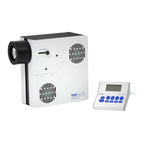
CoolLED pE-800 User manual

DOC-058 Iss 3 1
User Manual
pE-800
8-channel LED illumination

DOC-058 Iss 3 2
Contents
1. Introduction ............................................................................................. 3
2. Safety Precautions ................................................................................... 3
3. Getting Started –System Components.................................................... 6
4. Installation and Setup .............................................................................. 7
5. pE-800 LEDs overview............................................................................ 10
6. Control Overview ................................................................................... 11
7. LightBridge –Standard/TTL mode ......................................................... 15
8. LightBridge –Analogue Mode................................................................ 18
9. LightBridge –Sequence Runner Mode .................................................. 19
10. LightBridge –Demo Mode ..................................................................... 23
11. LightBridge –Additional settings ........................................................... 28
12. Fitting Excitation Filters.......................................................................... 37
13. Software updates................................................................................... 41
14. Additional information........................................................................... 44
15. Product Specifications............................................................................ 45
16. Product Options and Order Codes......................................................... 45
17. Warranty and Repairs ............................................................................ 46
18. Compliance and Environmental............................................................. 46
19.Contact Details....................................................................................... 47
20. Appendix 1 ............................................................................................. 48

DOC-058 Iss 3 3
1. Introduction
This manual should give you all the information required to install and
operate your new light source.
Additional information can be found on our website at www.coolled.com.
2. Safety Precautions
While LEDs are a much safer illumination system than the mercury and
metal halide lamps that they replace in microscopy applications, precautions
should still be taken with this product.
When operating or maintaining this product, please observe the following
safety precautions at all times. Failure to do so may result in personal injury
or damage to other items.
Please ensure that only the power supply and cord supplied are used with
this equipment.
The AC cord supplied with this Light Source must only be used with the
equipment supplied.
2.1.
UV light may be emitted from this product depending on the
version/wavelength selected. Avoid eye and skin exposure. Never look
directly into the light output beam from the Light Source or accessories. The
emissions could damage the cornea and retina of the eye if the light is
observed directly.
2.2.
Always ensure that the Light Source is securely attached to the microscope
(either directly or with a liquid light guide and collimator, depending on the
version) prior to turning on the power. This will minimise the risk of injury
and damage.
2.3.
If for any reason the Light Source is to be operated when not attached to a
microscope, all personnel should wear eye shielding and clothing to protect
the exposed skin.

DOC-058 Iss 3 4
2.4.
Disconnecting the mains supply is achieved by unplugging the power cord
from the power supply block or the Light Source. Only plug in the power
cable, once the Light Source is attached to the microscope.
2.5.
There are no serviceable parts within the Light Source. Removing any of the
screws and covers will result in the safety of the Light Source being impaired.
The DC power supply unit should be inspected periodically throughout the
lifetime of the system.
2.6.
Any electronic equipment connected to this product must comply with the
requirements EN/IEC 60950.
2.7.
To clean the exterior of the Light Source, use a slightly dampened cloth with
a simple water/detergent solution only. Avoid the optical surfaces and
lenses. Cleaning of optics should only be carried out using optical wipes and
fluids. Please note that the DC power supply unit should be isolated prior to
cleaning.
2.8.
This product conforms to the requirements of the Safety Standards as
follows:
EN/IEC 61010-1:2010 Safety requirements for Electrical Equipment for
Measurement, Control and Laboratory use.
EN62471:2008 Photo-biological Safety of Lamps and Lamp
Systems/ Guidance on manufacturing
requirements relating to non-laser optical
radiation safety. Risk Group 3.
All warnings may not be applicable depending on the version/wavelength being used.

DOC-058 Iss 3 5
2.9. EMC compliance
This product is tested to the requirements of standard IEC/EN 61326-1
concerning electromagnetic compatibility. This is a Class A product. In a
domestic environment this product may cause radio interference in which
case the user may be required to take adequate measures.

DOC-058 Iss 3 6
3. Getting Started –System Components
The CoolLED pE-800 Light Source is supplied with the following components:
•Main Light Source with Optical Output for 3 mm liquid light guide.
•DC Power Supply type GST160A12-R7B.
•IEC Power Cable.
•USB Cable.
•User Guide (USB stick).
•A variety of Hex keys.
In addition to the components listed above, it is possible that a liquid light
guide, collimator or additional accessories will be supplied.
When un-packing the system, it is important to check the contents against
the delivery note.
If any components are missing or appear damaged, please contact CoolLED
or the reseller who supplied the equipment immediately.

DOC-058 Iss 3 7
4. Installation and Setup
4.1.
Carefully unpack the components from the shipping material.
4.2.
Insert the power connector from the DC power supply as shown, with the
flat of the connector body facing up. At this stage do not connect the mains
power lead to the DC power supply.

DOC-058 Iss 3 8
4.3.
Insert the liquid light guide into the light output port of the Light Source.
Ensure that the end of the liquid light guide is fully inserted and gently
tighten the grub screw to retain it in position.
4.4.
Ensure that there is free airflow around the Light Source so that the cooling
system is not impaired. A gap of 100 mm around the light source is
sufficient. For optimal cooling performance the Light Source should only be
operated in the orientation shown throughout this document, stood on its
four rubber feet.
4.5.
Connect the second end of the liquid light guide into the desired microscope
using the required coupling mechanism. If using the pE-Universal Collimator,
refer to the dedicated User Manual for correct installation
(www.coolled.com/products/accessories/pe-universal-collimator/).

DOC-058 Iss 3 9
4.6.
With the liquid light guide fitted between the Light Source and the
microscope, it is now safe to connect the mains power. Connect the mains
lead supplied to a convenient socket, plug the IEC connector into the DC
power supply and switch the power on at the mains. The pE-800 can now be
switched on using the rocker switch shown in the below image.

DOC-058 Iss 3 10
5. pE-800 LEDs overview
5.1.
The pE-800 is an eight-channel Illumination System, with each of the eight
channels covering a distinct spectral region to suit use with common
fluorophores and their relevant filter sets, from DAPI in the UV to Cy7 in the
near infra-red. Each channel is individually controllable, allowing only the
required LEDs to be illuminated and the irradiance of these to be adjusted to
provide the desired signal.
5.2. Variants
In order to deliver the best performance with the wide range of available
filter sets, it is necessary to have two variants of the pE-800.
The “SB” variant which has an LED peaking at 365 nm in the UV region and
the “MB” variant which has an LED peaking at 400 nm in the Violet region
allow for optimal excitation of DAPI.
All other installed LEDs remain the same across the two variants.

DOC-058 Iss 3 11
6. Control Overview
6.1. Communication requirements
To communicate with the pE-800 a connection needs to be made between
the PC and Light Source. A USB A-male to B-male cable will have been
provided with the System. Connect the USB A connector into a free port on
the PC and connect the USB B connector into the USB socket on the Light
Source side panel (next to the power input). Please note the correct
orientation of this connector, with the top-side of the cable housing facing
up.
The interface is a ‘virtual COM port’ style and a setup procedure may be
necessary to enable communication between a PC and the Light Source. See
Appendix 1 for more details.
6.2. CoolLED LightBridge
To allow control of the pE-800, CoolLED has developed a graphical user
interface called the LightBridge.
The LightBridge software can be downloaded either from the User Guide
(USB stick) that is provided with the pE-800 or from the CoolLED website
(www.coolled.com/support/imaging-software/).
Details of the operation of the LightBridge can be found in the relevant
section of this User Manual.
Communication with the LightBridge is achieved through a USB connection.

DOC-058 Iss 3 12
6.3. Third party Imaging Software
The pE-800 can be operated under a range of popular imaging software
packages. Details of specific packages can be found on the CoolLED website
(www.coolled.com/support/imaging-software/).
6.4. TTL
The pE-800 can be controlled directly by TTL signals to control the ON/OFF
state of the Light Source. To define the LED irradiance or to set a sequence,
the TTL signals will need to be applied in combination with communication
from the LightBridge application.
Details of the voltage requirements and the switching performance are
shown in the graph below.
< 7 µs
< 3 µs

DOC-058 Iss 3 13
The details of the physical TTL connections for the pE-800 are shown below.
TTL Port
15 Position D-Sub, High Density Receptacle, Female Sockets Connector
Pin #
Name
Type
Maximum Rate Input/Output
Voltages
1
635 nm
Digital Input
0 ≤ Vin ≤ 5.5 V
2
550 nm
Digital Input
0 ≤ Vin ≤ 5.5 V
3
470 nm
Digital Input
0 ≤ Vin ≤ 5.5 V
4
TTL OUT 2
Digital
Output
0 ≤ Vout ≤ 3.3 V (typ)
0.4 (max) ≤ Vout ≤ 2.9 V(min)
5
GLOBAL TTL
Digital Input
0 ≤ V in ≤ 5.5 V
6
GROUND
Power
-
7
GROUND
Power
-
8
GROUND
Power
-
9
TTL OUT 1
Digital
Output
0 ≤ Vout ≤ 3.3 V (typ)
0.4(max) ≤ Vout ≤ 2.9 V(min)
10
GROUND
Power
-
11
500 nm
Digital Input
0 ≤ Vin ≤ 5.5 V
12
435 nm
Digital Input
0 ≤ Vin ≤ 5.5 V
13
365 nm
Digital Input
0 ≤ Vin ≤ 5.5 V
14
740 nm
Digital Input
0 ≤ Vin ≤ 5.5 V
15
580 nm
Digital Input
0 ≤ Vin ≤ 5.5 V
Global Input
BNC Connector Jack, Female Socket 50Ω
Pin
#
Name
Type
Maximum Rate Input/Output
Voltages
1
GLOBAL TTL
Digital Input
0 ≤ Vin ≤ 5.5 V

DOC-058 Iss 3 14
6.5. Analogue
The irradiance of the LEDs in the pE-800 can be set by applying an Analogue
Voltage to the relevant connections. A signal of 0-10 V can be applied to the
Analogue inputs and relates to 0-100 % irradiance. For example, a 6.5 V
signal applied to an input will set the channel to 65 % irradiance.
The details of the physical Analogue connections for the pE-800 are shown
below.
Analogue Port
15 Position D-Sub, High Density Receptacle, Female Sockets Connector
Pin #
Name
Type
Maximum Rate Input/Output Voltages
1
635 nm
Analogue Input
0 ≤ Vin ≤ 10 V
2
550 nm
Analogue Input
0 ≤ Vin ≤ 5.5 V
3
470 nm
Analogue Input
0 ≤ Vin ≤ 5.5 V
4
ANALOGUE OUT 2
Analogue
Output
0 ≤ Vout ≤ 10 V
5
INTERLOCK
Digital Input
0 ≤ Vin ≤ 5.5 V
6
ANALOGUE
GROUND
Power
-
7
ANALOGUE
GROUND
Power
-
8
ANALOGUE
GROUND
Power
-
9
ANALOGUE OUT 1
Analogue
Output
0 ≤ Vout ≤ 10 V
10
GROUND
Power
-
11
500 nm
Digital Input
0 ≤ Vin ≤ 5.5 V
12
435 nm
Digital Input
0 ≤ Vin ≤ 5.5 V
13
365 nm
Digital Input
0 ≤ Vin ≤ 5.5 V
14
740 nm
Digital Input
0 ≤ Vin ≤ 5.5 V
15
580 nm
Digital Input
0 ≤ Vin ≤ 5.5 V

DOC-058 Iss 3 15
7. LightBridge –Standard/TTL mode
7.1.
When the CoolLED LightBridge is opened the below display will be shown (if
the pE-800 is not switched on). The status will be shown in the bottom right
corner as Offline.
7.2.
Once the power switch of the Light Source is turned on and the System is
connected to the PC with a USB cable, the LightBridge will detect the
presence of the Light Source and show the status as “Online”. At this point
the installed LEDs listed at the top of the display will be updated to reflect
whether an SB or MB version of the pE-800 is being used.

DOC-058 Iss 3 16
7.3.
The irradiance of each of the eight channels can be adjusted by either
clicking and moving the slider with your mouse, typing the irradiance figure
in the text box or adjusting the irradiance using the arrows.
7.4.
Checking the box below the irradiance figure will put that channel into a
selected state.

DOC-058 Iss 3 17
7.5.
Pressing the On/Off button in the bottom left corner of the display will cause
all wavelengths in the selected state to illuminate at their defined irradiance.

DOC-058 Iss 3 18
8. LightBridge –Analogue Mode
Checking the Analogue mode box removes the ability to control the On/Off
status and the channel irradiance through the LightBridge. The pE-800
irradiance level will now be controllable from a voltage between 0-10 V to
the relevant Analogue input pin. The On/Off state of the Light Source will be
controllable with a TTL signal. This could either be to the global TTL pin (all
channels with an Analogue signal applied will illuminate with a TTL high). It
could instead be to the dedicated channel TTL inputs (the dedicated channel
will illuminate if an Analogue signal is applied to the corresponding channel
that also has a TTL high applied).

DOC-058 Iss 3 19
9. LightBridge –Sequence Runner Mode
9.1.
To access Sequence Runner Mode click on the dropdown tab at the top of
the page that is labelled “Standard/TTL” under normal operating conditions.
Select “Sequence” from the dropdown list.
9.2.
Once “Sequence Runner Mode” is selected the following display will be
shown. All channels will be set to the off state at 0 % irradiance.

DOC-058 Iss 3 20
9.3.
Define the triggering order by checking the boxes of the required channels in
the order you would like them to illuminate. The first box checked will select
the first channel of a triggering sequence, the second box will select the
second channel and so on. This will be shown by a number appearing next to
the check box to show this order. The irradiance will also need to be set
using either the slider, arrows or text boxes for each required channel.
9.4.
To activate the sequence, click the “Ready” button.
Other manuals for pE-800
4
Table of contents
Other CoolLED Laboratory Equipment manuals
Popular Laboratory Equipment manuals by other brands

Promega
Promega Maxwell 16 AS1000 operating manual

OHAUS
OHAUS STDO21 General instructions

Cole Parmer
Cole Parmer HO-400 Series user manual

Biosan
Biosan Automatic Luminescence Analyser ALA1/4 operating manual

Labnet
Labnet Spectrafuge 16M user manual

Pasco Scientific
Pasco Scientific TD-8579A Instruction manual and experiment guide