Solar Combiner Solutions - CCB Series
Installation & Maintenance Information
SAVE THESE INSTRUCTIONS FOR FUTURE REFERENCE
IF 1598
IF 1598 • 12/10 Copyright © 2010, Cooper Industries, Inc. Page 1
SAVE THESE INSTRUCTIONS - This manual contains important instructions for Solar
Combiner Boxes that shall be followed during installation and maintenance for the
CCB Series.
1.0 OVERVIEW
Cover all modules in the PV array with dark, opaque material before making
electrical connections to the combiner box from the panels. All U.S. installations
must be performed in compliance with the National Electrical Code (NEC),
ANSI/NFPA 70 and applicable local codes. Cooper Crouse-Hinds Combiner Boxes
comply with the National Electrical Code.
All Canadian installations shall conform to Canadian Electrical Code Part I.
Installation should be performed only by authorized personnel.
The combiner boxes comply with UL1741 safety listing for continuous rated
current operation at 50°C.
2.0 INTRODUCTION
(PLEASE SAVE THESE INSTRUCTIONS)
This manual provides important instructions for the Cooper Crouse-Hinds (CCH)
Combiner Boxes and shall be followed during installation and maintenance. The
CCH Combiner Boxes are designed and tested to stringent safety requirements.
However, as with all electrical equipment, specific safety practices must be
followed. To reduce the risk of injury, carefully read this instruction booklet in its
entirety before installing, wiring, or using this product in any way.
2.1. DISCLAIMER OF LIABILITY
The installation techniques, handling and use of this product are beyond company
control. Therefore, Cooper Crouse-Hinds does not assume responsibility for loss,
damage or expense resulting from improper installation, handling or use of this
product.
2.2. LISTING INFORMATION
This product meets or exceeds the requirements set forth by Underwriters
Laboratories (UL) for components used with PV Modules. This UL Standard is
UL1741 for accessories used with inverters.
2.3. LIMITED WARRANTY
Combiner box limited warranties are for 1 year for materials and workmanship.
3.0 IMPORTANT SAFETY INSTRUCTIONS
There are no user-serviceable parts in this enclosure, other than the fuses. Do
not alter any portion of this product; otherwise, the warranty will be invalidated.
Storage temperature: - 60ºC to +85ºC
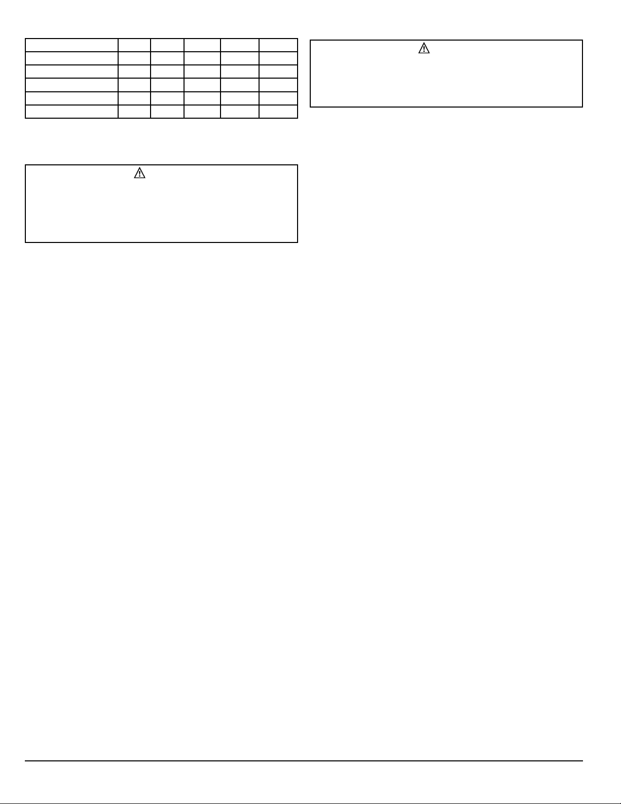
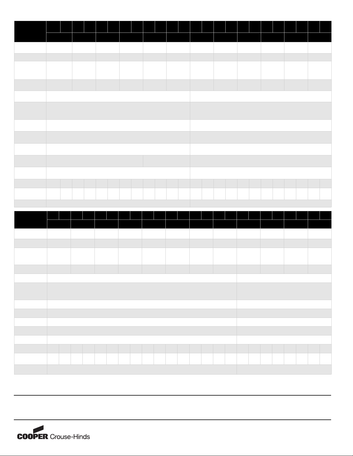
4.0 ELECTRICAL CHARACTERISTICS
The combiner box electrical ratings are indicated on Table 2, see page 4.
5.0 COMBINER BOX MOUNTING
VENTILATION CONSIDERATION
Maintain a minimum clearance of 1” on all 4 sides of the enclosure.
Install the enclosure using the 4 external enclosure mounting tabs only. Drilling
holes in the back plate is not recommended and shall void the product warranty.
Place in desired location on a sturdy frame and use the appropriate hardware to
mount the combiner box.
The steel combiner box may be mounted vertically (door opens out) only. The
fiberglass combiner box may be mounted both horizontally and vertically.
Place the box in areas out of continuous water flow and extreme temperature.
6.0 CONDUIT ROUTING
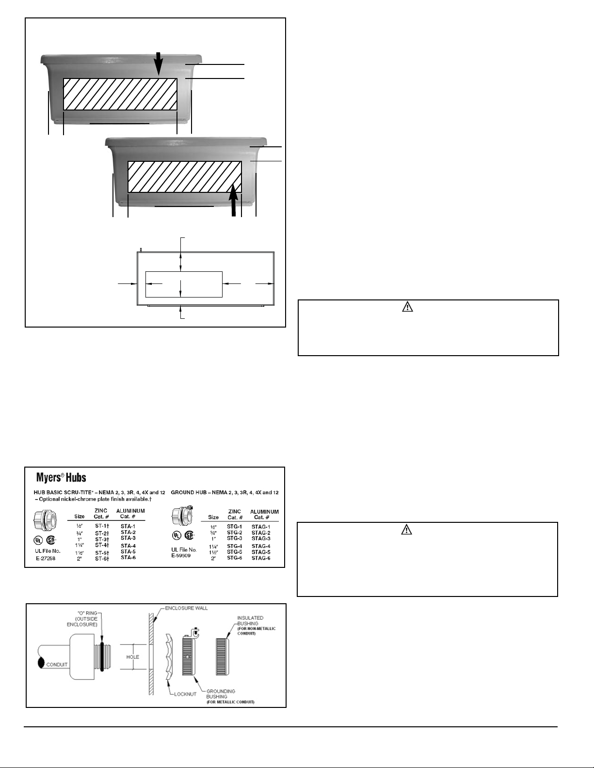
6.1. CONDUIT HOLES
Please refer to Figure 1 for conduit entry areas on the enclosure for all models.
Cut conduit holes in the desired location. The preferred method is the use of a
Greenlee®cutter of the appropriate size. The punch of the cutter should be
placed on the inside of the enclosure and drawn to the outside. Remove all
shavings and debris from enclosure.
6.2. CONNECTOR TYPE
The use of UL514B or equivalent conduit fittings is required to maintain the
environmental rating of the enclosure. Installation of fittings must comply with
UL50 for USA installations and CSA C22.2 No. 94 for Canadian installations to
maintain rating of the enclosure. See Figure 2 for suitable connectors. For use
with rigid/IMC conduit use of Cooper Crouse-Hinds Myers™conduit hub is
recommended. For non-metallic liquidtight conduit, Cooper Crouse-Hinds Lt-NM
series connector is recommended.
WARNING
To avoid the risk of fire or electric shock, this product should be installed, inspected,
and maintained by a qualified electrician only, in accordance with all electrical codes.
IMPORTANT SAFETY INSTRUCTION
WARNING
PV modules produce direct current (DC) when the module is under load. Direct current
will arc across gaps and may cause injury or death if improper connection or
disconnection is made. Do not connect or disconnect wires to the combiner box when
current from the modules or an external source is present.
WARNING
Use insulated tools to reduce your risk of electric shock. Do not install or handle the
combiner box if it is wet. Contact Cooper Crouse-Hinds at
contents are compromised.
WARNING
To avoid the risk of electric shock, remove all metallic jewelry prior to installing this
product to reduce the chance of accidental exposure to live circuits.