Cooper Crouse-Hinds GmbH
88
88
8
9 Entsorgung / Wiederver-
wertung
Bei der Entsorgung des Betriebsmittels sind
die jeweils geltenden nationalen Abfall-
beseitigungsvorschriften zu beachten.
Zur Erleichterung der Wiederverwertbarkeit
von Einzelteilen sind Kunststoffteile mit dem
Kennzeichen des verwendeten Kunststoffes
versehen.
Programmänderungen und -ergänzungen sind
vorbehalten.
8 Reparatur / Instandsetzung /
Änderungen
Instandsetzungsarbeiten / Reparaturen dürfen
nur mit CCH / CEAG Originalersatzteilen
vorgenommen werden.
Bei Schäden an der druckfesten Kapselung
ist nur ein Austausch zulässig. Im Zweifels-
falle ist das betroffene Betriebsmittel an
CCH / CEAG zur Reparatur zurückzuge-
ben.
Reparaturen, die den Explosionsschutz
betreffen, dürfen nur von CCH / CEAG
oder einer qualifizierten Elektrofachkraft
in Übereinstimmung mit national gelten-
den Regeln durchgeführt werden.
Umbauten oder Änderungen am Betriebsmit-
tel sind nicht gestattet; ausgenommen ist das
Anbringen von zusätzlichen KLE's im Rahmen
der Zulassung des Betriebsmittels.
6.6 Inbetriebnahme
Vor Inbetriebnahme des Betriebsmittels sind
die in den einzelnen nationalen Bestimmungen
genannten Prüfungen durchzuführen.
Ausserdem ist vor der Inbetriebnahme die
korrekte Funktion und Installation des
Betriebsmittels in Übereinstimmung mit
dieser Betriebsanleitung und anderen
anwendbaren Bestimmungen zu überprüfen.
Unsachgemäßer Betrieb der Sicherheits-
schalter kann zum Verlust der Garantie
führen.
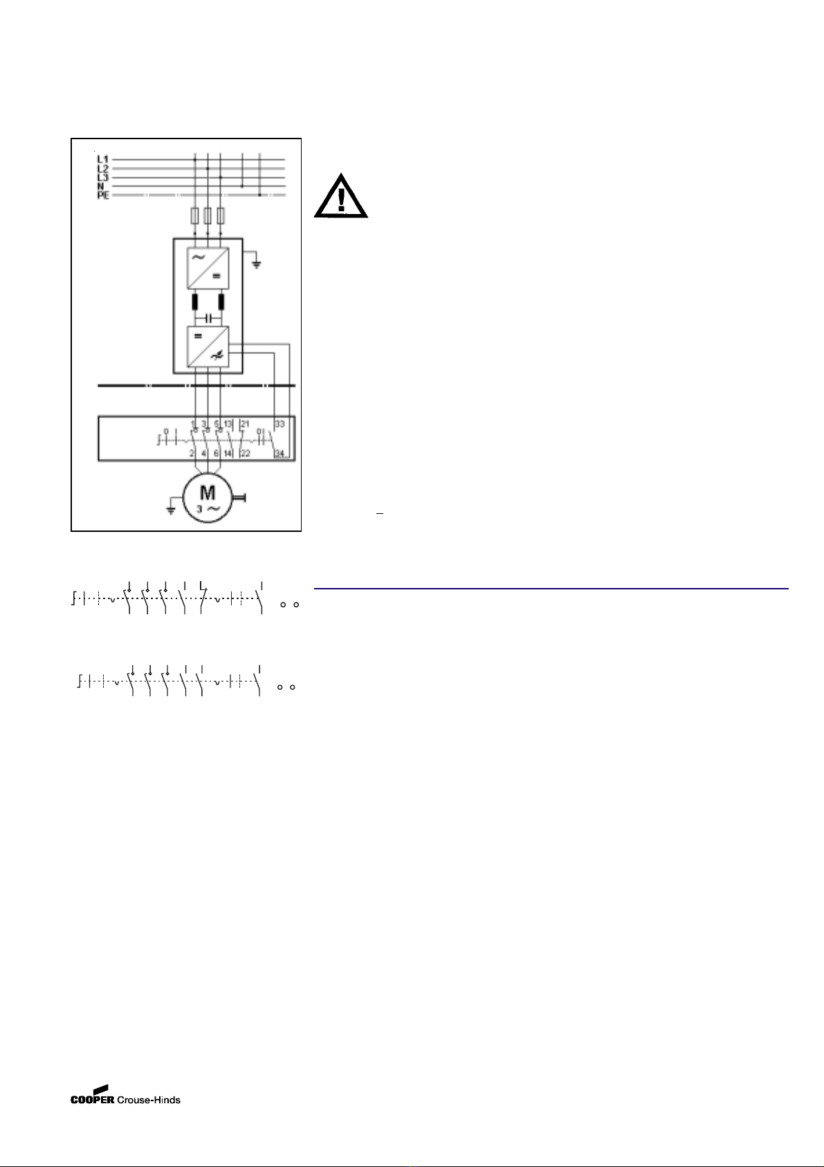
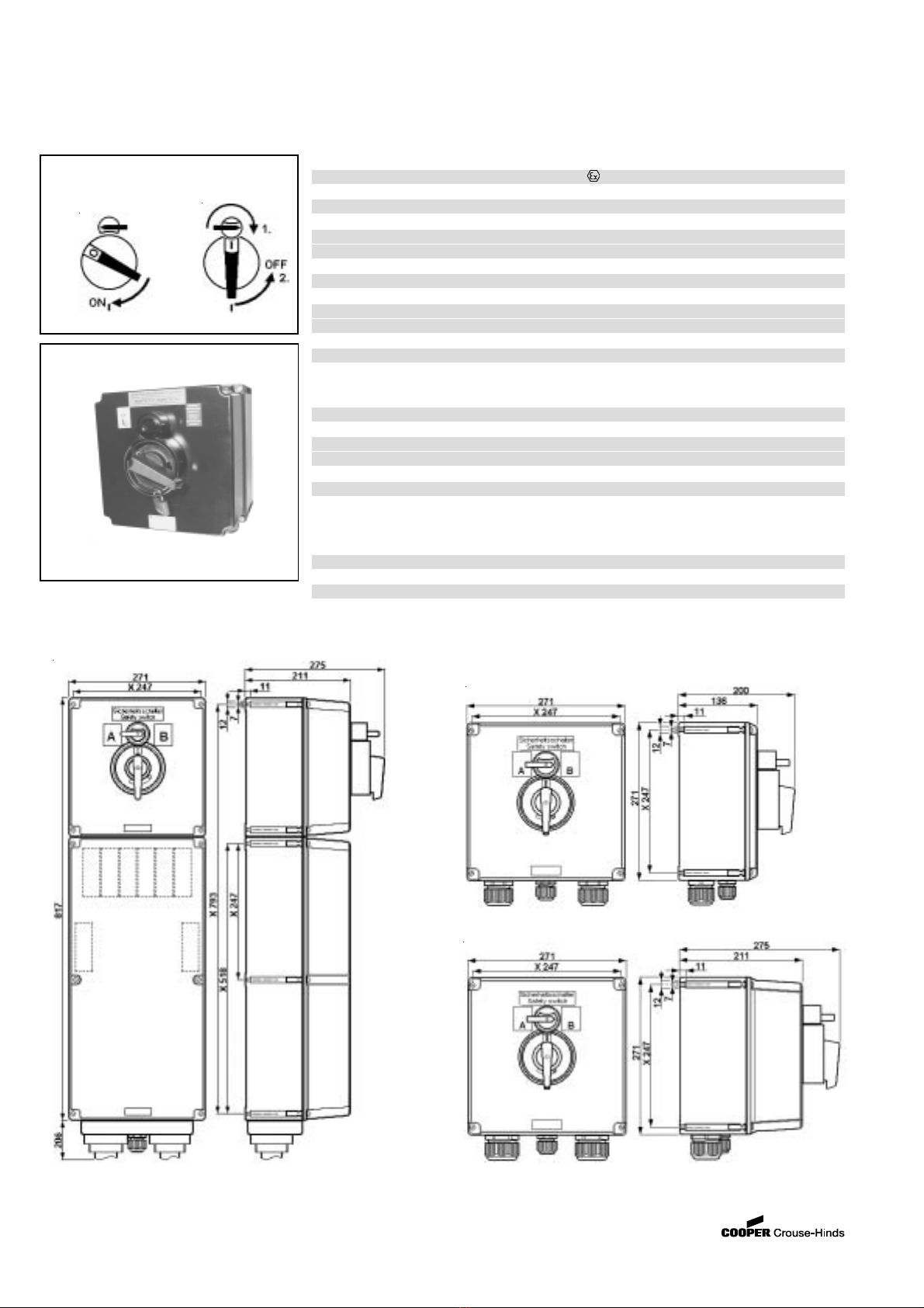
Explosionsgeschützte Sicherheitsschalter für geregelte
Drehstromantriebe, 20A - 180A
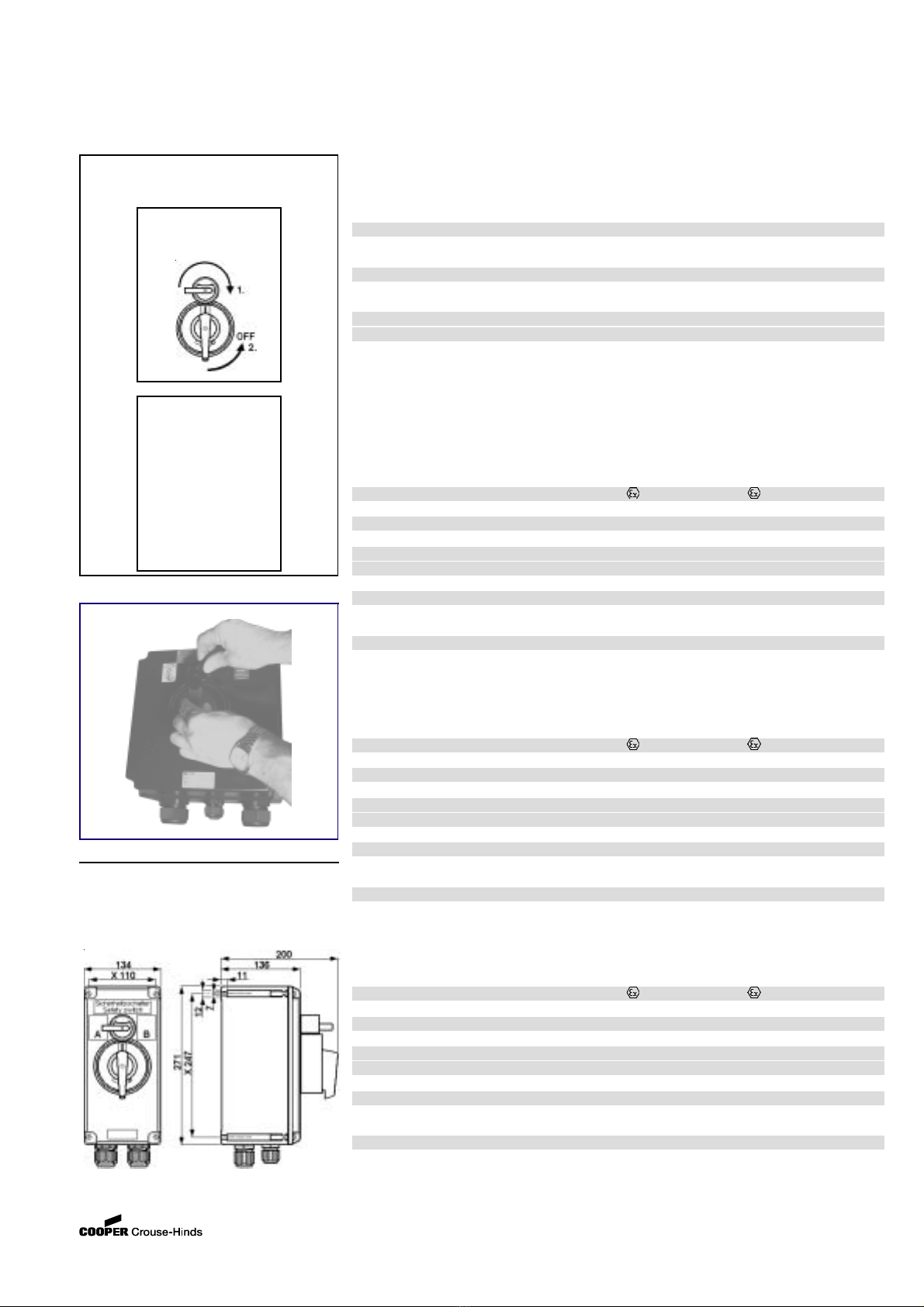
6.5 Schließen des Gerätes
Alle Fremdkörper sind aus dem Gerät zu
entfernen.
Der Schaltgriff am Deckel der Sicherheits-
schalter muss in "EIN"-Stellung stehen.
Beim Aufsetzen des Gehäusedeckels ist
darauf zu achten, dass die Schaltachse des
Schalteinsatzes korrekt in die Mitnehmer-
öffnung des Schaltgriffes eingeführt wird.
Zur Sicherstellung der erforderlichen Mindest-
schutzart sind die Deckelschrauben fest
anzuziehen.
Bei übermäßigem Anziehen kann die
Schutzart beeinträchtigt werden.
7 Instandhaltung / Wartung
Die für die Wartung / Instandhaltung von
elektrischen Betriebsmitteln in explosions-
gefährdeten Bereichen geltenden nationa-
len Bestimmungen sind einzuhalten (z.B.
ElexV, VDE 0105 Teil 9 in Deutschland).
Vor Öffnen des Gehäuses Spannungs-
freiheit sicherstellen oder geeignete
Schutzmaßnahmen ergreifen.
Die erforderlichen Wartungsintervalle sind
anwendungsspezifisch und daher in Abhän-
gigkeit von den Einsatzbedingungen vom
Betreiber festzulegen.Im Rahmen der Wartung
sind vor allem die Teile, von denen die
Zündschutzart abhängt, zu prüfen (z.B.
Unversehrtheit der druckfesten Komponenten,
des Gehäuses, der Dichtungen und der Kabel-
und Leitungseinführung).
Besonders zu prüfen ist die sichere
Funktion der Deckelverriegelung sowie die
Unversehrtheit der Abschließvorrichtung.
Sollte bei einer Wartung festgestellt werden,
daß Instandsetzungsarbeiten erforderlich sind,
ist Abschnitt 8 dieser Betriebsanleitung zu
beachten.
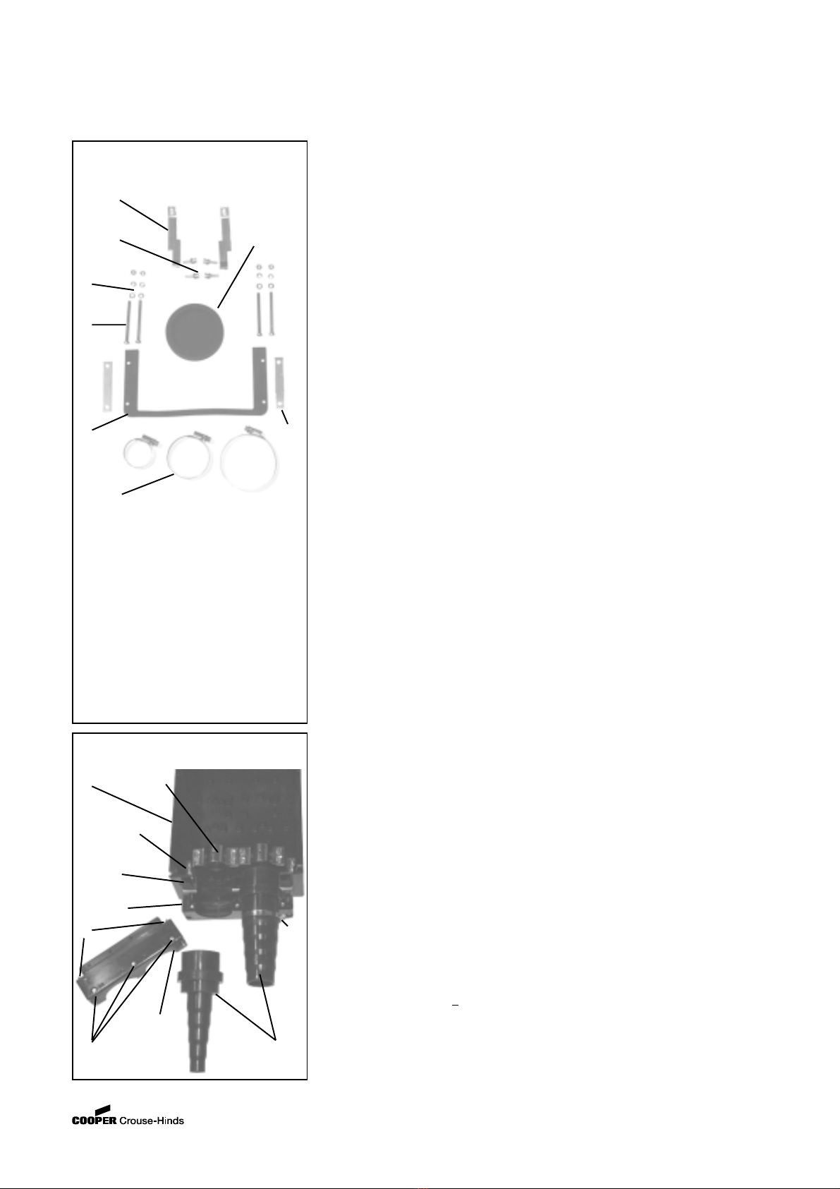
Nach der Montage des Kabels ist die
Kabeltülle mit der entsprechenden Spann-
schelle Pos. 8, abzudichten.
Zum Schluss wird das Oberteil Pos. 10,
aufgesetzt und mit den Befestigungs-
schrauben Pos. 4 und 12, festgeschraubt
sowie die Zugentlastung Pos. 14, wieder
montiert.
Die nicht benutzte Einführungsöffnung des
Doppelkabelendverschlusses ist mit einer
Verschlusstülle Pos. 5, (Bestellnummer
GHG 7401993 R0003) zu verschließen.
Achtung: Um die IP- Schutzart zu gewähr-
leisten, ist auf den korrekten Sitz der
Dichtung, Pos. 6, zu achten.
Beim Einsatz von KLE mit einer niedrigeren als
der für das Gerät zutreffenden IP-Schutzart,
(siehe Seite 3+4, technische Daten) wird die
IP-Schutzart des gesamten Gerätes reduziert.
Eigensichere Stromkreise sind über die
farblich (hellblau) gekennzeichneten KLE
einzuführen.
Um die Mindestschutzart herzustellen, sind
nicht benutzte Einführungsöffnungen mit
einem bescheinigten Verschlussstopfen zu
verschließen.
Es ist darauf zu achten, dass bei der Installati-
on der KLE die für den Leitungsdurchmesser
geeigneten Dichtungseinsätze verwendet
werden. Bei ausschneidbaren Dichtungs-
einsätzen ist sicherzustellen,dass der Einsatz
ordnungsgemäß dem Leitungsdurchmesser
angepasst wird.
Beim Einsatz von nur für fest verlegte
Leitungen geiegnete Kabel- und Leitungs-
einführungen ist sicherzustellen, dass keine
unzulässig hohe mechanische Beanspruchung
der Kabel- und Leitungseinführung oder deren
Dichtung erfolgt.
Zur Sicherstellung der erforderlichen Mindest-
schutzart sind die KLE fest anzuziehen.
Bei übermäßigem Anziehen kann die
Schutzart beeinträchtigt werden.
Achtung: Beim Anziehen der Hutmutter der
Metall-KLE (z.B. Typ E1WF/e) ist die
Verschraubung mit einem geeigneten
Werkzeug gegen Verdrehen zu sichern.
Alle nicht benutzten metrischen CCH / CEAG
KLE sind mit dem bescheinigten Verschluss
für metrische KLE zu verschließen.
6.4 Flansche, Metallplatten und
Außenerdung*
Müssen Flanschplatten demontiert werden
(z.B. zum Bohren von Einführungsöffnungen),
ist bei der Montage zur Aufrechterhaltung der
Mindestschutzart auf den korrekten Sitz der
Flanschplatte und den Sitz des Befestigungs-
bügels zu achten.
Von aussen herangeführte PE-Leitungen
sind auf die dafür vorgesehene PE-Klemme
am Flansch anzuschließen.
Ist eine seperate Außenerdung am Kunststoff-
gehäuse angebracht, darf dieser Anschluss mit
einer Leitung von max. 25mm² angeschlossen
werden.
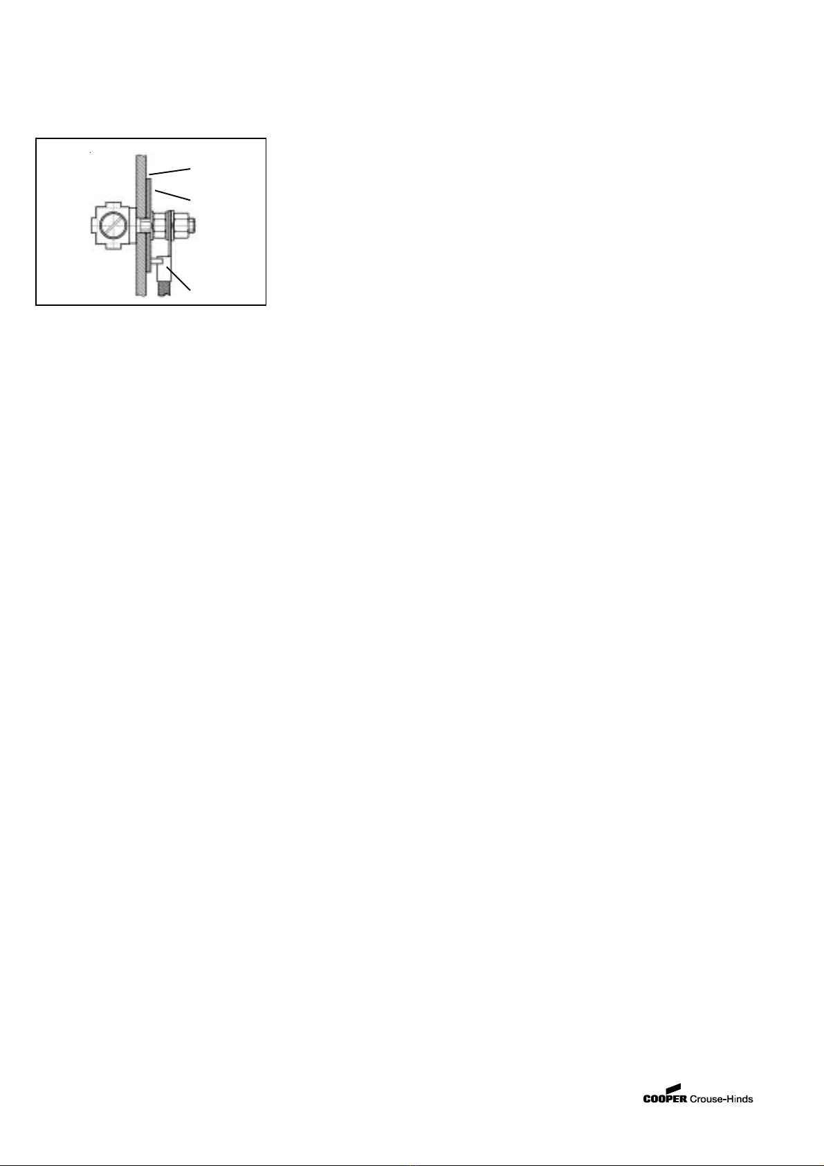
Dieser Außenerdungsanschluss ist innen im Ge-
häuse für einen Kabelschuhanschluss mit einem
Loch für M6 ausgelegt (siehe auch Bild 10).
Achtung: Metallflansche, Metallplatten und
Metallverschraubungen müssen in den
Potentialausgleich miteinbezogen werden.
* z.Zt. nicht bescheinigt für Kategorie II D
Bild 10 Außenerdung
Gehäuse-
innenwand
Erdungsplatte
Innenerdungs-
anschluss