manuals.online logo
Brands
  1. Home
  2. •
  3. Brands
  4. •
  5. Cooper Notification
  6. •
  7. Speakers
  8. •
  9. Cooper Notification E70 User manual

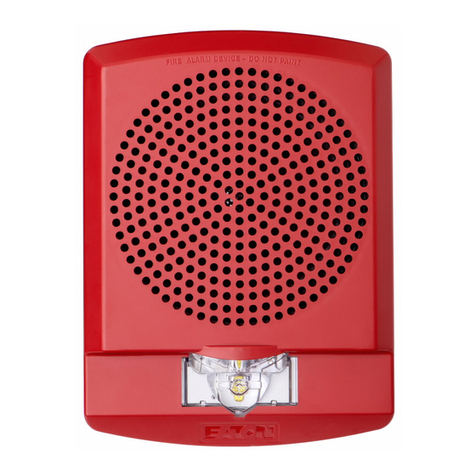
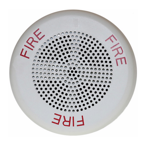
Cooper Notification E70 User manual

INSTALLATION INSTRUCTIONS
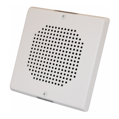
E70, E90 LOW PROFILE SPEAKER
(
WALL/CEILING MOUNT VERSION)
273 Branchport Ave.
Long Branch, N.J. 07740
(800) 631-
2148
www.coopernotification.com
PN P83566T Copyright 2021 Cooper Wheelock, Inc. dba Cooper Notification Page 1
Use this product according to this instruction manual. Please keep this instruction manual for future reference.
GENERAL:
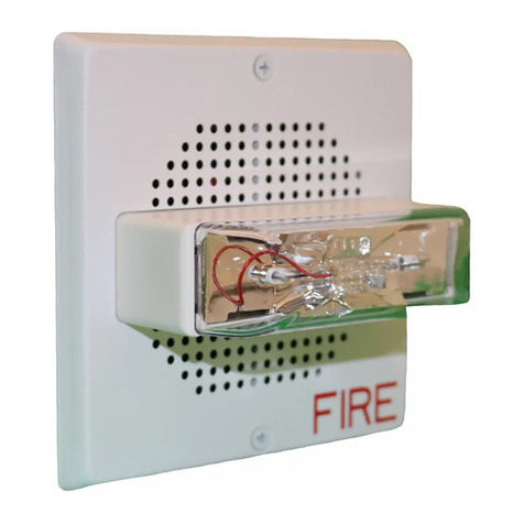
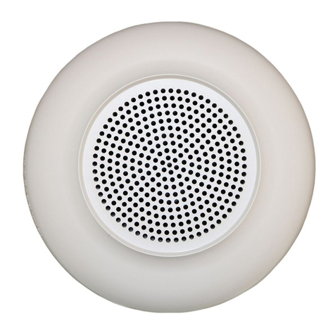
Series E70 and E90 Low Profile Speaker is UL Listed for indoor fire protection service under Standard UL1480 and ULC-S541-2016
(Speakers for Fire Alarm and Signaling Systems). The E70 and E90 speaker is designed for multiple power requirements with high dBA
output at each power tap and offer a choice of field selectable taps, 1/8W to 2W for either 25.0VRMS or 70.0VRMS audio systems. The
Low Profile design incorporates a high efficiency speaker for maximum output at minimum power across a frequency range of 400Hz to
4000Hz, and features a sealed back construction for extra protection and improved audibility. These models incorporate a speaker
mounting plate attached to the speaker for ease of installation, and are listed for indoor use with the backboxes specified in these
instructions (see mounting options).
CAUTION: Do not change factory applied finishes. “DO NOT PAINT”.
ATTENTION: Ne pas modifiez les finitions appliquées en usine. “NE PAS PEINTURER”
Table 1: Specifications
Model
E70 (Square Grille), E90 (Round Grille)
Agency
UL1480, ULC-S541-16
Speaker Input Voltage
25 or 70Vrms (field selectable, Table 3)
Speaker Frequency Range
400Hz to 4,000Hz
Settings
Speaker Wattage: 1/8 to 2 (field selectable, Table 3)
Supervision Voltage
33VDC Maximum
Environmental
Indoor Use Only. +32°F to 122°F (0°C to +50°C) 93% RH
Table 2A: Speaker Sound Pressure Level Ratings
Setting
Reverberant dBA at 10Ft per UL1480
Anechoic dBA at 10 Ft per ULC-S541
1/8
1/4
1/2
1
2
1/8
1/4
1/2
1
2
25 or 70.7Vrms
75
78
81
84
87
75
78
81
84
87
Table 2B: Directional Characteristics
-3dB
+/- 40 degrees horizontal; +/- 39 degrees vertical
-6dB
+/- 74 degrees horizontal; +/- 74 degrees vertical
NOTES:
1. Reverberant dBA is a minimum UL rating based on sound measurements in a reverberant test room.
2. This appliance does not generate a temporal pattern signal. If the distinctive three-pulse temporal pattern Fire Alarm Evacuation (or
total evacuation) in accordance with NFPA 72, is required, the control unit must be used with appliances that can generate the
temporal pattern signal. Refer to manufacturer's instruction manual for details.
WIRING DIAGRAMS:
Figure 1:
COM+
FROMPRECEDINGSPEAKER
ORFIREALARM
CONTROLPANEL(FACP)
TONEXTSPEAKER
ORENDORLINE RESISTO
(EOLR)
Figure 2:
*Refer to Sync Module instruction sheets DSM (P83177) or Wheelock’s Power Supplies for additional information.
1. This model has in-out wiring terminals that accept two #12 to #18 American Wire Gauge (AWG) wires at each screw terminal. Strip
leads 3/8 inches and connect to screw terminals.
2. Break all in-out wire runs on supervised circuits to assure integrity of circuit supervision as shown in Figure 2. The polarity shown in
the wiring diagrams is for operation of the appliances.
SETTINGS:
The Header(J1) on the PCB is used to select the speaker voltage/wattage and sound output level, see Figure 3.
Figure 3: Speaker Setting
A B C D E F G H
Factory setting is 70V, 1/2W, position “F”
Table 4: Speaker Voltage and Wattage Chart
Position
25V
70V
A
2W
------
B
1W
------
C
1/2W
------
D
1/4W
2W
E
1/8W
1W
F
------
1/2W
G
------
1/4W
H
------
1/8W
Each doubling of rated Watts increases sound output by 3dB
1. Use needle nose pliers to pull and properly insert the jumper plug to the desired setting of Voltage/Wattage.See Table 4.
2. Each letter corresponds to a position on the header located on the printed circuit board. See Figure 3..
3. A 1.5 µF blocking capacitor for DC supervision of audio lines by the FACP is factory wired in series with the speaker input.
Important: Always operate audio amplifiers and speakers within their specified ratings. Excessive input may distort sound quality and
may damage audio equipment. Do not exceed 100% of speaker input voltage per UL 1480. Improper input voltage can damage
speaker. If distortion is heard, check for clipping of the audio appliance with an oscilloscope and reduce the amplifier input level or gain
level to eliminate any clipping.
PN P83566T Page 2
MOUNTING OPTIONS:
The following figures (A,B) show the maximum number of field wires (conductors) that can enter the backbox used with each mounting
option. If these limits are exceeded, there may be insufficient space in the backbox to accommodate the field wires and stresses from the
wires could damage the product.
Check that the installed product will have sufficient clearance and wiring room prior to installing backboxes and conduit, especially if
sheathed multiconductor cable or 3/4" conduit fittings are used.
Figure A: Flush Mount with 4” Square Box & Ext. Ring
Figure B: Surface Mount with SBB
Note: Backbox is compatible with Wiremold and Conduit.
Mounting holes are for Single-Gang, Double-Gang,
4”SQ., 3-1/2” & 4” Octagon or Round Backboxes.
Maximum Number of Conductors
AWG #18 AWG#16 AWG #14 AWG #12
444 4
Maximum Number of Conductors
AWG #18 AWG#16 AWG #14 AWG #12
4444
All installations shall be in accordance with:
1) In the United States, the National Electrical Code, NFPA 70, and the National Fire Alarm and Signaling Code, NFPA 72.
2) In Canada, CSA C22.1, Canadian Electrical Code, Part I, Safety Standard for Electrical Installations, Section 32; and the Canadian
Standard for the Installation of Fire Alarm Systems - CAN/ULC-S524.
MOUNTING PROCEDURES:
1. Select a mounting option and install the backbox. Screws are provided. Conduit entrances to the backbox should be selected to
provide sufficient wiring clearance for the installed product. Do not pass additional wires (used for other than the signaling
appliance) through the backbox. Such additional wires could result in insufficient wiring space for the signaling appliance.
2. Verify appliance settings are correct for your application: Set Speaker Setting to match your Voltage/Wattage/dBA needs (Table 3,
Table 2A).
3. Connect field wiring to the appliance. When terminating field wires, do not use more lead length than required. Excess lead length
could result in insufficient wiring space for the appliance. Do not pass additional wires (used for other than the signaling appliance)
through the backbox. Such additional wires could result in insufficient wiring space for the signaling appliance.
4. Use care and proper techniques to position the field wires in the backbox so that they use minimum space and produce minimum
stress on the product. This is especially important for stiff, heavy gauge wires and wires with thick insulation or sheathing.
5. Use correct orientation for E70/E90 speaker mounting. The Speaker Mounting Plate must be oriented correctly when it is mounted
to the backbox. Turn the Speaker Mounting Plate so that the arrows adjacent to the word “TOP” point to the top side of the
Speaker Mounting Plate.
6. Mount the Speaker to the backbox. Next slide the grille over the Speaker and attach with (2) screws.
Important: Do not over tighten screws or terminals. Excessive torque may affect operation. When using power tools, ensure
the torque is set to the lowest setting available.
NOTE: Final acceptance is subject to Authorities Having Jurisdiction.
Check the installation instructions of the manufacturers of other equipment used in the system for any guidelines or restrictions on wiring
and/or locating Notification Appliance Circuits (NAC) and notification appliances. Some system communication circuits and/or audio
circuits, for example, may require special precautions to assure immunity from electrical noise (e.g. audio crosstalk).
This equipment has been tested and found to comply with the limits for a Class A digital device, pursuant to part 15 of the FCC Rules.
These limits are designed to provide reasonable protection against harmful interference when the equipment is operated in a commercial
environment. This equipment generates, uses, and can radiate radio frequency energy and, if not installed and used in accordance with
the instruction manual, may cause harmful interference to radio communications. Operation of this equipment in a residential area is likely
to cause harmful interference in which case the user will be required to correct the interference at his own expense.
This Class A digital apparatus meets all requirements of the Canadian Interference-Causing Equipment Regulations. Cet appareil
numérique de la classe A respecte toutes les exigences du Réglement sur le matériel brouilleur du Canada.
Any material extrapolated from this document or from Cooper Wheelock manuals or other documents describing the product for use in
promotional or advertising claims, or for any other use,including description of the product’s application, operation, installation and
testing is used at the sole risk of the user and Cooper Wheelock will not have any liability for such use.
IN NO CASE WILL SELLER’S LIABILITY EXCEED THE PURCHASE PRICE PAID FOR A PRODUCT.
3/21
This manual suits for next models

1

Other Cooper Notification Speakers manuals

Cooper Notification LSPK User manual

Cooper Notification

Cooper Notification LSPK User manual

Cooper Notification ET70-24MCW Series User manual

Cooper Notification

Cooper Notification ET70-24MCW Series User manual

Cooper Notification E70-24MCW-FW User manual

Cooper Notification

Cooper Notification E70-24MCW-FW User manual

Cooper Notification Wheelock E60H Series User manual

Cooper Notification

Cooper Notification Wheelock E60H Series User manual

Cooper Notification SPMNS User manual

Cooper Notification

Cooper Notification SPMNS User manual

Cooper Notification LSPKC User manual

Cooper Notification

Cooper Notification LSPKC User manual

Cooper Notification E60H-24MCC User manual

Cooper Notification

Cooper Notification E60H-24MCC User manual

Cooper Notification ET70-24MCC Series User manual

Cooper Notification

Cooper Notification ET70-24MCC Series User manual

Cooper Notification E50H-241575W User manual

Cooper Notification

Cooper Notification E50H-241575W User manual

Cooper Notification E70H Series User manual

Cooper Notification

Cooper Notification E70H Series User manual

Cooper Notification E70H Series User manual

Cooper Notification

Cooper Notification E70H Series User manual

Cooper Notification SA-S70 User manual

Cooper Notification

Cooper Notification SA-S70 User manual

Popular Speakers manuals by other brands

Turbosound NuQ PRO Series quick start guide

Turbosound

Turbosound NuQ PRO Series quick start guide

Onkyo NCP-302 Wi-Fi Set-up Guide

Onkyo

Onkyo NCP-302 Wi-Fi Set-up Guide

Stahl 8495 Series operating instructions

Stahl

Stahl 8495 Series operating instructions

EDIFIER S730 user manual

EDIFIER

EDIFIER S730 user manual

Behringer KX1200 user manual

Behringer

Behringer KX1200 user manual

Audibax DENVER 12 user manual

Audibax

Audibax DENVER 12 user manual

KEF Blade owner's manual

KEF

KEF Blade owner's manual

Definitive Technology C/L/R 2002 owner's manual

Definitive Technology

Definitive Technology C/L/R 2002 owner's manual

Fbt VERVE 8MA manual

Fbt

Fbt VERVE 8MA manual

REVELL I20 owner's manual

REVELL

REVELL I20 owner's manual

PRESONUS StudioLive 312AI Specifications

PRESONUS

PRESONUS StudioLive 312AI Specifications

Real-El M-590 Operation manual

Real-El

Real-El M-590 Operation manual

Pyle PKRK8 user manual

Pyle

Pyle PKRK8 user manual

LD LDEB82G3WMB user manual

LD

LD LDEB82G3WMB user manual

BP Technology CSM06T user manual

BP Technology

BP Technology CSM06T user manual

Pyle Tornado PLATV 520 user manual

Pyle

Pyle Tornado PLATV 520 user manual

Wohler VMQ-4 user guide

Wohler

Wohler VMQ-4 user guide

TriCom TCR-RCU-0X Operator's manual

TriCom

TriCom TCR-RCU-0X Operator's manual

manuals.online logo
manuals.online logoBrands
  • About & Mission
  • Contact us
  • Privacy Policy
  • Terms and Conditions

Copyright 2025 Manuals.Online. All Rights Reserved.