PN P84502E Page 2
SETTINGS:
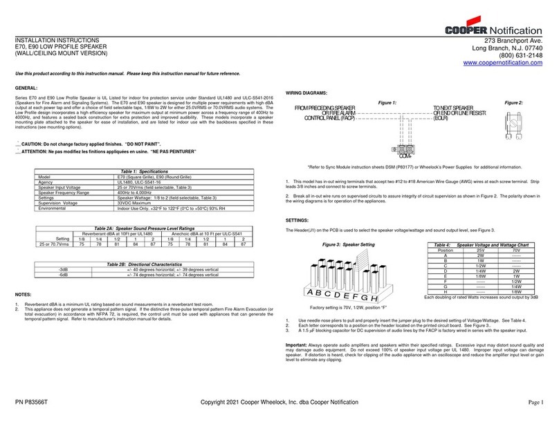
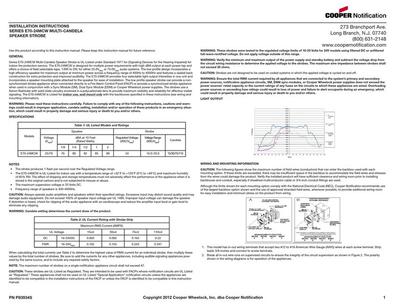
The switch on the PCB (SW1) is used to select the input voltage and sound output level, see Figure 3.
Figure 2:
S W 1
1234
SW1
1234
ST+
ST-
+24
GND
AD+
AD-
TB1
ON
ON
Figure 3:
POS 1
POS 2
POS 3
POS 4
SLIDE HERE FOR (0N)
SLIDE HERE FOR (OFF)
USE A SMALL SCREWDRIVER TO
CHANGE THE SWITCH POSITION
Table 3: Audio Input Voltage Mode Selection
Audio Input Voltage Mode
0.5 V RMS ON
: Sound Output Level Selection
Sound Output
Level
Relative Level
(dB)
Switch Settings (SW1)
POS 4 POS 3 POS 2
B
+3 (typical) OFF ON ON
6
0 (Reference) OFF OFF OFF
4 -6
(typical) ON ON OFF
3 -9
(typical) ON ON ON
1 -15
(typical) ON OFF ON
NOTES
1. These settings are not to be used in UL Listed applications and should be used in non-UL Listed applications only when the
audio input level is not at the rated value – 0.5 V RMS for the 0.5-V mode and 25 V RMS for the 25-V mode – to provide 3- or 6-dB
compensation for line losses and/or low drive levels. Using these settings while applying the rated audio input to the
appliance will cause excessive distortion and increased current consumption, and it is not a recommended operating
condition.
2. This is the setting used as a reference level for the other settings in Table 4.
3. These are typical values with respect to the reference level (Sound Output Level 6: 0 dB), and are included only to assist the user
in choosing a setting during installation. However, use the values in Table 2A, not these values, for the actual sound output
levels.
The following figures (A,B) show the maximum number of field wires (conductors) that can enter the backbox used with each mounting
option. If these limits are exceeded, there may be insufficient space in the backbox to accommodate the field wires and stresses from the
wires could damage the product.
Check that the installed product will have sufficient clearance and wiring room prior to installing backboxes and conduit, especially if
sheathed multiconductor cable or 3/4" conduit fittings are used.
MOUNTING OPTIONS:
Figure A: Flush Mount with 4” Square Box & Ext. Ring Figure B: Surface Mount with SBB
Maximum Number of Conductors
AWG #18 AWG#16 AWG #14 AWG #12
8 8 8 8
Maximum Number of Conductors
AWG #18 AWG#16 AWG #14 AWG #12
8 8 8 8
Wiring method shall be in accordance with:
1) In the United States, the National Electrical Code, NFPA 70, and the National Fire Alarm and Signaling Code, NFPA 72.
MOUNTING PROCEDURES:
1. Select a mounting option and install the backbox. Screws are provided. Conduit entrances to the backbox should be selected to
provide sufficient wiring clearance for the installed product. Do not pass additional wires (used for other than the signaling
appliance) through the backbox. Such additional wires could result in insufficient wiring space for the signaling appliance.
2. Verify appliance settings are correct for your application: Set SW1 to match your Audio Input Voltage (Table 3) and Output Sound
Level (Table 4).
3. Connect field wiring to the appliance. When terminating field wires, do not use more lead length than required. Excess lead length
could result in insufficient wiring space for the appliance. Do not pass additional wires (used for other than the signaling appliance)
through the backbox. Such additional wires could result in insufficient wiring space for the signaling appliance.
4. Use care and proper techniques to position the field wires in the backbox so that they use minimum space and produce minimum
stress on the product. This is especially important for stiff, heavy gauge wires and wires with thick insulation or sheathing.
5. Use correct orientation for SA speaker mounting. The Speaker Mounting Plate must be oriented correctly when it is mounted to
the backbox. Turn the Speaker Mounting Plate so that the arrow above the arrows and word “TOP” are on the top side of the
Speaker Mounting Plate.
6. Mount the Speaker to the backbox. Next slide the grille over the Speaker and attach with (2) screws.
Do not over tighten screws or terminals. Excessive torque may affect operation. When using power tools, ensure the torque is
set to the lowest setting available.
NOTE: Final acceptance is subject to Authorities Having Jurisdiction.
Check the installation instructions of the manufacturers of other equipment used in the system for any guidelines or restrictions on wiring
and/or locating Notification Appliance Circuits (NAC) and notification appliances. Some system communication circuits and/or audio
circuits, for example, may require special precautions to assure immunity from electrical noise (e.g. audio crosstalk).
This equipment has been tested and found to comply with the limits for a Class A digital device, pursuant to part 15 of the FCC Rules.
These limits are designed to provide reasonable protection against harmful interference when the equipment is operated in a commercial
environment. This equipment generates, uses, and can radiate radio frequency energy and, if not installed and used in accordance with
the instruction manual, may cause harmful interference to radio communications. Operation of this equipment in a residential area is likely
to cause harmful interference in which case the user will be required to correct the interference at his own expense.
Any material extrapolated from this document or from Cooper Wheelock manuals or other documents describing the product for use in
promotional or advertising claims, or for any other use,including description of the product’s application, operation, installation and
testing is used at the sole risk of the user and Cooper Wheelock will not have any liability for such use.
IN NO CASE WILL SELLER’S LIABILITY EXCEED THE PURCHASE PRICE PAID FOR A PRODUCT.
2/21


