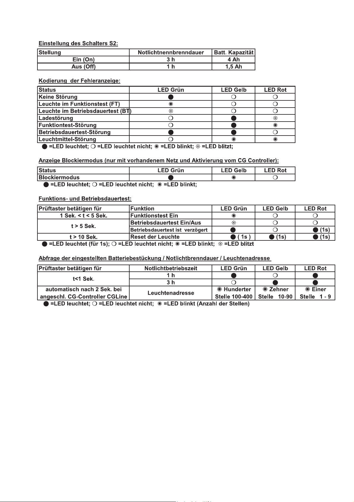
Cooper safety STYLE Variant 58011 CGLine Manual

1
Montage- und
Betriebsanleitung
Einzelbatterienotleuchte
Zielgruppe: Elektrofachkräfte
Fitting- and operating
instructions
Self-contained luminaire
Target group: Skilled electricians
STYLE Variant
58011 CGLine
58021 CGLine
400 71 350 096 (A)

2
Inhaltsverzeichnis / Index
Pos.Titel Seite
1 Aufbau 3
Maßbilder 4
2 Sicherheitshinweise 4
3 Normenkonformität/Verwendung 5
4 Technische Daten 5
5 Installation 5
5.1 Montage 5
5.2 Netzanschluss 5
5.3 Leuchte komplettieren 5
5.4 Schutzart IP54 5
5.5 Überwachung CGLine 6
LED- u. Batteriewahlschalterfunktionen 8
5.6 Zubehör 7
6 Wartung/Instandhaltung 7
7 Recycling 7
Pos.Titel Page
1 Construction 3
Dimensional drawings 4
2 Safety instructions 9
3 Conformity with standards 9
4 Technical data 9
5 Installation 9
5.1 Assembly 9
5.2 Mains connection 10
5.3 Complete luminaire 10
5.4 Degree of protection IP54 10
5.5 CGLine monitoring devices 10
Function of LED a. battery selector switch 11
5.6 Accessories 11
6 Maintenance / repair 12
7 Recycling 12

3
1. Leuchtenaufbau und Maßbilder Style Variant
58011 / 58021 CGLine
Construction and dimensional drawings Style Variant 58011/58021 CGLine
Style Variant 58011 CGLine
Style Variant 58021 CGLine
Leitungseinführungen
Cable entrys
Taster mit LEDs
Test button with
LEDs
Bild 1
Fig. 1
Gehäuse
Enclosure
Gehäuseoberteil
Enlosure top part
Akku
Lampenfassungen
Lamp socket
IP54 Haube optional mit
4 Befestigungsschrauben
IP 54 cover optional with
4 screws
IP54 Dichtung optional
IP54 seal optional
IP54 Dichtung für Gehäuse
optional
IP54 seal optional for enclosure
Rasthaken
Hooks
Netzanschlussklemmen
Mains terminals
Haube mit Piktogramm
Cover with legend
Leuchtmittel
Tube
Gehäuseoberteil
Enlosure top
part
Hohe Haube mit Piktogramm
High size cover with legend

4
1.1 Maßbilder
Dimensional drawings
Style Variant 58011 CGLine
Style Variant 58021CGLine
2. Sicherheitshinweise
Die Leuchte ist bestim-
mungsgemäß in unbeschä-
digtem und einwandfreiem
Zustand zu betreiben!
Als Ersatz dürfen nur
Originalteile von CEAG
verwendet werden!
Bei Arbeiten an der Not-
leuchte ist erst das Netz
(Ladephase und L’) abzu-
schalten und dann der
Batteriekreis zu unterbre-
chen. Bild 2 zeigt das
Hinweisschild auf der Not-
leuchte.
Vor der ersten Inbetrieb-
nahme muss die Leuchte
entsprechend den im Ab-
schnitt Installation genann-
ten Anweisungen geprüft
werden!
Die Notleuchtenkenn-
zeichnung vornehmen:
Stromkreis,Leuchtennummer
und ID-Nummer zuordnen
und eintragen.
Die manuelle Prüfbuchfüh-
rung ist nach den nationalen
Vorschriften durchzuführen.
Sie entfällt bei automatischer
Prüfbuchführung durch den
CG-Controller!
Alle Fremdkörper müssen
vor der ersten Inbetrieb-
nahme aus der Leuchte
entfernt werden!
Beachten Sie bei allen
Arbeiten an der Leuchte die
nationalen Sicherheits- und
Unfallverhütungsvorschrif-
ten und die nachfolgenden
Sicherheitshinweise in der
Betriebsanleitung, die mit
einem versehen sind!
Bild 2

5
3. Normenkonformität
Konform mit: EN 60 598-1,
EN 60 598-2-22, EN 1838,
DIN VDE 0108/10.89.
Niederspannungsrichtlinie
93/68/EWG
EMV-Richtlinie 89/336/EWG.
Hinweis: Trotz CE-Konformität
kann eine gegenseitige Beein-
flussung von Geräten und
Leuchten auftreten.
Gemäß DIN EN ISO 9001 ent-
wickelt, gefertigt und geprüft.
Eingangs- 230/240VAC
spannung: 50 Hz
Stromaufnahme: 70mA
Leistungsauf- 16 VA(8W)
nahme (AC):
Lampe : 8W/T16
Nennlichtstrom der 8W-
Lampe: 450 lm
Lichtstrom 40%(PhiE/PhiNenn)
am Ende d. Nennbetriebsdauer
Schutzklasse: II
Schutzart nach
EN 60527: IP 41
wahlweise: IP 54
Batterie: wiederaufladbar,
wartungsfrei, gasdicht
Notlicht 1h: NC-Akku 3,6V,1,5Ah
Notlicht 3h: NC-Akku 3,6V,4,0Ah
zulässige Umgebungstemp.:
Dauerlicht -5°C..+30°C
Bereitschaftslicht 0°C..+35°C
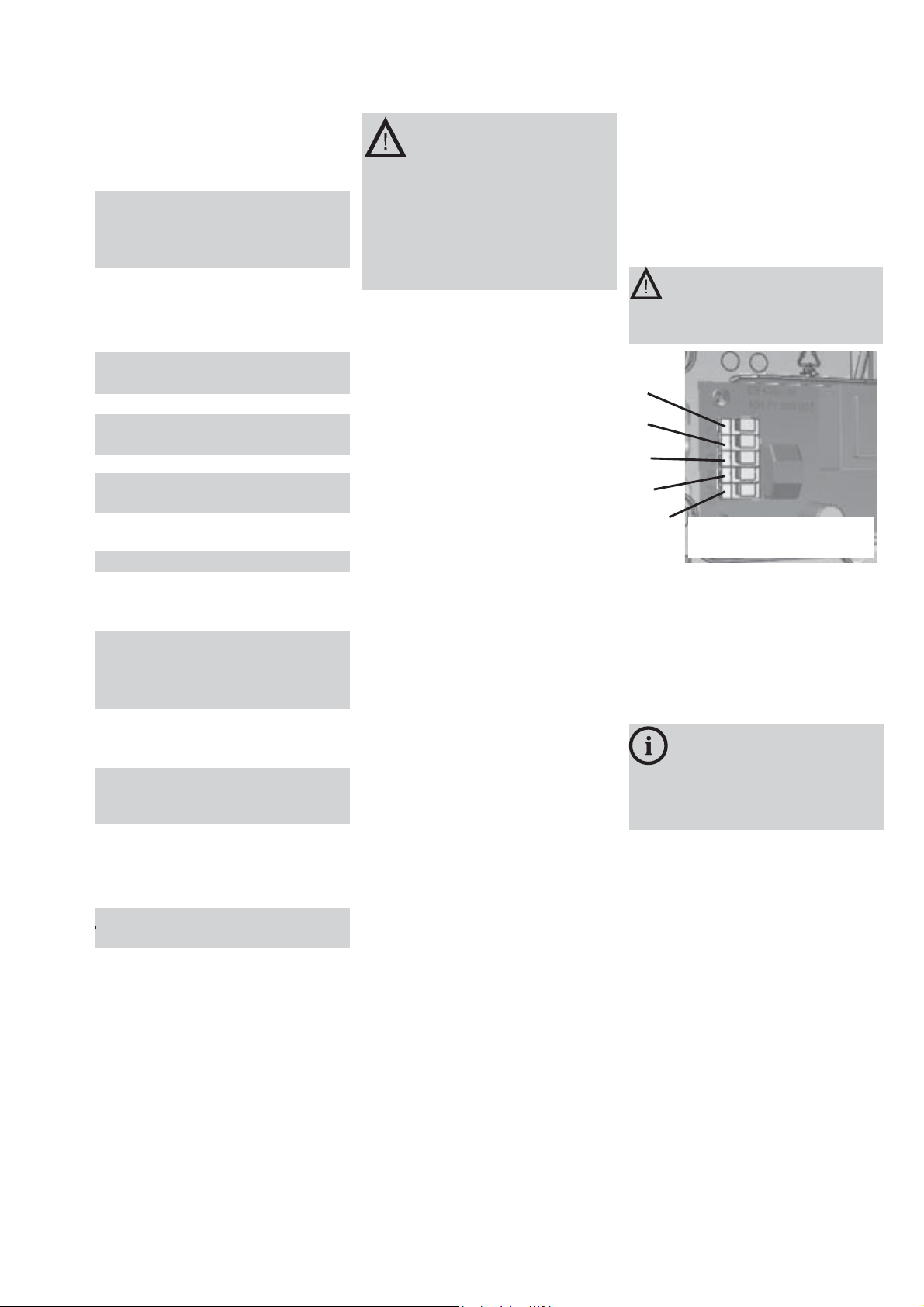
Netzanschlussklemmen:
3 x 2,5 mm²
Busklemmen: 2 x 1,5 mm2
Gewichte: 58011-1/D: 1,2kg
58011-3/D: 1,4kg
58021-1/D: 1,3kg
58021-3/D: 1,6kg
Abmessungen:
s. Maßbilder S.4
4.2 Kurzbeschreibung /
Verwendungsbereich
Die Rettungs- und Sicherheits-
leuchten STYLE Variant 58011 u.
58021 CGLine sind als Einzel-
batterieleuchten in Installationen
nach VDE 0108 geeignet.
Mit dem CEAG CG-Controller
CGLine 400 können die Einzel-
batterieleuchten über eine Bus-
leitung zentral überwacht wer-
den.
4. Technische Daten
5. Installation/
Inbetriebnahme
Halten Sie die für das Er-
richten und Betreiben
von elektrischen Betriebsmit-
teln geltenden Sicherheits-
vorschriften und das Geräte-
sicherheitsgesetz sowie die all-
gemein anerkannten Regeln
der Technik ein!
5.1 Montage
Style Variant 58011/
58021 CGLine
5.3 Leuchte komplettieren
Die Fastonstecker der Akkulei-
tungen auf die Kontaktstecker auf
der Leiterkarte aufstecken - rote
Leitung an + (Plus) , blaue Lei-
tung an - (Minus) (Bild 7).
Für die Nachvollziehbarkeit
der Batterie-Lebensdauer
bitte das Inbetriebnahme-Datum
in das auf der Batterie vorgese-
hene Feld eintragen.
5.2 Netzanschluss
Das Netzkabel ist an den Klem-
men N, L, L’ sowie an PE anzu-
schließen, wobei L als ungeschal-
tete Dauerversorgung der Elek-
tronik und L' über einen Licht-
schalter zur bedarfsabhängigen
Schaltung der Lampe dient (B.3).
PE muss als Funktionserde auch
bei Leuchten der Schutzklasse II
angeschlossen werden!
Lösen Sie die Haube durch Ein-
drücken der Seitenwände der
Haube (Bild 1) und heben Sie
diese vom Gehäuse ab.
Entfernen Sie das Leuchtmittel
aus den Lampenfassungen.
Lösen Sie 2 Schnapphaken auf
der Längsseite des Gehäuse-
oberteils mit einem Schlitz-
schraubendreher und heben Sie
das Gehäuseoberteil vom
Gehäuseunterteil ab. Nach
Installationsgegebenheit wahl-
weise vorgeprägte Leitungsein-
führungen seitlich oder an der
Rückseite ausbrechen. Lei-
tungseinführungsstopfen nach
Erfordernis einsetzen und je ein
Loch für den verwendeten Lei-
tungsdurchmesser einstanzen
oder einschneiden.
Bei Beschädigung der Dicht-
lippen ist die Leitungseinführung
zum Erhalt der Schutzart zu er-
setzen! Nicht benutzte, aber aus-
gebrochene Leitungseinführun-
gen sind mit dem Leitungsein-
führungsstopfen zu verschließen
(IP-Schutz).
Die Leitungen sind in den
Leuchtenkörper einzuführen und
der Leuchtenkörper ist mit ge-
eigneten, ausreichend dimensi-
onierten Schrauben durch die 4
an den Gehäuseecken liegenden
Löchern an Wand oder Decke
zu befestigen (Bild 4).
Bild 3
Fig.3
L
L
L’
N
PE )
Das Gehäuseoberteil aufsetzen
und alle 4 Schnappheken einras-
ten. Das Leuchtmittel in die Fas-
sungen einstecken und die
Leuchte durch Aufrasten der
Haube verschließen.
5.4 Schutzart IP54
(optional)
Durch Montage der IP 54-Dich-
tungen (rechteckig) zwischen Ge-
häuseunter- und Oberteil und der
Rundschnurdichtung zwischen
Gehäuseoberteil und IP54-Hau-
be und Montage der IP54-Hau-
be mit 4 Schrauben auf das Ge-
häuseoberteil ist der Raum über
dem Leuchtmittel und der Netz-
anschlussraum auf die Schutz-
art IP54 hochzurüsten (Bild1).
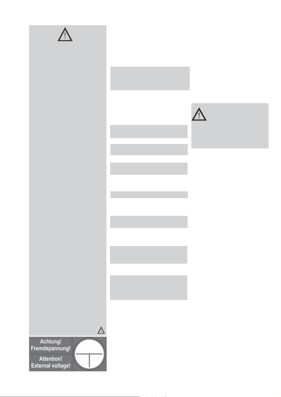
(nur Funktionserde!)
(only funktional earth!)
Achtung!
PE als Funktionserde an-
schließen.
Er hat keine Schutzfunktion!

6
Bild 4
Fig. 4
Befestigungslöcher 58011
Fixing holes
Bild 8
Fig. 8
Jede Leuchte kann wahlweise mit
bedarfsabhängiger Lichtschal-
tung (geschaltetes Dauerlicht), in
Bereitschaftslichtschaltung so-
wie in Dauerlichtschaltung be-
trieben werden (Bild 5).
Taster/LED-Folien-
Anschluss
Beim Wechsel von Taster/LED
oder Leiterkarte bitte Markie-
rung 1 auf der Leiterkarte und
auf der Leiterbahnfolie beach-
ten! (Bild 7)
5.5 Überwachungsein-
richtung CGLine
Die Leuchten Style Variant
58011/58021 CGLine sind für
den Anschluss an den CEAG
CG-Controller CGLine 400 vor-
bereitet (Bild 7).
Jeder Leuchte der Leuchten-
serie CGLine ist eine individuel-
le, unverwechselbare Identifi-
kationsnummer mit 6 Ziffern zu-
geordnet.
Diese ID-Nummer muss für spä-
tere Konfigurationsarbeiten in
den Installationsplan übertragen
werden.
Dazu dient der abziehbare ID-
Aufkleber in der Leuchte.
An eine 2-adrige Busleitung kön-
nen bis zu 100 Leuchten ange-
schlossen und mit dem CG-Con-
troller CGLine 400 verbunden
werden.
Max. 4 Busleitungen mit je 100
Leuchten kann der CG-Control-
ler überwachen.
Die max. Datenleitungs-
länge beträgt je Strang bei
0,5 mm2 - 450m
1,0 mm2 - 900m
1,5 mm2 - 1300m
Daten je Strang:
Busspannung: 22,5VDC
Max.Spg.-Abfall: 13VDC
Busstrom: 400mA
Als Datenleitung kann eine
ungeschirmte, 2-adrige Leitung
in freier Bus-Topologie zum Ein-
satz kommen.
Jede an der Daten-Bus-Leitung
angeschlossene Leuchte wird
vom CG-Controller automatisch
erkannt. Der CG-Controller kann
den angeschlossenen Leuchten
eine Kurzadresse zuweisen, die
über die drei LEDs an der Leuch-
te abgefragt werden kann.
Mit den drei LEDs (Bild 6, 8 und
Tab.1) an der Leuchte werden
nachstehende Statusanzeigen
angezeigt:
- keine Störung
- Leuchte im Funktionstest
- Leuchte im Betriebsdauertest
- Ladestörung
- Funktionstest - Störung
- Betriebsdauertest - Störung
- Leuchtmittel defekt
Bild 7
Fig.7
geschaltetes
Dauerlicht
Bild 5
Bereitschafts-
licht ohne,
Dauerlicht mit
Brücke
zwischen L
und L’
Markierung
Marker
CGLine-
Busanschluss
Bus connection
Taster/LED-
Anschluss
Button/LED
connection
+
_
Batterieanschluss
Battery connection
Batteriewahlschalter S1
Battery selector switch S1
1h 3h
1
Stecker
Taster/LED
Schild an der Leuchte
Information sign at the
luminaire
Bild 6
Fig.6
TEST
rot gelb grün
red yellow green

7
Zusätzlich können mit der Test-
Taste gestartet und angezeigt
werden:
- Funktionstest EIN
- Betriebsdauertest EIN / AUS
- Betriebsdauertest verzögert
- Einstellung der Notlichtbe-
triebszeit mit anschließender
Identifikation der Leuchten-
kurzadresse (bei angeschlos-
senem Datenbus sowie verge-
bener Kurzadresse durch den
CG-Controller).
Der verzögerte Betriebsdauer-
test wird angezeigt, wenn die
Leuchte nicht ununterbrochen
24 h geladen oder wenn inner-
halb der 24 h schon ein
Betriebsdauertest gestartet wur-
de.
Ein Reset der Leuchte wird aus-
gelöst, wenn die Testtaste
(Bild 6) länger als 10sek. ge-
drückt wird.
siehe Tabelle 1 Seite 8
Weitere Details siehe in der
Bedienungsanleitung des CG-
Controllers CGLine 400
Nr.:400 71 860 015
Autarker Betrieb
Nach der Erstinstallation / Netz-
anschluss wird wöchentlich ein
automatischer Funktionstest so-
wie alle 3 Monate ein Betriebs-
dauertest auch ohne CG-Cont-
roller CGLine gestartet.
Bild 9
5.6 Zubehör für
58011/58021 CGLine
Halten Sie die für die Inspek-
tion,Wartung,und Instandhaltung
von elektrischen Betriebsmitteln
geltenden Bestimmungen ein!
6. Inspektion/War-
tung/Instandhaltung
7. Entsorgung / Re-
cycling
Beachten Sie bei der Entsorgung
defekter Geräte die gültigen Vor-
schriften für Recycling und Ent-
sorgung.
Kunststoffteile sind mit entspre-
chenden Symbolen gekenn-
zeichnet.
Der in der Leuchte
eingebaute NiCd-
Akkus ist - entspre-
chend der EU-
Richtline 91/157/EWG - beim
Wechsel an den Vertreiber oder
an einen zugelassenen
Entsorger zurückzugeben und
darf nicht selbst entsorgt
werden!
Kettenbefestigung
Nr. 400 71 350 669
Wandausleger
Nr. 400 71 350 668
Das Gehäuseunterteil ist mit
den Zubehörteilen von innen
durch die Befestigungslöcher
mit den beiliegenden Gewinde-
schrauben zu verschrauben.
Bild 10

8
LED- und Batteriewahlschalterfunktionen
Tabelle 1
Technische Änderungen
vorbehalten!

9
2. Safety Instructions
The device shall only be used
for its intended purpose and
in undamaged and perfect
condition!
Only genuine CEAG spare
parts may be used for re-
placement and repair!
When working on the emer-
gency luminaire first cut off
mains (charging phase and
L’) and interrupt battery
operation. Fig. 13 shows the
indication label on the
emergency luminaire.
Prior to its initial operation, the
luminaire will have to be
checked in accordance with
the instructions as per
section Installation!
Carry out the marking of the
emergency luminaire: As-sign
the circuit, the luminaire no.
and ID-No. and enter them.
The manual log book shall be
performed in compliance with
the national regulations. It is
not applicable by automatical
log book with the CG-Con-
troller CGLine!
Any foreign matter shall be
removed from the luminaire
prior to its initial operation!
Observe the national safety
rules and regulations for pre-
vention of accidents as well
as the safety instructions
included in these operating
instruction marked with
3. Conformity with
Standards
Conforms to: EN 60 598-1,
EN 60 598-2-22, EN 1838, DIN
VDE 0108/10.89.
Low-voltage directive
93/68/EEC,
EMC directive 89/336/EEC.
Note: In spite of CE conformity,
there may be a mutual
influence on equipment and
luminaires.
Developed, manufactured and
tested in accordance with DIN
EN ISO 9001.
4. Technical data
Input voltage: 230/240 V AC
50 Hz
Rated current (AC): 70 mA
Power con-
sumption (AC): max.16VA (8W)
Lamp: 8 W/T16
Rated luminous flux
of the lamp: 450 lm
Rated luminous flux:
40% (phiE/phinominate)
at the end of operating cycle
Insulation class: I I
Protection category acc.
to EN 60529: IP 41
At option: IP 54
Accu: gas-tight,reloadable,
maintenance-free
Rated operating cycle:
1h: NC-accu 3,6V, 1,5Ah
3h: NC-accu 3,6V, 4,0Ah
Admissible ambient temperat.
maintained light: -5°C...+35°C
non maintained light:0°C...+30°C
Supply terminals: 3 x 2,5 mm²
Bus terminals: 2 x 1,5 mm2
Weight: 58011-1/D 1,2kg
58011-3/D 1,4kg
58021-1/D 1,3kg
58021-3/D 1,6kg
Dimensions: see dimensional
drawing on page 4
Fig. 13
4.2 Brief Description/Area
of Application
As a self-contained luminaire
the STYLE Variant 58011/
58021 CGLine emergency and
safety luminaire is suitable for
installations according to VDE
0108.
With the CEAG CG-Controller
CGLine 400 the self-contained
luminaires can be monitored
centrally via a bus cable.
5. Installation
For the mounting and
operation of electrical
apparatus, the respec-
tive national safety regulations
as well as the general rules of
engineering will have to be
observed.
5.1 Assembly
Style Variant 58011/58021
CGLine
Loosen the cover by pressing
the side panels of the cover
(Fig. 1) and lift it off the enclosure.
Remove the lamp from the lamp
fitting.
Loosen 2 snap-in hooks on the
long side of the top part of the
enclosure with a slotted screw-
driver and lift the top part of the
enclosure off the bottom part.
Depending on the installation
conditions, pierce the pre-drilled
cable entries on the side or the
back. Insert cable entry plugs
where necessary and punch or
cut one hole each for the cable
diameter used.
If the sealing lips are damaged,
the cable entry must be
replaced to preserve the degree
of protection! Unused, but
pierced cable entries must be
sealed with the cable entry plug
(IP degree of protection).
Insert the cables in the luminaire
and attach the luminaire to the
wall or ceiling with appropriate,
adequately sized screws
through the 4 holes at the corners
.f the enclosure (Fig. 4).

10
5.5 CGLine Monitoring
Device
The STYLE Variant 58011/
58021 CGLine luminaires are
prepared for connection to the
CEAG CG- Controller CGLine
400 (Fig. 7).
An individual, distinct identi-
fication number (6 characters)
is assigned to every luminaire
in the CGLine luminaire series.
This ID number must be
transferred to the installation
plan for subsequent
configuration work. The
removable ID sticker in the
luminaire can be used for this.
Up to 100 luminaires can be
connected to a 2-core bus
cable and linked to the CG-
Controller CGLine 400.
The CG-Controller can monitor
max. 4 bus cables with 100
luminaires each.
The max. data line length
per strand is
0.5 mm2- 450m
1.0 mm2- 900m
1.5 mm2- 1300m
Data per strand:
Bus voltage: 22.5VDC
Max. voltage drop: 13VDC
Bus current: 400mA
In addition, the following can
be started and displayed with
the test button:
- function test ON
- duration test ON / OFF
- duration test delayed
- setting the emergency light
operating time with
subsequent identification of
the luminaire short address
(when data bus is connected
and the CG-Controller has
issued short addresses).
The delayed duration test is
displayed if the luminaire is not
charged without interruption for
24 h or if an duration test is
started within the 24 h.
For further details see the
operating manual of the CG-
Controller CGLine 400
No.:400 71 860 016
Autarchic Operation
After the initial installation /
mains connection the luminaire
starts the function test weekly
and a duration test every three
months also without the
CG-Controller CGLine 400.
Button/LED-foil-connection
Changing button/LED or
printed circuit please see
marker 1 on the printed circuit
and on the printed conductor
(Fig. 7).
An unscreened, 2-core cable
with free bus topology can be
used as a data cable.
Each of the luminaires connected
to the data bus cable is auto-
matically recognised by the CG-
Controller. The CG-Controller
can assign a short address to
the connected luminaires, which
can be polled via the three LEDs
on the luminaire.
The three LEDs (Fig.6 and 8) on
the luminaire indicate the
following status:
- no fault
- luminaire in function test
- luminaire in duration test
- charging fault
- function test - fault
- duration test - fault
- luminescent material faulty
5.2 Mains Connection
Connect the mains cable to the
terminals N, L, L’ and PE,
where L is for unswitched per-
manent supply to the
electronics and L’ is used to
switch the lamp on and off via a
light switch (Fig. 3).
PE must be connected as
functional earth by luminaires
with insulation classII (two)!
Optionally, every luminaire can
be operated with light switch-
ing (switched maintained light),
in non maintained mode or in
maintained mode (Fig.14).
see Table 2 page 11
5.4 Degree of Protection
IP54 (optional)
The area above the lamp and
the mains connection area can
be upgraded to IP54 by fitting
the IP 54 seals (rectangular)
between the top and bottom of
the enclosure and the toroidal
sealing ring between the top of
the enclosure and IP54 cover
and fitting the IP54 cover with 4
screws to the top of the
enclosure.(Fig. 1)
5.3 Complete the Lumina-
ire
Plug the FASTON plug of the
battery wire to the contact plug
on the conductor board - red
wire to ++
++
+
(positive) , blue wire
to --
--
-(negative). (Fig. 7).
To fathom batteries life
please note start-up
date on the battery in the given
field!
Replace top of enclosure and
engage all 4 snap-in hooks. In-
sert the lamp in the fittings and
close the luminaire by sliding on
the cover.
switched
maintained
light
non maintained
light without and
maintained light
with jumper L
and L’
Fig. 14
For RESET of the luminaire
press the test button for about
10 sec.
Install PE as functional
earth. It has no function of
protection!

11
Function of LED and batterie selector switch
Tab. 2
5.6 Accessories Wall braket
No 400 71 350 668
Chain mounting
No 400 71 350 669
Use the enclosed threaded
screws to screw the bottom of
the housing to the accessories
from the inside through the
fixing holes.
Fig.15
Fig.16

12
CEAG Notlichtsysteme GmbH
Senator-Schwartz-Ring 26
D-59494 Soest / Germany
Telefon + 49 29 21/69-870
Telefax + 49 29 21/69-617
Internet http://www.ceag.de
E-Mail [email protected]
400 71 350 096 (A) / X /02.07/WES
6. Inspection/
Maintenance/Repair
Observe the valid regulations
for the inspection, maintenance
and repair of electrical
equipment!
When disposing of faulty
equipment, observe the valid
regulations for recycling and
disposal.
Plastic parts are marked with the
appropriate symbols.
The NiCd batteries
installed in the
luminaire comply with
EU directive 91/157/
EEC - when changing, return to
the distributor or to an
approved disposer; do not
dispose of it yourself!
We reserve the right to make
technical alterations without
notice.
7. Disposal/
Recycling
This manual suits for next models
1
Table of contents
Languages:
Popular Lantern manuals by other brands

Aurora
Aurora Aone A1GUZBCX5-AU quick start guide

Touch Of ECO
Touch Of ECO CAROLITE PRO Solar Candles instructions

Sollatek
Sollatek iGlow User instructions

RS Components
RS Components 616-037 Instruction leaflet

FLINQ
FLINQ GEMINI SET user manual

Home Decorators Collection
Home Decorators Collection 5273002 Use and care guide