Cooper safety CEAG 71811 LED CGLine 1-3/D Service manual


CEAG Notlichtsysteme GmbH 2
Montage- und Betriebsanleitung
Alu-Klick LED Einzelbatterienotleuchte
71811...71821 1-3/D LED CGLine
Inhaltsverzeichnis
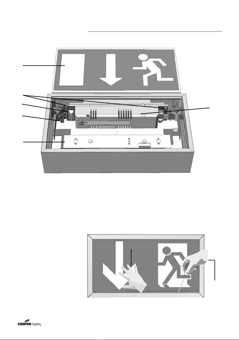
1 Aufbau der Leuchte / Construction of the luminaire............................. 3
1.1 RZ 71811 LED CGLine................................................................................................ 3
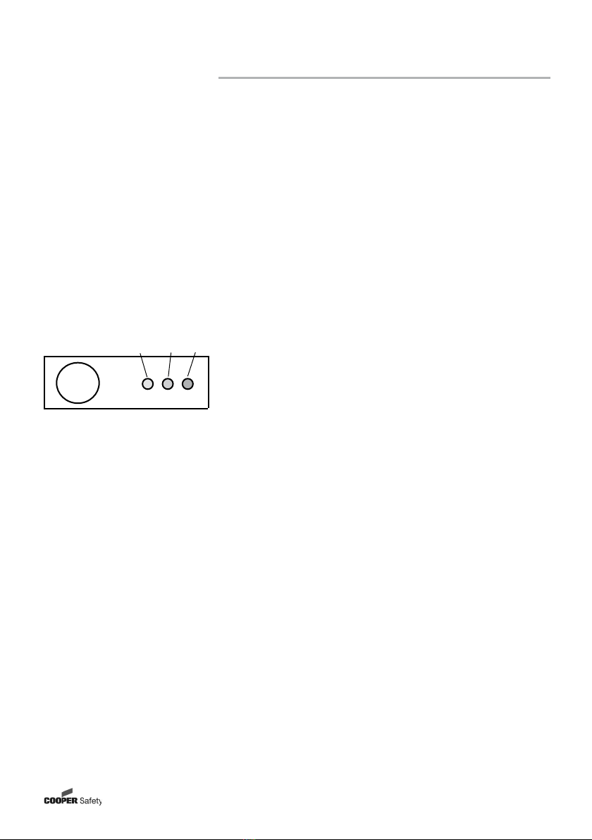
1.2 RZ 71821 LED CGLine................................................................................................ 4
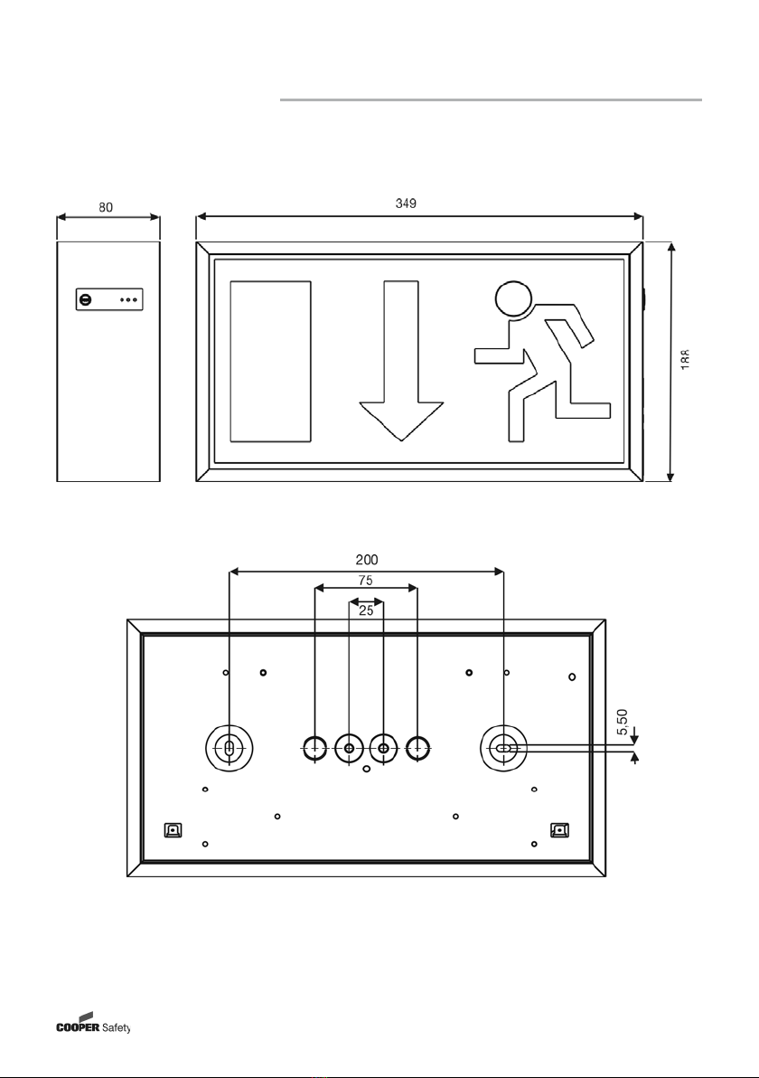
2 Maßbilder / Dimensional Drawings ....................................................... 5
2.1 71811 LED CGLine Decken-, o. Wandmontage / Ceiling or wall mounting .............. 5
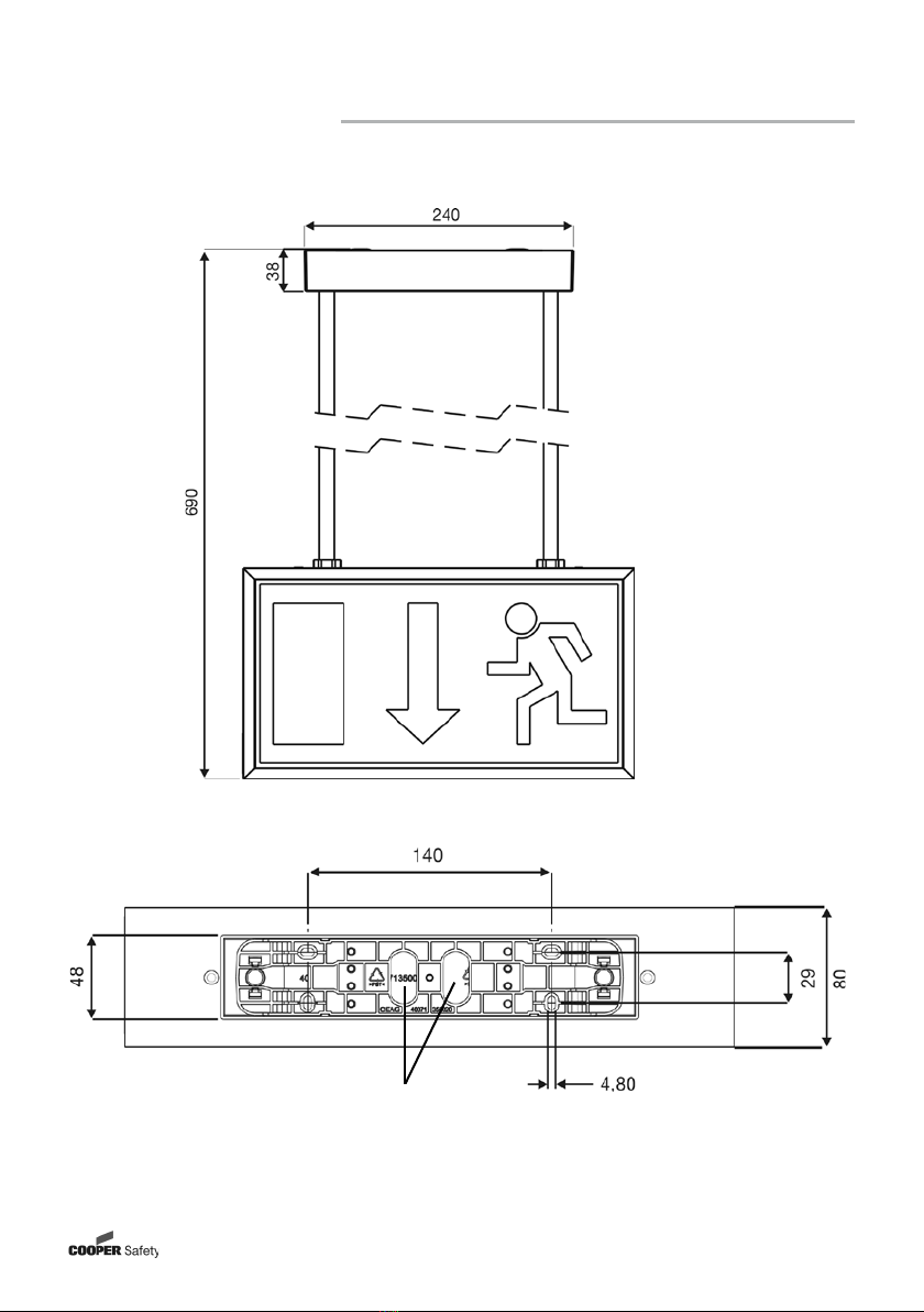
2.2 71821 LED CGLine Deckenmontage / Ceiling mounting........................................... 6
2.3 71821 LED CGLine Wandmontage / wall mounting................................................... 6
2.4 Einzelpendel 0,5m / Single Pendulum 0,5m für / for 71821 LED CGLine.................. 7
3 Sicherheitshinweise .............................................................................. 8
4 Normenkonformität ............................................................................... 8
5 Technische Daten.................................................................................. 8
5.1 Verwendungsbereich / Kurzbeschreibung ................................................................. 9
6 Installation / Inbetriebnahme................................................................. 9
6.1 Montage ..................................................................................................................... 9
6.2 Überwachtungseinrichtung CGLine......................................................................... 10
6.3 Dimmlevel................................................................................................................. 10
6.4 Einstellung der Betriebsart....................................................................................... 11
6.5 Kontroll LEDs ........................................................................................................... 11
7 Wartung / Instandhaltung.................................................................... 11
8 Entsorgung / Recycling....................................................................... 11
3 Safety notes ........................................................................................ 12
4 Conformity with standards.................................................................. 12
5 Technical data ..................................................................................... 12
5.1 Brief description / Scope of application................................................................... 13
6 Installation........................................................................................... 13
6.1 Mounting .................................................................................................................. 13
6.2 CGLine Monitoring Device ....................................................................................... 14
6.3 Dim-Level ................................................................................................................. 14
6.4 Operation mode ....................................................................................................... 15
6.5 Control LEDs ............................................................................................................ 15
7 Servicing ............................................................................................. 15
8 Recycling............................................................................................. 15

CEAG Notlichtsysteme GmbH 3
Montage- und Betriebsanleitung
Alu-Klick LED Einzelbatterienotleuchte
71811...71821 1-3/D LED CGLine
1.1 SL/RZ 71811 LED CGLine
Schließen:
Piktogramm-
scheibe nach
oben schieben
und unten ein-
rasten lassen.
To close:
Push cover up-
wards and snap
into enclosure
1 Aufbau der Leuchte / Construction of the luminaire
Abb. 1
1
2
3
4
5
1 Leuchtmittel / Leiste mit 3 Highpower LEDs / light strip with 3 Highpower LEDs
2 Netzanschlussklemme / mains terminal
3 PE - Anschluss / PE - connection
4 Versorgungsgerät V LED 4 CGLine mit integrierter Batterie /
supply module V LED 4 CGLine with integrated battery
5 Leitungseinführungen / cable entries
6 Befestigungslöcher / fixing holes
1
2
6

CEAG Notlichtsysteme GmbH 4
Montage- und Betriebsanleitung
Alu-Klick LED Einzelbatterienotleuchte
71811...71821 1-3/D LED CGLine
1.2 RZ 71821 LED CGLine
Montage der zweiseitigen Leuchte entnehmen Sie bitte dem individuellen Montageset.
For mounting the luminaire, please see the individual mounting accessory - set.
Öffnen:
Piktogrammscheibe nach
oben schieben (1) und unten
aus dem Rahmen heben, evtl.
mit Hilfe eines breiten Schrau-
bendrehers (2).
To open:
Push cover upwards and take out of en-
closure (1) - perhaps with the aid of a flat
screwdriver (2) 1
2
1
2
3
5
6
1 Leuchtmittel / Leiste mit 4 Highpower LEDs / light strip with 4 Highpower LEDs
2 PE - Anschluss / PE - connection
3 Netzklemme / mains terminal
4 Modulträger vor Deckenmontage lösen /
Remove module carrier before ceiling mounting
5 Beispiel: Piktogrammscheibe / example: pictogram cover
6 Versorgungsgerät V LED 4 CGLine mit integrierter Batterie /
supply module V LED 4 CGLine with integrated battery
Abb. 2
Abb. 3
4

CEAG Notlichtsysteme GmbH 5
Montage- und Betriebsanleitung
Alu-Klick LED Einzelbatterienotleuchte
71811...71821 1-3/D LED CGLine
2 Maßbilder / Dimensional Drawings
2.1 71811, Decken,- oder Wandmontage / Ceiling or wall mounting
Abb. 4
Abb. 5

CEAG Notlichtsysteme GmbH 6
Montage- und Betriebsanleitung
Alu-Klick LED Einzelbatterienotleuchte
71811...71821 1-3/D LED CGLine
2.2 71821, Deckenmontage / Ceiling mounting
2.3 71821, Wandmontage / Wall mounting
Abb. 6
Abb. 7
(*)
(*)
(*)
(*) = s. Zubehör in Pkt. 6.3 / see 6.3, accessories

CEAG Notlichtsysteme GmbH 7
Montage- und Betriebsanleitung
Alu-Klick LED Einzelbatterienotleuchte
71811...71821 1-3/D LED CGLine
2.4 Pendel Set 0,5m / Pendulum Set 0,5m für / for 71821
Abb. 8
Leitungseinfüh-
rungen / cable entries
Befestigungslöcher / fixing holes
Abb. 9
(*)

CEAG Notlichtsysteme GmbH 8
Montage- und Betriebsanleitung
Alu-Klick LED Einzelbatterienotleuchte
71811...71821 1-3/D LED CGLine
3. Sicherheitshinweise
pDie Leuchte ist bestimmungsgemäß in unbeschädigtem und einwandfreiem Zustand zu
betreiben!
pAls Ersatz dürfen nur Originalteile von CEAG verwendet werden!
pBei Arbeiten an der Notleuchte ist erst das Netz (Ladephase und L’) abzuschalten und dann der
Batteriekreis zu unterbrechen. Anbei das Hinweisschild auf der Notleuchte:
pVor der ersten Inbetriebnahme muss die Leuchte entsprechend den im Abschnitt Installation
genannten Anweisungen geprüft werden!
pDie Notleuchtenkennzeichnung vornehmen:
Stromkreis,Leuchtennummer und ID-Nummer zuordnen und eintragen.
pDie manuelle Prüfbuchführung ist nach den nationalen Vorschriften durchzuführen. Sie entfällt bei
automatischer Prüfbuchführung durch den CG-Controller oder das CGLine PC-Interface!
pAlle Fremdkörper müssen vor der ersten Inbetriebnahme aus der Leuchte entfernt werden!
pBeachten Sie bei allen Arbeiten an der Leuchte die nationalen Sicherheits- und Unfallverhü-
tungsvorschriften und die nachfolgenden Sicherheitshinweise in der Betriebsanleitung, die mit
einem versehen sind!
4. Normenkonformität
Die Leuchte ist konform mit: EN 60 598-1, EN 60 598-2-22 und DIN EN 1838.
Gemäß DIN EN ISO 9001 entwickelt, gefertigt und geprüft.
5. Technische Daten
Eingangsspannung: 230/240V AC / 50 Hz
Stromaufnahme (maximal):
71811 AC (RMS): 65mA
71821 AC (RMS): 115mA
Leistungsaufnahme (typisch) (AC):
71811 5,2 W ( 6,4 VA)
71821 6,9 W (11,0 VA)
Schutzklasse: I
Schutzart nach EN 60529: IP 41
Batterie: wiederaufladbar, wartungsfrei, gasdicht
NiMH-Akku 4,8V, 1,1Ah
zulässige Umgebungstemperatur Dauerlicht: -5°C...+30°C
Bereitschaftslicht: 0°C...+35°C
Netzanschlussklemmen: 3 x 2,5 mm²
Busklemmen: 2 x 1,5 mm2
Gewichte: 71811 1-3/D: 2,1kg
71821 1-3/D: 1,9kg

CEAG Notlichtsysteme GmbH 9
Montage- und Betriebsanleitung
Alu-Klick LED Einzelbatterienotleuchte
71811...71821 1-3/D LED CGLine
5.1 Kurzbeschreibung / Verwendungsbereich
Die Rettungszeichenleuchten Alu-Klick LED CGLine sind als Einzelbatterieleuchten in Installatio-
nen nach EN 50 172, DIN VDE 0100-718 und E DIN VDE 0108-100 geeignet.
Die EInzelbatterieleuchten CGLine können mit dem CEAG CG-Controller CGLine 400 oder dem
CEAG CGLine PC-Interface über eine Busleitung zentral überwacht werden.
6. Installation / Inbetriebnahme
Halten Sie die für das Errichten und Betreiben von elektrischen Betriebsmitteln geltenden
Sicherheitsvorschriften und das Gerätesicherheitsgesetz sowie die allgemein anerkannten
Regeln der Technik ein!
6.1 Montage
- Die Piktogrammscheibe mit Hilfe eines breiten Schraubendrehers entfernen (s. Abb 3).
- ggf. LED-Leiste entfernen
- Netzleitung einführen.
-
Gehäuse an den Befestigungslöchern mit 2 Schrauben und 2 Dübeln an die Decke/Wand montieren.
- Bei Pendel- und Kettenbefestigung werden diese lt. Zubehörset am Äußeren des Gehäuses befestigt.
Netzkabel an den Klemmen N, L, L‘ und Funktions-PE auf der Leiter
karte anschließen, wobei L als ungeschaltete Dauerversorgung der
Elektronik und L‘ über einen Lichtschalter zur bedarfsabhängigen
Schaltung über Lampe dient.
Jede Leuchte kann wahlweise mit bedarfsabhängiger Lichtschaltung
(geschaltetes Dauerlicht), in Bereitschaftslichtschaltung (ohne Brücke
L-L‘), sowie in Dauerlichtschaltung (mit Brücke L-L‘) betrieben wer-
den.
Bei Anschluss des LED Moduls auf Polarität achten!
Fastonstecker der Akkuleitungen auf die Kontaktstecker auf der Lei
terkarte aufstecken, rote Leitung an + (Plus), blaue Leitung an - (Mi-
nus).
Für die Nachvollziehbarkeit der Batterie-Lebensdauer bitte
das Inbetriebnahme-Datum in das auf der Batterie vorgese
hene Feld eintragen!
Scheibe wieder einsetzen (s. Abb. 1).
Taster/LED-Folien-Anschluss
Beim Wechsel von Taster/LED oder Leiterkarte bitte Markierung 1 auf der Leiterkarte und auf der
Leiterbahnfolie beachten!
L
L
L’
N
PE
geschaltetes
Dauerlicht
Bereitschafts-
licht
Betriebsartschalter S1
Aus Ein (1h/3h)
3h 1h
ON
OFF
1 2 3 4
Anschluss
LED Modul
Taster/LED-
Anschluss
CGLine-Bus
Anschluss

CEAG Notlichtsysteme GmbH 10
Montage- und Betriebsanleitung
Alu-Klick LED Einzelbatterienotleuchte
71811...71821 1-3/D LED CGLine
6.2 Überwachungseinrichtung CGLine
Die Alu-Klick Leuchten 71811/71821 LED CGLine sind für den Anschluss an den CEAG CG-Controller
CGLine 400 und dem CEAG CGLine PC-Interface vorbereitet. Jeder Leuchte der Leuchtenserie CGLine
ist eine individuelle, unverwechselbare Identifikationsnummer mit 6 Ziffern zugeordnet.
Diese ID-Nummer muss für spätere Konfigurationsarbeiten in den Installationsplan übertragen werden.
Dazu dient der abziehbare ID-Aufkleber in der Leuchte.
An den CG-Controller CGLine 400 und das CGLine PC-Interface können maximal 4 Busleitungen
(2-adrig) mit jeweils bis zu 100 Leuchten angeschlossen werden. Die max. Datenleitungslänge beträgt
je Strang bei
0,5 mm2 - 450m 1,0 mm2 - 900m 1,5 mm2 - 1300m
Busspannung: 22,5VDC
Max.Spg.-Abfall: 13VDC
Busstrom 400mA
Als Datenleitung kann eine ungeschirmte, 2-adrige Leitung in freier Bus-Topologie zum Einsatz kommen.
Jede an der Daten-Bus-Leitung angeschlossene Leuchte wird vom CG-Controller automatisch erkannt.
Der CG-Controller kann den angeschlossenen Leuchten eine Kurzadresse zuweisen, die über die drei
LEDs an der Leuchte abgefragt werden kann.
Mit der Test-Taste können gestartet und angezeigt werden:
- Funktionstest EIN
- Betriebsdauertest EIN / AUS
- Betriebsdauertest verzögert
- Eingestellte Notlichtbetriebszeit mit anschließender Identifikation der Leuchtenkurzadresse (bei
angeschlossenem Datenbus sowie vergebener Kurzadresse durch den CG-Controller).
Der verzögerte Betriebsdauertest wird angezeigt, wenn die Leuchte nicht ununterbrochen 24 h geladen
oder wenn innerhalb der 24 h schon ein Betriebsdauertest gestartet wurde.
Weitere Details in nachfolgender Tabelle sowie in der Bedienungsanleitung des CG-Controllers CGLine
400 oder das CGLine PC-Interface,
Autarker Betrieb
Ohne CG-Controller CGLine 400 oder CGLine PC-Interface wird nach der Erstinstallation / Netzan-
schluss wöchentlich ein automatischer Funktionstest sowie alle 3 Monate ein Betriebsdauertest
gestartet.
Nach Netzwiederkehr läuft das Notlicht noch ca. eine Minute nach (nachlaufendes Notlicht)!
6.3 Dimmlevel
Einstellen der LED-Helligkeit im Netzbetrieb durch Betätigung des Prüftasters:
Programmiersequenz:
- Betätigung des Prüftasters für t < 1sec.
- Nach erstmaligem Aufleuchten der LED kann nun die Helligkeit durch erneutes Bestätigen des
Prüftasters in 3 Stufen verändert werden. Bei jedem Tastendruck wird die Helligkeit um eine Stufe
erhöht. Ist die höchste Stufe erreicht, wird wieder bei der Niedrigsten begonnen.
TEST
grün gelb rot

CEAG Notlichtsysteme GmbH 11
Montage- und Betriebsanleitung
Alu-Klick LED Einzelbatterienotleuchte
71811...71821 1-3/D LED CGLine
Technische Änderungen vorbehalten!
7. Inspektion/Wartung/Instandhaltung
Halten Sie die für die Inspektion,Wartung und Instandhaltung von elektrischen Betriebsmitteln
geltenden Bestimmungen ein!
8. Entsorgung / Recycling
Beachten Sie bei der Entsorgung defekter Geräte die gültigen Vorschriften für Recycling und Entsor-
gung. Kunststoffteile sind mit entsprechenden Symbolen gekennzeichnet.
Der in der Leuchte eingebaute NiMh-Akku ist - entsprechend der EU-Richtline 2006/66/
EG - beim Wechsel an den Vertreiber oder an einen zugelassenen Entsorger zurückzu-
geben und darf nicht selbst entsorgt werden!
Im Fall von Rücksendungen benötigen Sie von uns eine RMA - Nummer.
Entnehmen Sie bitte weitere Infos hierzu unserer Internetseite www.ceag.de!
6.4 Einstellung der Betriebsart
1 = ON; 0 = OFF
6.5 Kontroll-LEDs
Einstellung der Schalter S1-X:
Notlichtdauer Anzahl LEDs Leuchtentyp S1-1 S1-2 S1-3 S1-4
1h 4 71811 LED CGLine 0 0 0 1
3h** 4 71811 LED CGLine 1 0 0 1
1h 8 71821 LED CGLine 0 0 0 0
3h** 8 71821 LED CGLine 1 0 0 0
**) werkseitige Einstellung
Leiterkarte
Blockiermodus
Funktions- und Betriebsdauertest:
=LED leuchtet (für 1s); =LED leuchtet nicht; =LED blinkt; =LED blitz
t
Abfrage der eingestellten Batteriebestückung / Notlichtbetriebszeit / Leuchtenadresse
=LED leuchtet; =LED leuchtet nicht; =LED blinkt (Anzahl der Stellen
)
dann blinkt LED rot 5 mal
1 - 9(max. 9x)
dann blinkt LED rot 5 mal
Einstellung des Schalters S1-1:
Stellung: 1 = ON; 0 = OFF Notlichtnennbrenndauer
1 3 h
0 1 h
Kodierung der Fehleranzeige:
Status LED Grün LED Gelb LED Rot
Keine Störung
Notlicht
Nachlaufendes Notlicht (ca. 1 Min.)
im Wechsel ca. 1 Sek.
Leuchte im Funktionstest (FT)
Leuchte im Betriebsdauertest (BT)
Ladestörung
Funktiontest-Störung
Betriebsdauertest-Störung
Leuchtmittel-Störung
=LED leuchtet; =LED leuchtet nicht; =LED blinkt; =LED blitzt;
Anzeige Blockiermodus (nur mit vorhandenem Netz und Aktivierung vom CG Controller):
Status LED Grün LED Gelb LED Rot
Blockiermodus
=LED leuchtet; =LED leuchtet nicht; =LED blinkt;
Prüftaster betätigen für Funktion LED Grün LED Gelb LED Rot
1 Sek. < t < 5 Sek.
t > 5 Sek.
Funktionstest Ein
Betriebsdauertest Ein/Aus
Betriebsdauertest ist verzögert (1s)
t > 10 Sek. Reset der Leuchte ( 1s ) (1s) (1s)
Prüftaster betätigen für
t<1 Sek.
Notlichtbetriebszeit LED Grün LED Gelb LED Rot
1 h
automatisch nach 2 Sek. bei a Leuchte
ngeschl.
3 h
nadresse
100-400(max. 4x) 10-90(max. 9x)
Controller CGLine 400
Beispiel: Adresse 25
Erst blinkt LED gelb 2 mal
3h 1h
ON
OFF
1 2 3 4

CEAG Notlichtsysteme GmbH 12
Operating Instructions
Alu-Klick LED self contained luminaire
71811...71821 1-3/D LED CGLine
3. Safety Notes
pThe luminaire shall only be used for its intended purpose and in an indamaged and perfect
condition!
pOnly genuine CEAG spare parts may be used for replacement and repair!
pWhen working on the emergency luminaire first cut off mains (charging phase and L’) and inter-
rupt battery operation. Enclosed indication label on the emergency luminaire:
pPrior to its initial operation, the luminaire will have to be checked in accordance with the instruc-
tions as per section ‘Installation’!
pCarry out the marking of the emergency luminaire:
Assign the circuit, the luminaire no. and ID no. and enter them.
pThe manual log book shall be performed in compliance with the national regulations. It is not
applicable by automatical log book with the CG-Controller CGLine or the CGLine PC-Interface!
pAny foreign matter shall be removed from the luminaire prior to its initial operation!
pObserve the national safety rules and regulations for prevention of accidents as well as the safety
instructions included in these operating instructions marked with !
4. Conformity to standards
Conforms to: EN 60 598-1, EN 60 598-2-22 and DIN EN 1838.
Developed, manufactured and tested in accordance with DIN EN ISO 9001.
5. Technical Data
Input voltage: 230/240V AC / 50 Hz
Current consumption (maximum):
71811 AC (RMS): 65mA
71821 AC (RMS): 115mA
Power consumption (typical) (AC):
71811 5.2 W ( 6.4 VA)
71821 6.9 W (11.0 VA)
Insulation class: I
Degree of protection acc. to EN 60529: IP 41
Battery: gas-tight, reloadable, maintenance-free
NiMH-Accu 4,8V, 1,1Ah
Admissible amb. temperature Maintained Light: -5°C...+30°C
Non Maintained Light: 0°C...+35°C
Supply terminals: 3 x 2,5 mm²
Bus terminals: 2 x 1,5 mm2
Weight: 71811 1-3/D: 2,1kg
71821 1-3/D: 1,9kg

CEAG Notlichtsysteme GmbH 13
Operating Instructions
Alu-Klick LED self contained luminaire
71811...71821 1-3/D LED CGLine
5.1 Brief description / Scope of application
As a self contained aluminium luminaire the 71811_71821 LED CGLine emergency and safety lumi-
naire is suitable for installations acc. to EN 50 172, DIN VDE 0100-718 and E DIN VDE 0108-100.
With the CEAG CG-Controller CGLine 400 or the CGLine PC-Interface the self-contained luminaires
can be monitored centrally via a bus cable.
6. Installation / Operation
For the mounting and operation of electrical apparatus, the respective national safety
regulations as well as the general rules of engineering will have to be observed!
6.1 Mounting
- Remove cover with the help of a flat screw driver (s. fig. 3) and, if needed, remove LED strip
- Introduce mains cable.
- Mount enclosure with 2 screws and 2 dowels through the fixing holes at the ceiling or wall.
- For pendulum set mounting and chain suspension see manual of accessory set
.
Mains cable should be connected to the terminals N, L, L‘ and PE on
the printed circuit board, where L is an unswitched permanent con-
nection for the electronics and L‘ is used for switching the lamp on
and off with a light switch as and when required.
Optionally, every luminaire can be operated with light switching (swit-
ched maintained light), in non maintained mode or in maintained
mode.
When connecting the LED module please observe the polarity!
Plug the faston plugs of the battery cables to the contact plugs on
the conductor board - red wire to + (plus), blue wire to - (minus).
To fathom batteries life please note the start up date on the
battery in the given data field!
Insert cover (s. fig. 1).
Button /LED-foil-connection
Changing button/LED or printed circuit board please see marker 1 on the printed circuit board and
on the printed conductor!
L
L
L’
N
PE
switched
maintained light
non maintained
light
Operation mode switch S1
OFF ON (1h/3h)
3h 1h
ON
OFF
1 2 3 4
Connection
LED module
Button/LED-
connetion
CGLine-Bus
connection

CEAG Notlichtsysteme GmbH 14
Operating Instructions
Alu-Klick LED self contained luminaire
71811...71821 1-3/D LED CGLine
6.2 CGLine Monitoring Device
The Alu-Klick luminaires 71811/71821 LED CGLine are prepared for connection to the CEAG CG-
Controller CGLine 400 or the CGLine PC-Interface. An individual, distinct identification number (6
characters) is assigned to every luminaire in the CGLine luminaire series.
This ID number must be transferred to the installation plan for subsequent configuration work. The
removable ID sticker in the luminaire can be used for this.
To the CG-Controller CGLine 400 or the CGLine PC-Interface max. 4 bus cables (2-core) with up to
100 luminaires each can be connected. The max. data line length per strand is
0,5 mm2 - 450m 1,0 mm2 - 900m 1,5 mm2 - 1300m
Bus voltage: 22,5VDC
Max.voltage drop: 13VDC
Bus current 400mA
An unscreened, 2-core cable with free bus topology can be used as a data cable.
Each of the luminaires connected to the data bus cable is automatically recognised by the CG-Controller.
The CG-Controller can assign a short address to the connected luminaires, which can be polled via
the three LEDs on the luminaire.
The following can be started and displayed with the test-button:
- function test ON
- duration test ON/OFF
- duration test delayed
- settings of the emergencylight operating time with subsequent identification of the luminaire short
address (when data bus is connected and the CG-Controller has issued short addresses).
The delayed duration test is displayed if the luminaire is not charged without interruption for 24h or if
an duration test is started within the 24h.
For further details see the operating manual of the CG-Controllers CGLine 400 or the CGLine PC-
Interface.
Autarkic operation
Without the CG-Controller CGLine the luminaire starts after the initial installation/mains connection
the function test weekly and a duration test every three months. After mains returns the emergency
operation will stay for approx. 1 minute (delay on mains return)!
6.3 Dim-Level
Setting the brightness in mains mode by using the test button
- Push the test-button for t < 1 sec.
- After the first flash of the LED the lightness can be changed by pushing the button again in 3
steps. Every push of the button raises the lightness for 1 step. If the hightest step is reached it
begins again with the lowest.
TEST
green yellow red

CEAG Notlichtsysteme GmbH 15
Operating Instructions
Alu-Klick LED self contained luminaire
71811...71821 1-3/D LED CGLine
6.4 Operation mode
1 = ON; 0 = OFF
6.5 Control LEDs
We reserve the right to make technical
alterations without notice!
7. Inspection/Maintenance/Repair
Observe the valid regulations for the inspection, maintenance and repair of electrical equipement!
8. Disposal / Recycling
When disposing of faulty equipment, observe the valid regulations for recycling and disposal. Plastic
parts are marked with the appropriate symbols.
According to EU-directive 2006/66/EG the NiMh-batteries, which are installed in the lumin-
aires, has not to be disposed by yourself! Return to the distributor or to an appoved dispo-
ser!
In case of returns you need a RMA - number from us. For further information see
www.ceag.de!
Position of the switches S1-X:
duration of e.l. no. of LEDs Type of luminaire S1-1 S1-2 S1-3 S1-4
1h 4 71811 LED CGLine 0 0 0 1
3h** 4 71811 LED CGLine 1 0 0 1
1h 8 71821 LED CGLine 0 0 0 0
3h** 8 71821 LED CGLine 1 0 0 0
**) preset
printed cir-
cuit board
Position of battery selector switch S1-1
Position: 1 = ON; 0 = OFF
Rated operating cycle
1 3 h
0 1 h
Coding of the fault display:
Status LED green LED yellow LED red
No failure
Emergency mode
Delay-time on mains return (ap.1 min.) alternately 1 sec.
Luminaire in function test
Luminaire in duration test
Charging fault
Fault in function test
Fault in duration test
Fault with luminescent material
=LED lights up; =LED does not light up; =LED blinks; =LED flashes;
Indication block mode (with main voltage and activation of CG-Controller only)
Status LED green LED yellow LED red
Block mode
=LED lights up; =LED does not light up; =LED flashes;
Test button funktions
Test button pressed for: Function LED green LED yellow LED red
1 sec. < t < 5 sec. Function test On
t > 5 sec. Duration test On / Off
Duration test delayed (1s)
t > 10 sec. Reset of the luminaire ( 1s ) (1s) (1s)
=LED lights up (für 1s); =LED does not light up; =LED blinks; =LED flashes
Monitoring of the adjusted battery mounting / emergency operating time / address of the luminaires
Test button pressed for: Emergency operating time LED green LED yellow LED red
t<1 sec. 1 h
3 h
automatically after 2 sec.with connected
CG-Controller CGLine 400 Address of the luminares
Hundred
digit 100-400
Ten digit
10-90
One digit
1 - 9
=LED lights up; =LED does not light up; =LED blinks (Number of digits)
Example: Address 25
first blinks LED yellow 2 times
than blinks LED red 5 times
3h 1h
ON
OFF
1 2 3 4

400 71 351 473 (B)/XXX/07.10/WK
This manual suits for next models
1
Table of contents
Languages:
Other Cooper safety Security Sensor manuals
Popular Security Sensor manuals by other brands

MSA
MSA altair 4 Quick start card

Tecnosystemi
Tecnosystemi Toolsplit TSCE-900 user manual

HumanTechnik
HumanTechnik Signolux A-2672-0 user manual

Powerfix Profi
Powerfix Profi Z31712A/C Operation and safety notes

Detection Systems
Detection Systems DS433i installation instructions

Hochiki America Corporation
Hochiki America Corporation ALO-V Installation and maintenance instructions