9
Montage- und Betriebsanleitung
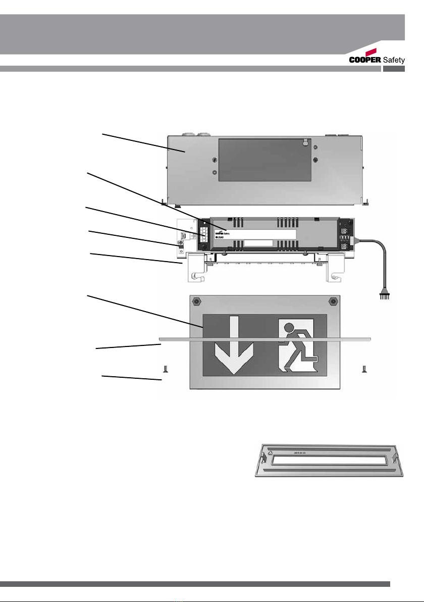
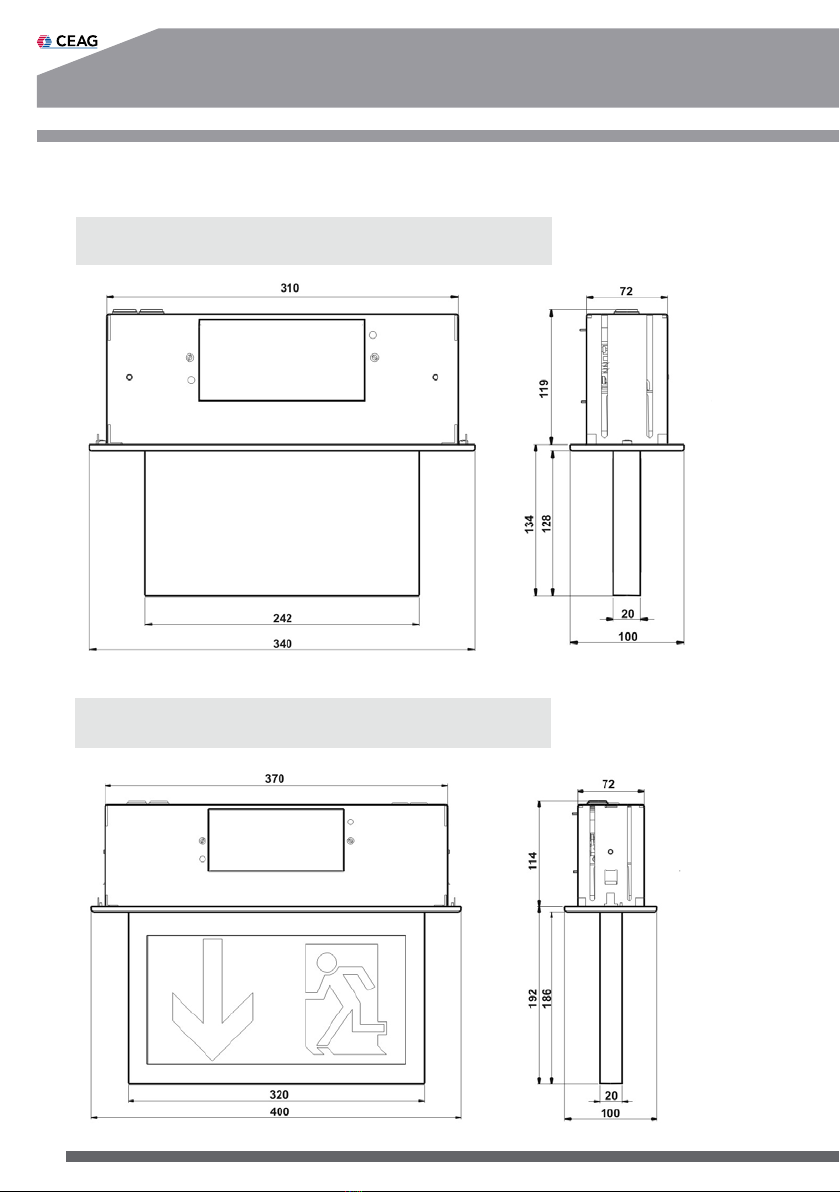
Brillant LED Deckeneinbau-Einzelbatterieleuchte
1883...1884 LED CGLine
6.4 Kontroll-LEDs
Technische Änderungen vorbehalten!
7. Inspektion/Wartung/Instandhaltung
Halten Sie die für die Inspektion,Wartung und Instandhaltung von elektrischen Betriebsmitteln
geltenden Bestimmungen ein!
8. Entsorgung / Recycling
Beachten Sie bei der Entsorgung defekter Geräte die gültigen Vorschriften für Recycling und Entsor-
gung. Kunststoffteile sind mit entsprechenden Symbolen gekennzeichnet.
Der in der Leuchte eingebaute NiMh-Akkus ist - entsprechend der EU-Richtline 2006/66/
EG - beim Wechsel an den Vertreiber oder an einen zugelassenen Entsorger zurückzu-
geben und darf nicht selbst entsorgt werden!
Im Fall von Rücksendungen benötigen Sie von uns eine RMA - Nummer.
Entnehmen Sie bitte weitere Infos hierzu unserer Internetseite www.ceag.de!
Kodierung der Fehleranzeige:
Status LED Grün LED Gelb LED Rot
Keine Störung
Notlicht
Nachlaufendes Notlicht
Leuchte im Funktionstest (FT)
Leuchte im Betriebsdauertest (BT)
Ladestörung
Funktiontest-Störung
Betriebsdauertest-Störung
Leuchtmittel-Störung
Anzeige Blockiermodus (nur mit vorhandenem Netz und Aktivierung vom CG Controller):
Status LED Grün LED Gelb LED Rot
Blockiermodus
=LED leuchtet; =LED leuchtet nicht; =LED blinkt;
Funktions- und Betriebsdauertest:
Prüftaster betätigen für Funktion LED Grün LED Gelb LED Rot
1 Sek. < t < 5 Sek. Funktionstest Ein
Betriebsdauertest Ein/Aus
Betriebsdauertest ist verzögert (1s)
t > 10 Sek. Reset der Leuchte ( 1s ) (1s) (1s)
=LED leuchtet (für 1s); =LED leuchtet nicht; =LED blinkt; =LED blitz
Abfrage der eingestellten Batteriebestückung / Notlichtbetriebszeit / Leuchtenadresse
Prüftaster betätigen für Notlichtbetriebszeit LED Grün LED Gelb LED Rot
1 h
3 h
=LED leuchtet; =LED leuchtet nicht; =LED blinkt (Anzahl der Stellen
Beispiel: Adresse 25
Erst blinkt LED gelb 2 mal
dann blinkt LED rot 5 mal
im Wechsel ca. 1 Min.
100-400(max. 4x) 10-90(max. 9x) 1 - 9(max. 9x)
=LED leuchtet; =LED leuchtet nicht; =LED blinkt; =LED blitzt;
t > 5 Sek.
t<1 Sek.
Leuchtenadresse
automatisch nach 2 Sek. bei angeschl.
Controller CGLine 400