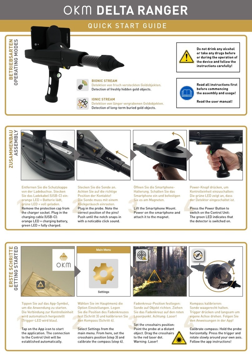
OKM Delta Ranger DR-A01 User manual

SCOPE OF DELIVERY
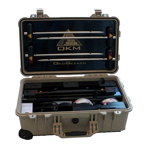
TRANSPORTATION & STORAGE
ASSEMBLY
GETTING STARTED
OPERATIONS
MAINTENANCE
TROUBLESHOOTING
DISPOSAL
TECHNICAL SPECIFICATIONS
REPS & WARRANTIES
USER MANUAL
OKM®Delta Ranger
DETECTOR FOR TREASURE, GOLD AND CAVITY HUNT
MODEL: DRA01
© 2023 OKM GmbH. All Rights Reserved.
U.S. Edition | ENGLISH
Version 1.0 | March 2023

2 / 62
OKM GmbH
Julius-Zinkeisen-Str. 7
04600 Altenburg
Germany
Phone: +49 3447 4993000
Website: www.okmdetectors.com
No part of this document may be reproduced in any form (by printing, photocopying or other means) or processed, duplicated or circulated electronically without prior written approval of OKM GmbH.
Copyright © 2023 OKM GmbH. All rights reserved.
TABLE OF CONTENTS
1 TRANSPORTATION AND STORAGE..........................................5
1.1 AVOID EXTREME TEMPERATURES AND MOISTURE ................................. 5
1.2 CHECK BATTERY STATUS REGULARLY ...................................................... 5
2 SCOPE OF DELIVERY AND CONTROL ELEMENTS ..............7
2.1 CONTROL UNIT ............................................................................................. 8
2.2 ANDROID SMARTPHONE ............................................................................. 9
2.3 CHARGER AND TRAVEL ADAPTER............................................................. 9
2.4 WIRELESS HEADPHONES ........................................................................... 9
2.5 PROBES ......................................................................................................... 9
3 ASSEMBLY ...................................................................................... 11
3.1 NECESSARY TOOLS.....................................................................................11
3.2 ATTACH PROBE............................................................................................11
3.3 ATTACH SMARTPHONE...............................................................................11
3.4 DETACH PROBE ...........................................................................................11
4 GETTING STARTED......................................................................13
4.1 CHARGE INTERNAL BATTERIES ................................................................13
4.2 PREPARE ANDROID DEVICE AND APP......................................................13
4.3 PAIR ANDROID DEVICE WITH DETECTOR.................................................16
4.4 OKM APP INTERFACE .................................................................................16
4.5 PAIR WIRELESS HEADPHONES .................................................................17
4.6 SET CROSSHAIRS POSITION......................................................................17
4.7 CALIBRATE COMPASS ................................................................................18
4.8 SETTINGS.....................................................................................................18
5 OPERATIONS..................................................................................23
5.1 PACEMAKERS ............................................................................................. 23
5.2 CAUTION DURING EXCAVATION................................................................ 23
5.3 OPERATING MODES ................................................................................... 23
5.4 BIONIC STREAM ......................................................................................... 24
5.5 IONIC STREAM.............................................................................................26
5.6 MAGNETOMETER ....................................................................................... 28
5.7 3D GROUND SCAN ...................................................................................... 30
5.8 THERMO SCAN............................................................................................ 38
5.9 THERMO STREAM....................................................................................... 42
5.10 FILE EXPLORER ........................................................................................ 44
5.11 FILE TRANSFER ........................................................................................ 45
6 MAINTENANCE.............................................................................47
6.1 CHECK AND CLEAN CONTROL UNIT AND PROBES.................................47
6.2 CHECK FOR APP UPDATES.........................................................................47
6.3 REGISTER/VERIFY DETECTOR...................................................................47
6.4 MAINTENANCE AND REPAIR BY OKM.......................................................47
7 TROUBLESHOOTING ...................................................................49
8 DISPOSAL .......................................................................................55
9 TECHNICAL SPECIFICATIONS .................................................57
9.1 CONTROL UNIT.............................................................................................57
9.2 PROBES ........................................................................................................57
10 REPS & WARRANTIES..............................................................58
10.1 ACKNOWLEDGEMENTS, REPRESENTATIONS, AND WARRANTIES..... 58
10.2 INDEMNIFICATION.....................................................................................59
10.3 LIMITATION OF LIABILITY.........................................................................59
10.4 SERVICE & SUPPORT ................................................................................59
11 INDEX.............................................................................................. 61
The search for historical and archaeological artifacts and structures
may be regulated in different ways from state to state. Searching with
a detector may require approvals and permissions from landowners,
public agencies and/or government authorities.
With the purchase of the OKM detector you DO NOT automatically
receive a detection permit or excavation permit!
Consult the authorities responsible for your search project and/or
area for information on required permits.
NOTICE
Read all instructions first
before commencing the
assembly and usage!
NOTICE
Do not drink any alcohol
or take any drugs before
or during the operation
of the device and follow
the instructions carefully!
All artifacts found on public lands are protected by state and federal
laws. It is illegal to collect artifacts on public lands. Artifacts include
anything made or used by humans including arrowheads and flakes,
pottery, basketry, rock art, bottles, coins, metal pieces, and even
old cans. Ancient objects that are found on private land are legal for
individuals to collect with written permission from the landowner
and legal for individuals to own under the Native American Graves
Protection and Repatriation Act of 1990 (NAGPRA).
However, these objects could be subject to a civil claim of superior
title by a tribe. Other requirements depend on the state. If you are
interested in collecting or metal detecting on private property, contact
your State Historic Preservation Office for more information.
Before collecting minerals found, familiarize yourself with the rules
stated on the Bureau of Land Management Website for your State.
NOTICE

5 / 624 / 62
1 TRANSPORTATION AND STORAGE
Protect your detector and accessories by storing them in the Protector Case in a cool, dry place
(50 to 75 °F | 10 to 25°C). Unplug the probe from the Control Unit and power off the Control Unit
before packing the device and its accessories into the case.
Use the Protector Case for the intended purpose only. Keep away from children!
CHOKING AND ASPHYXIATION HAZARD!
A Cover is Not a Toy! Keep Away from Children!
DANGER
When shipping, use the original cartboard box or similar heavy-duty container and provide
sufficient padding around all parts.
1.1 AVOID EXTREME TEMPERATURES AND MOISTURE
Protect your device from extreme temperatures as well as dust and moisture during
transportation and storage.
1.2 CHECK BATTERY STATUS REGULARLY
Check the detector regularly if it is not used for a long time. When storing the Delta Ranger for
long periods of time, avoid completely discharging of the batteries. Instead, recharge the battery
at least every 3 months and up to approx. 90 % of the maximum charge capacity.
5 / 62
TRANSPORTATION & STORAGE

7 / 626 / 62
2 SCOPE OF DELIVERY AND CONTROL ELEMENTS
The scope of delivery depends on the selected model version: Light or Professional.
Light Professional
IControl Unit
II Android Smartphone with OKM App
III Charger
IV Travel Adapter
VHeadphones with charging cable
VI Long-Range Probe (L)
VII Thermo Probe (T)
VIII Ground Scan Probe (G)
IX Notebook with OKM Visualizer 3D Studio
XProtector Case
I
II
IIIIV V
VI
VII
VIII
IX
X
SCOPE OF DELIVERY

8 / 62 9 / 62
2.1 CONTROL UNIT
VIII
I
IX
VI
III
II
VII
IV
V
ISmartphone Mount – see 3.3 Attach Smartphone on page 11.
II LED Lighting to illuminate dark areas.
III Probe Fitting with Probe Socket to ensure that the probe is plugged in correctly – see 3.2 Attach Probe on page 11.
IV
Charger Socket (USB-C) to charge the Control Unit with
LED Indicator to show the charging state while charging the internal battery
– see 4.1 Charge Internal Batteries on page 13.
VLabel with device information like Serial Number and Model Number – see 6.3 Register/Verify Detector on page 47.
VI Laser Pointer to set the crosshairs position – see 4.6 Set Crosshairs Position on page 17.
VII Knob to calibrate the Bionic Sensors – see 5.4.1 Calibrate Bionic Sensors on page 24.
VIII Trigger with LED to switch the Control Unit on and off. Control and confirm various functions. The ring-shaped LED indicates 4 connection states:
Flashing Green The Control Unit is switched on and waiting for a connection. No probe is connected and the App is not connected.
Permanently Green The Control Unit is switched on and successfully connected to the probe, but the App is not connected.
Flashing Blue The Control Unit is switched on and connecting/connected to the App, but no probe is connected.
Permanently Blue The Control Unit is switched on and successfully connected to the probe and to the App.
IX Handle with Electrodes – see 5.4.1 Calibrate Bionic Sensors on page 24.
2.2 ANDROID SMARTPHONE
The Control Unit is controlled via an Android smartphone App. For detailed information refer to
the respective sections in this manual. For further settings and information beyond the use of
the OKM App, refer to the smartphone manual.
2.3 CHARGER AND TRAVEL ADAPTER
The Control Unit is charged via charger. For detailed information refer to 4.1 Charge Internal
Batteries on page 13. In some countries the use of the Travel Adapter may be required.
2.4 WIRELESS HEADPHONES
The Android smartphone can be paired with wireless headphones via Bluetooth. For detailed
information refer to 4.5 Pair Wireless Headphones on page 17. For further settings and infor-
mation, refer to the smartphone and headphones manuals respectively.
2.5 PROBES
The OKM Delta Ranger is equipped with various probes according to the acquired edition:
Long-Range
Probe (L)
Thermo
Probe (T)
Ground Scan
Probe (G)
III
I
II
IProbe Label
II Probe Connector
III Notch
For correct assembly see
3.2 Attach Probe on page 11.
2.6 PROTECTOR CASE
The device and its accessories are stored and transported in a Protector Case
see 1 TRANSPORTATION AND STORAGE on page 5. For further information, refer to the
Protector Case Care and Instructions.

11 / 6210 / 62
3 ASSEMBLY
3.1 NECESSARY TOOLS
No additional tools are required to assemble the OKM Delta Ranger.
Do not open the device and/or accessories. There are no end user serviceable parts inside.
3.2 ATTACH PROBE
Probes shall always be attached in the prescribed way matching the Probe Socket Pins.
Make sure the Probe Connector and Socket Pins
are clean before assembly!
NOTICE
Depending on the measurement, attach the probe to the Probe Socket:
1 2
Plug the Probe Connector into the Probe
Socket. Note the correct position of the pins!
Push carefully until the notch snaps in with a
noticable click sound.
3.3 ATTACH SMARTPHONE
3 4
Lift the Smartphone Mount. Attach the smartphone to the magnet.
3.4 DETACH PROBE
1 2
Press and hold the notch of the
Probe Connector to release the Probe.
Pull out the Probe carefully as specified by
the Probe Fitting.
11 / 62
ASSEMBLY

13 / 6212 / 62
4 GETTING STARTED
4.1 CHARGE INTERNAL BATTERIES
Fully charge the Control Unit and the smartphone.
To charge the internal batteries, connect the charger from the power sup-
ply to the designated
Charger Socket. Use the Travel Adapter to enable
a connection between the charger and a non-compatible wall socket.
The charging progress is indicated by the LED light next to the Charger
Socket: Orange when charging, and Green when fully charged.
It can take up to 4 hours to fully charge the battery.
1 2
Locate the Charger Socket. Remove the protection cap.
3 4
Plug in the Charging Cable (USB-C). Charge the smartphone via charging cable.
4.2 PREPARE ANDROID DEVICE AND APP
The OKM Delta Ranger is by default equipped with a pre-configured Android smartphone with
pre-installed and activated OKM Delta Ranger App.
You may install and activate the OKM App if:
• you want to use your own Android device.
• you want to add further Android devices.
• you reset the pre-configured Android device.
• you have technical problems with the OKM App.
4.2.1 Download and Install OKM App
The OKM Delta Ranger App is usually pre-installed on the included Android smartphone.
Browse the Apps in your smartphone to make sure the required OKM App has not yet been
installed.
• Get the Download File from the OKM online store or contact OKM Support.
• Download the OKM App to the Android device.
• Install the OKM App on the Android device.
• After successful installation, start the App, select Settings from the main menu and start
Update by tapping on the icon.
• After successful update, restart the App and proceed with the Activation – see
4.2.2 Activate OKM App on page 14.
GETTING STARTED

14 / 62 15 / 62
4.2.2 Activate OKM App
2
If you have problems using the QR Code or you
do not have a QR Code, select Manual.
3
Enter the OKM Delta Ranger Serial Number.
4
Enter the OKM Delta Ranger Activation Code.
1
Select Activate App from the Settings menu.
2
If you have received a QR Code from OKM for
an automatic activation, select QR Code.
3
Use the smartphone camera to scan the
QR Code that you received with the detector.
5
Confirm the activation by tapping on
If the activation failed, try again. Make sure
that all entered data are correct.

16 / 62 17 / 62
4.3 PAIR ANDROID DEVICE WITH DETECTOR
1 2
Press the trigger to power on the Control Unit.
Power on the smartphone. Tap on the OKM
Delta Ranger App icon to start the application.
The App automatically establishes a connection to the Control Unit, if activated correctly.
4.4 OKM APP INTERFACE
I
X
II III
IV
V
VI
VII
VIII
IX
IMenu Icon shows the active menu. Tap to return to the main menu.
II The headline shows the active menu or option.
III App Connection Status indicates the connection status between App and
Control Unit.
not connected
connecting
connected
IV LED Lighting: Tap on the icon to toggle between ON and OFF:
OFF (default)
ON
VSmartphone Battery Status
battery level
VI Control Unit Battery Status
battery level
critical
charging
unknown
VII Language Code shows the selected language – see 4.8.1 Language on page 19.
VIII Navigation Sidebar: Tap on the arrows to browse through the options.
The dots indicate the number of available options.
IX Selectable Option: Tap on the icon to enter the menu or launch the option.
XReturn to the previous menu.
4.5 PAIR WIRELESS HEADPHONES
The acoustic feedback of the detector can be provided by headphones instead of smartphone
speakers in order to avoid attracting attention. Connect wireless headphones by pairing with
the smartphone:
Settings > Connected devices > Pair new device > Available devices > [Bluetooth Headphones]
Baseline HS
These settings may vary from one smartphone to another. Refer to your smartphone manual if
you have trouble pairing headphones.
4.6 SET CROSSHAIRS POSITION
LASER RADIATION
Avoid Direct Eye Exposure!
DANGER
Crosshairs Calibration is used to align the reticle (crosshairs) on the smartphone screen with
the laser dot on a distant object. This calibration is recommended before performing a new
measurement and every time you have changed the smartphone position on the Control Unit.
Make sure you have powered on the Control Unit and plugged in the Long-Range Probe (L) or
Thermo Probe (T).
1 2
Select Settings from the main menu and tap
on the Crosshairs Calibration icon.
The laser pointer is enabled as soon as you
confirm with .
34
Point the probe at a distant object so that you
can clearly see the red laser dot.
Drag the crosshairs to the correct position
on the smartphone screen: Center the cross-
hairs on the red laser dot. Confirm with .

18 / 62 19 / 62
4.7 CALIBRATE COMPASS
Compass Calibration ensures that the cardinal directions are displayed correctly. This cali-
bration is recommended every time you have restarted the detector. Keep at least 160 ft (50 m)
distance from ferromagnetic interferences (e.g. power lines, electric fence).
1 2
Select Settings from the main menu and tap
on the Compass Calibration icon.
Make sure to hold the Control Unit
horizontally.
34
Press the trigger and rotate slowly around
your own axis ...
... while the calibration screen is visible.
Avoid pivoting or swinging during calibration.
56
After completing your 360° rotation,
finish the successful calibration with ...
... or retry the calibration.
4.8 SETTINGS
The following preferences and configurations are available via the Settings menu:
Language see 4.8.1 Language on page 19
Sound see 4.8.2 Sound on page 19
Vibration see 4.8.3 Vibration on page 19
GPS see 4.8.4 GPS on page 19
App Theme see 4.8.5 App Theme on page 20
Length Unit see 4.8.6 Length Unit on page 20
Temperature Unit see 4.8.7 Temperature Unit on page 20
Crosshairs Calibration see 4.6 Set Crosshairs Position on page 17
Compass Calibration see 4.7 Calibrate Compass on page 18
Activation see 4.2.2 Activate OKM App on page 14
Update see 6.2 Check for App Updates on page 47
4.8.1 Language
Use the buttons to loop through the
available languages. The selection is auto-
matically applied as soon as you return to the
previous menu by tapping or proceed to
the next settings option by tapping .
The selected language is indicated in the toolbar with the 2-letter-code according to ISO-639-1:
عربي (AR)
български (BG)
Deutsch (DE)
Ελληνικά (EL)
English (EN)
Español (ES)
فارسی (FA)
Français (FR)
Italiano (IT)
日本語 (JA)
Polski (PL)
Русский (RU)
Türkçe (TR)
中文 (ZH)
4.8.2 Sound
The App provides acoustic feedback for various functions. Tap on the switch to toggle between ON
and OFF. To avoid attracting attention you may use Bluetooth headphones (see 4.5 Pair Wireless
Headphones on page 17) or select Sound OFF.
VOLUME is adjusted via smartphone volume control buttons or Settings > Sound > Media Vol-
ume.
TOUCH SOUNDS are adjusted via smartphone: Settings > Sound > Advanced > Touch sounds.
These sound settings may vary from one smartphone to another. Refer to your smartphone's
manual if you have trouble adjusting the volume and touch sounds.
4.8.3 Vibration
Tap on the switch to toggle between ON and OFF.
The operating modes Bionic Stream, Ionic Stream, and Magnetometer provide vibration
feedback (via smartphone).
4.8.4 GPS
GPS coordinates can be logged for 3D Ground Scan and Thermo Scan, and will be saved as scan
file Meta Data for further documentation in the Visualizer 3D Studio software. Tap on the switch
to toggle between ON and OFF.

20 / 62 21 / 62
4.8.5 App Theme
Tap on the switch to toggle between Day Mode and Night Mode.
Day Mode is recommended in very bright environments. Night Mode is recommended in dark
conditions and allows to remain inconspicuous in the dark.
4.8.6 Length Unit
Tap on the switch to toggle between Imperial and Metric.
Imperial indicates all dimensions in feet (ft). Metric indicates all dimensions in meters (m).
4.8.7 Temperature Unit
Tap on the switch to toggle between °Fahrenheit and °Celcius.
NOTES

23 / 6222 / 62
5 OPERATIONS
5.1 PACEMAKERS
OKM Delta Ranger is a passive measuring instrument that does not emit magnetic waves.
Clarify possible interferences with your medical doctor if you are wearing a pacemaker or
similar medical device.
Magnetic fields and metallic objects influence the scan results. Keep the detector at least
160 ft (50m) away from magnetic fields, electric motors, speakers, phones, keys, and jewelry.
Remove visible metallic objects such as cans, nails, screws or debris from your scan field
before performing measurements with the detector.
5.2 CAUTION DURING EXCAVATION
Do not touch detected ammunition!
Report it to the police!
DANGER
Once you get a clear target signal, excavate the area around the target object carefully to pre-
vent damage to a potential rare find and minimize the possibility of accidentally detonating old
ammunition.
Note the color of the soil close to the surface: A reddish color can be an indicator of rust trace
of various kinds of fuses.
Pay attention to the shape of target objects: Curved or round objects can be coins or wedding
bands, but may also be parts of ammunition. If you identify buttons, rings or little pegs, excavate
particularly carefully.
5.3 OPERATING MODES
The following operating modes are available in the OKM Delta Ranger App:
Bionic Stream see 5.4 Bionic Stream on page 24
Ionic Stream see 5.5 Ionic Stream on page 26
Magnetometer see 5.6 Magnetometer on page 28
3D Ground Scan see 5.7 3D Ground Scan on page 30
Thermo Scan see 5.8 Thermo Scan on page 38
Thermo Stream see 5.9 Thermo Stream on page 42
File Explorer see 5.11 File Transfer on page 45
The operating modes are activated as soon as the correct probe is connected.
OPERATIONS

24 / 62 25 / 62
5.4 BIONIC STREAM
Use the operating mode Bionic Stream to detect recently buried gold objects, long-time buried
gold as well as golden artifacts that are buried at long distances.
Make sure you have plugged in the Long-Range Probe (L).
This operating mode allows horizontal probe orientation.
5.4.1 Calibrate Bionic Sensors
1 2
Start the operating mode Bionic Stream by
tapping on the option in the App main menu.
Grasp the handle with your leading hand.
Make sure that palm and fingers touch the
electrodes.
34
With the other hand, turn the Knob very
gently to calibrate the Bionic sensors.
Set a value within the green range - ideally
reach the highest possible value close to
254. Make sure to keep the value stable for at
least 3 seconds. Confirm with .
If contact to the electrodes is lost during calibrating or measuring, repeat the calibration by
tapping on .
5.4.2 Measurement Screen
Enable the laser pointer for 5 s as an additional tool for aiming at the target object.
You may correct the crosshairs position via Settings – see 4.6 Set Crosshairs Posi-
tion on page 17.
Change Reticle (crosshairs): Tap to change the reticle design.
Choose from 5 different options. Your choice is saved automatically.
Recalibrate Bionic Sensors, see 5.4.1 Calibrate Bionic Sensors on page 24.
Exit Bionic Stream and return to the main menu.
Before performing a measurement, make sure you have set the crosshairs position according to
your planned scan zone. You may recalibrate the crosshairs whenever you like.
5.4.3 Perform Triangulation Measurement
Triangulation (or Cross Bearing) uses two or more points simultaneously to fix a position. This procedure helps to determine a potential target spot more precisely and to verify detected target spots.
1 2 3 4
Hold the Probe horizontally. Scan the area from the first position. Move the Probe slowly from side to side ... ... as well as up and down.
5 6 7 8
A hit is signaled by:
• acoustic feedback (if Sound is enabled)
• vibration (if Vibration is enabled)
• visual feedback (flashy crosshairs)
Perform a Control Scan from a different
direction at about 80 to 1600 ft (25 to 500 m)
distance from your first spot.
Before proceeding with the measurement,
you may recalibrate the crosshairs position –
see 4.6 Set Crosshairs Position on page 17
– and the Bionic Sensors – see 5.4.1 Calibrate
Bionic Sensors on page 24.
As soon as you get a hit on the same target
spot, it is likely it is a potential target.
You may perform further control scans to
verify the target spot.

26 / 62 27 / 62
5.5 IONIC STREAM
Use the operating mode Ionic Stream to detect gold objects that have been buried for a long time.
Make sure you have plugged in the Long-Range Probe (L).
This operating mode allows horizontal probe orientation.
5.5.1 Calibrate Ionic Sensors
1 2
Start the Operating Mode Ionic Stream by
tapping on the option in the App main menu.
Place a reference object – an object made
of the same material you are looking for – in
front of you. Aim at it with the probe heading
to the North.
4“
10cm
34
Keep a distance of about 4" (10cm) between
the tip of the probe and the reference object.
Confirm by tapping on the focus zone
(alternatively by pressing the trigger
or tapping on ).
Keep aiming at the object and wait until the
countdown has finished.
5.5.2 Measurement Screen
Enable the laser pointer for 5 s as an additional tool for aiming at the target object.
You may correct the crosshairs position via Settings – see 4.6 Set Crosshairs Posi-
tion on page 17.
Change Reticle (crosshairs): Tap to change the reticle design.
Choose from 5 different options. Your choice is saved automatically.
Recalibrate Ionic Sensors, see 5.5.1 Calibrate Ionic Sensors on page 26.
Exit Ionic Stream and return to the main menu.
Before performing a measurement, make sure you have set the crosshairs position according to
your planned scan zone. You may recalibrate the crosshairs whenever you like.
5.5.3 Perform Triangulation Measurement
Triangulation (or Cross Bearing) uses two or more points simultaneously to fix a position. This procedure helps to determine a potential target spot more precisely and to verify detected target spots.
1 2 3 4
Move the probe slowly from side to side ... ... as well as up and down. For best measurement results, scan into the
natural ion stream of the geomagnetic field:
always pointing to the South, Southeast or
Southwest.
Measure perpendicular to the ground. Avoid
pointing the detector too high or too low.
5 6 7 8
A hit is signaled by:
• acoustic feedback (if Sound is enabled)
• vibration (if Vibration is enabled)
• visual feedback (flashy crosshairs)
Perform a Control Scan from a different
direction at about 80 to 1600 ft (25 to 500 m)
distance from your first spot.
Before proceeding with the measurement,
you may recalibrate the crosshairs position.
As soon as you get a hit on the same target
spot, it is likely it is a potential target.
You may perform further control scans to
verify the target spot.

28 / 62 29 / 62
5.6.3 Perform Measurement
1
Hold the probe vertically.
Move the detector back and forth ...
... but keep the orientation of the probe
parallel to your starting orientation.
2
Move the detector to the sides ... ... but do not pivot, swing or rotate the probe.
34
If the signal becomes unstable, point
the probe to a neutral (non-ferrous and
non-magnetic) surface ...
... and press the trigger or tap on to
perform a Ground Balance. The bar graph is
immediately reset to the zero line.
In Ferro Pointer View, tap on or press
the trigger to reset the indicator.
5.6.4 Interpret Measurement
Magnetometer provides
• acoustic feedback (if Sound is enabled),
• vibration feedback (if Vibration is enabled) and
• a basic visual representation.
As soon as you get a clear signal, the device has detected a potential metal target in front of
(horizontal measurement) or below (vertical measurement) the probe respectively.
As soon as the probe is very close to the detected object, the values reach its peak and indicate
a hit with vibration.
The bar graph shows BLUE
peaks if the probe is pointing
at the negative magnetic
pole of a ferrous object.
The bar graph is in the
GREEN range (close to zero
line) if there is no ferrous or
magnetic target object.
The bar graph shows RED
peaks if the probe is pointing
at the positive magnetic pole
of a ferrous object.
The indicator is in the BLUE
zone if the probe is pointing
at the negative magnetic
pole of a ferrous object.
The indicator is in the GREEN
zone if there is no ferrous or
magnetic target object.
The indicator is in the RED
zone if the probe is pointing
at the positive magnetic pole
of a ferrous object.
5.6 MAGNETOMETER
Use the operating mode Magnetometer to detect small metal objects like nails, screws and
wires made of ferromagnetic materials such as iron, nickel and cobalt close to the surface. Re-
move these items from the scan field before performing further scans!
The fewer small metal items in the soil, the deeper you can detect targets with 3D Ground Scan.
Moreover, use Magnetometer to pinpoint objects during excavation.
Make sure you have plugged in the Ground Scan Probe (G).
This operating mode allows vertical and horizontal (short-range)
probe orientation.
5.6.1 Prepare Measurement
1 2
Point the probe to a neutral (non-ferrous and
non-magnetic) surface.
Start the operating mode Magnetometer by
tapping on the option in the App main menu.
5.6.2 Measurement Screen
Magnetometer View (default) Ferro Pointer View
Switch to Ferro Pointer View. Switch to Magnetometer View.
Perform a Ground Balance: Point
the probe to a neutral (non-ferrous
and non-magnetic) surface and tap
on the icon to reset the bar graph.
Perform a Ground Balance: Point
the probe to a neutral (non-ferrous
and non-magnetic) surface tap on
the icon to reset the indicator.
Change the Sensor Sensitivity: Tap to switch between
low
medium
high
Set low sensitivity when using Magnetometer on rough terrain or
on scan fields with high mineralization.
Exit Magnetometer and return to the main menu.

30 / 62 31 / 62
2
Select Customized to adjust the parameters
individually.
3
Auto: The length is determined by pressing
the trigger at the end of the first scan line.
1
Start the operating mode 3D Ground Scan by
tapping on the option in the App main menu.
2
Select Default to use the preset parameters
for fast scans.
6
Confirm by tapping on Start Scan.
Set the Field Length by tapping on +and -.
3
1ft ... 160 ft: The length is defined before the
scan. All lines will stop automatically.
Toggle to set the Impulse Mode.
4
Automatic: The impulses (scan values) will
be recorded continuously without any break.
4
Manual: Every single impulse (scan value) is
recorded by pressing the trigger.
5
Parallel: Scan all lines in the same direction.
5
Zigzag: Scan all scan lines forwards and
backwards alternately.
Toggle to set the Scan Mode.
6
Confirm by pressing Start Scan.
8
Continue with section
5.7.2 Perform Default 3D Ground Scan on
page 32,
5.7.3 Perform Zigzag 3D Ground Scan on
page 34 or
5.7.4 Perform Manual 3D Ground Scan on
page 36.
Ready to start your 3D Ground Scan.
7
Searching for a GPS Signal (if enabled).
5.7 3D GROUND SCAN
Use the operating mode 3D Ground Scan to get a detailed visualization of underground
structures and potential target objects for further analysis in Visualizer 3D Studio.
Learn more in the 3D Ground Scan Guide.
5.7.1 Configure Measurement
Make sure you have connected the Ground Scan Probe (G).
This operating mode allows vertical and horizontal (short-range)
probe orientation.

32 / 62 33 / 62
5.7.2 Perform Default 3D Ground Scan
The default parameters Field Length: Auto | Impulse Mode: Automatic | Scan Mode: Parallel
are recommended for entry-level detector users and allow scanning in slightly sloping terrain.
3
Return to your first starting point without
scanning and take one step to the left: This
is the starting point of the second scan line.
1
Go to the starting point of the first scan line
(bottom right corner).
Press the trigger to start scanning. Start
walking as soon as you press the trigger.
2
Walk to the end of the first scan line. Press
the trigger as soon as you reach its end
to set the field length for the following lines.
The scan image will be generated line by
line to help you to follow your progress while
measuring.
The first scan lines may initially look incor-
rect. However, the inconsistent scan image
will stabilize in the course of the scan.
6
Complete the measurement by tapping on
Finish Scan .
Confirm saving with or discard the scan
with .
4
Press the trigger to start scanning. Start
walking as soon as you press the trigger.
Walk parallel to your first scan line and at the
same speed. The impulse sound should stop
at the end of the line.
7
If you chose to save the scan, enter the Field
Length and Field Width that you actually
measured.
8
The scan file is opened in the File Explorer –
see 5.10 File Explorer on page 44.
5
Return to the last starting point and take a
step to the left (without scanning): This is the
starting point of the next scan line.
Press the trigger to start scanning and walk
at the same speed until you reach the end of
the scan line.
Repeat this to scan as many lines as you like.

34 / 62 35 / 62
5.7.3 Perform Zigzag 3D Ground Scan
The parameters Field Length: Individual | Impulse Mode: Automatic | Scan Mode: Zigzag
are recommended for advanced detector users and can be applied in flat terrain.
3
Remain at the end of the scan line and take
a step to the left (without scanning). Keep
holding the probe in the same direction as in
the first scan line.
1
Go to the starting point of the first scan line
(bottom right corner).
Press the trigger to start scanning. Start
walking as soon as you press the trigger.
2
Walk the first line at a constant speed. The
App stops recording values automatically as
soon as reaching the preset field length and
indicates this by a noticeable sound signal.
The scan image will be generated line by
line to help you to follow your progress while
measuring.
The first scan lines may initially look incor-
rect. However, the inconsistent scan image
will stabilize in the course of the scan.
6
Complete the measurement by tapping on
Finish Scan .
Confirm saving with or discard the scan
with .
4
Press the trigger to start scanning. Walk
parallel to your first scan line but in reverse
until you reach the end of the scan line.
Walk at the same speed as in the first scan
line. The impulse sound should stop as soon
as you reach the end of the line.
In Scan Mode Zigzag all scan lines are
scanned by walking forwards and back-
wards. However, the scan lines shall still be
parallel to each other and the probe shall
always point in the same direction.
7
If you chose to save the scan, check and
correct/confirm the preset Field Length and
enter the Field Width.
8
The scan file is opened in the File Explorer –
see 5.10 File Explorer on page 44.
5
Remain at the end of the scan line and take a
step to the left (without scanning).
Press the trigger to start scanning. Walk
parallel to the first scan line (forwards) and
at the same speed until you reach the end of
the scan line.
Repeat steps 3 to 5 to scan as many lines as
you like: Odd scan lines forwards, even scan
lines backwards.
Follow the App instructions to scan in the
correct direction.

36 / 62 37 / 62
5.7.4 Perform Manual 3D Ground Scan
The parameters Field Length: Auto | Impulse Mode: Manual | Scan Mode: Parallel
are recommended for rough terrain.
3
Return to your first starting point without
scanning and take one step to the left: This
is the starting point of the second scan line.
Press the trigger to record the first impulse
of your second scan line.
1
Go to the starting point of the first scan line
(bottom right corner).
When using Impulse Mode Manual each
single impulse (scan value) is released
manually one by one by pushing the trigger.
2
Press the trigger to start the measurement.
Take a step forward and press the trigger
again to record an impulse.
Continue in this way until you reach the end
of the first scan line. Tap on Finish Scan Line
to set the field length.
The scan image will be generated line by
line to help you to follow your progress while
measuring.
The first scan lines may initially look incor-
rect. However, the inconsistent scan image
will stabilize in the course of the scan.
6
Complete the measurement by tapping on
Finish Scan .
Confirm saving with or discard the scan
with .
4
Take a step forward and press the trigger
again to record the next impulse. Continue
until you reach the end of the scan line.
Scan parallel to your first scan line with the
probe heading into the same direction as in
the first scan line.
The App indicates the end of the scan line.
7
If you chose to save the scan, enter the Field
Length and Field Width that you actually
measured.
8
The scan file is opened in the File Explorer –
see 5.10 File Explorer on page 44.
5
Return to the last starting point and take a
step to the left (without scanning): This is the
starting point of the next scan line.
Press the trigger to start scanning. Release
an impulse at each step forward until you
reach the end of the scan line.
Repeat this to scan as many lines as you like.

38 / 62 39 / 62
2
Select Customized to adjust the parameters
individually.
3
Auto: The length is determined by pressing
the trigger at the end of the first scan line.
1
Start the operating mode Thermo Scan by
tapping on the option in the App main menu.
2
Select Default to use the preset parameters
for fast scans.
6
Confirm by pressing Start Scan.
Set the Field Length by tapping on +and -.
3
1ft ... 160 ft: The length is defined before the
scan. All lines will stop automatically.
Toggle to set the Impulse Mode.
4
Automatic: The impulses (scan values) will
be recorded continuously without any break.
4
Manual: Every single impulse (scan value) is
recorded by pressing the trigger.
5
Parallel: Scan all lines in the same direction.
5
Zigzag: Scan all scan lines forwards and
backwards alternately.
Toggle to set the Scan Mode.
6
Confirm by pressing Start Scan.
8
Continue with section 5.8.2 Perform Zigzag
Thermo Scan on page 40.
Ready to start your Thermo Scan.
7
Searching for a GPS Signal (if enabled).
5.8 THERMO SCAN
Use the operating mode Thermo Scan to visualize hidden structures such as rooms, caves and
tunnels based on noticeable temperature deviations of surfaces. These visualizations allow
further analyses in Visualizer 3D Studio.
5.8.1 Configure Measurement
Make sure you have connected the Thermo Probe (T).
This operating mode allows horizontal (short-range) and vertical
probe orientation.
Table of contents
Other OKM Security Sensor manuals