manuals.online logo
Brands
  1. Home
  2. •
  3. Brands
  4. •
  5. Visonic
  6. •
  7. Security Sensor
  8. •
  9. Visonic CH-1000 User manual

Visonic CH-1000 User manual

DE1100 1
CH
CHCH
CH-1000
-1000-1000
-1000
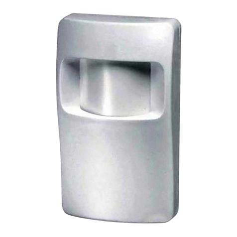
Curtain Passive Infra-Red Detector Installation Instructions
1
11
1. INTRODUCTION
. INTRODUCTION. INTRODUCTION
. INTRODUCTION
The CH-1000 curtain provides solid curtain coverage of maximum
13.5 m length x 6 m height (45 ft x 20 ft).
The CH-1000 may be used for perimeter protection, by setting up
motion detection "curtains” along walls, large show windows,
skylights and ceilings. It can also be used as an internal invisible
barrier to detect movement between two adjacent areas. The
CH-1000 can be mounted on the wall or on the ceiling.
A unique calibrated scale enables
horizontal pattern adjustment of
+7°to the left or to the right.
A double polarity, programmable
pulse counter provides maximum
immunity against environmental
disturbances.
2
22
2. COVERAGE PATTERNS
. COVERAGE PATTERNS. COVERAGE PATTERNS
. COVERAGE PATTERNS
Various mounting alternatives
are available, each of which
provides different coverage
patterns as a solid curtain:
A. Wall Mounted (Figure 1)
The unit should be mounted on
the wall at a maximum height of
6.0 m (20 ft). It provides solid
curtain coverage, extending out
from the mounting wall to the
opposite wall up to a maximum
distance of 13.5 m (45 ft) and
down to the floor. The unit must
be mounted horizontally, with
the lens pointed downward,
toward the floor. Figure 1. Wall Mounted Curtain
C. Pet Alley (Figure 3)
Pet-alley curtain can be created
by installing the CH-1000 on the
wall, near the floor, with the lens
pointed toward the ceiling.
D. Skylight (Figure 4)
This method is useful for
detection of entry through the
ceiling or skylights. Install the unit
as close as possible to the ceiling
area or skylights to be protected
and close to a corner of the
protected area
Note:Maintain a minimum
vertical distance of 0.5 m (1.5 ft)
from the ceiling or skylights.Figure 3. Pet Alley Curtain
B. Ceiling Mounted (Figure 2)
The unit is mounted on the
ceiling at a maximum height of
6.0 m (20 ft). It provides solid
curtain coverage, extending
down to the floor and away from
the unit up to a maximum
distance of 13.5 m (45 ft).
The unit must be mounted with
the lens pointed towards the
desired direction of the curtain
coverage.
Figure 2. Ceiling Mounted Curtain
The unit is installed with its long
axis vertical, so that the coverage
pattern will be parallel to the floor
(rotated 90°from the wall
mounted installation - see Fig. 1).
The maximum coverage of this
installation is 5 x 5 m (17 x 17 ft).
The field of view is 90°extending,
from the unit toward the opposite
wall and along the wall on which
the unit is mounted in the
direction that the lens is facing.
Figure 4. Skylight Solid Curtain
3
33
3. SPECIFICATIONS
. SPECIFICATIONS. SPECIFICATIONS
. SPECIFICATIONS
OPTICAL
Detection Patterns:
Solid Curtain with maximum coverage pattern of 13.5 m length
and 6 m height (45 x 20 ft). Other patterns see above.
Adjustment: Horizontal ±7°calibrated to the left or right side.
ELECTRICAL
Voltage: 9 to 16 VDC.
Current:20 mA.
Relay Output: Normally closed (tail safe) contacts. 18 ohm
resistor in series with contacts. Rating - 0.1A resistive 30 VDC.
Alarm Period: 2-5 seconds.
Tamper Contacts: Normally closed. Rating - 0.5A resistive/
30 VDC.
LED: Walk Test - Enabled or disabled with internal link.
Detector: Dual-element low noise pyroelectric detector.
Pulse Counter: A selector for 1 / 2 pulses with opposite polarity.
MOUNTING
Wall or ceiling mounting.
ENVIRONMENTAL
Operating Temperature: 0°to 49°C (32°F to 120°F).
Storage Temperature: -20°to 60°C (-4°F to 140°F).
PHYSICAL
Dimensions: 105 x 65 x 53 mm (4.1 x 2.5 x 2.1 in.).
Weight: 90 g (3.2 oz)
Color: Soft White.
MODELS AVAILABLE
CH-1000: Standard model
CH-1000S: Same as CH-1000, but with Form-1C relay contacts.
2DE1100
4
44
4. INSTALLATION
. INSTALLATION. INSTALLATION
. INSTALLATION
4.1 Mounting
The CH-1000 PIR can be installed on the wall or on the ceiling,
according to the specific application as described in Section 1.
The maximum mounting height is 6 m (20 ft).
A. Select the mounting location so that the expected motion path of
an intruder will cross the curtain pattern. Refer to Section 2 for a
detailed description of the mounting alternatives and their
respective coverage patterns.
Note: Passive infrared detectors are sensitive to changes in
infrared energy caused by an object moving across the unit's
field of view. Under certain temperature and background
conditions, in which the temperature difference is too small, the
PIR may fail to respond. It is therefore recommended that the
PIR be aimed toward the coolest place in the protected area, in
order to obtain the maximum sensitivity.
B. Select the mounting height according to the maximum required
coverage range. For maximum sensitivity do not install the
CH-1000 higher than necessary. For normal applications it is
recommended to install the unit between 2.7 and 3 m height (9 to
12 ft).
C. With CH-1000 pet-alley coverage pattern, it is recommended that
the sensor be installed at the lowest possible height that still
enables the pets to move below the curtain pattern without being
detected.
D. CH-1000 is extremely immune to air turbulence and RFl.
However, to minimize possible false alarms, it is highly
recommended to avoid aiming the detector at heaters, sources of
light, or windows subjected to direct sunlight. Also avoid running
wiring close to high power electrical cables.
E. Open the cover by gently
inserting a quarter-inch screw-
driver in the slot at the bottom
of the unit, between the front
cover and the base. Twist the
screwdriver slightly until the
cover swings outward and
removes easily. Figure 5. Removing the Cover
F. Mount the base (equipped with the printed circuit board) in the
location and height selected for optimum coverage. Use the two
elongated mounting holes at the back of the base. The unit must
be fastened firmly to the mounting surface to avoid possible
vibrations.
4.2 Wiring
Route the wires into the detector
via the wiring knockouts. See
Figure 7.
Connect wires to the terminal
block in the following order.
Refer to Figure 6.
* Model CH-1000S only Figure 6. Terminal Block
A. Connect the Tamper N.C. terminals to a normally closed 24-hour
protection zone of the control panel. Tamper contact will open
when cover is removed.
B. Connect the Relay N.C. terminals to a normally closed burglar
protection zone of the control panel. Relay contacts will open
when a motion is detected or during power loss. The relay
contacts are rated at 100 mA, 30 VDC maximum (resistive load
only). An 18 ohm resistor is internally connected in series with the
relay contacts.
Note: Model CH-1000S provides changeover Form-1C relay
contacts (i.e. N.C. + N.O.).
C. Connect the 12 VDC (+) and (–) terminals to a 9 to 16 Volt DC
power source and check for correct polarity. It is advisable that
the power supply be battery backed-up. The current drain of each
sensor is approximately 20 mA.
Figure 7. Printed Circuit Board
4.3 Curtain Adjustment
The calibrated adjustment scale (printed on the left corner of the p.c.
board) and the plastic pointer on the base indicate in degrees the
approximate horizontal angle between the center line of the unit and
the direction of the curtain pattern.
The scale enables fast and easy adjustment of the curtain to the left
or to the right of about 7°in either direction.
As shipped, all CH-1000 detectors are factory-preset to 0°. To
change the horizontal pattern adjustment, loosen the screw which
fastens the printed circuit board to the base. Slide the p.c. board to
the left or to the right as desired and tighten the screw firmly.
The markings "left" and "right" on the p.c. board indicate the
direction of the pattern adjustment, relative to the unit, as viewed
from the unit in the direction of the curtain pattern.
4.4 Setting the Pulse Counter
The CH-1000 is equipped with a selectable pulse counter which can
be set to count two consecutive pulses with opposite polarity, before
activating the alarm relay. This pulse counter logic requires that the
moving person will cross both sides of the curtain pattern, which
correspond to the two elements of the dual detector. This provides
maximum protection against false alarms caused by environmental
disturbances.
A. 2-pulse setting: The two-pulse logic may be selected only when
the CH-1000 is installed in cold or temperature- controlled
locations and where the installation height is less than 3.6 m
(12 ft) and the required coverage range is less than 9.0 m (30 ft).
Otherwise, one pulse should be selected.
B. 1-pulse setting: This setting actually disables the pulse counter.
It should be used when maximum detecting sensitivity or fast
"catch" performance are of highest importance, such as in high
security installations.
4.5 Walk Test
A. Apply 12 VDC power and allow five minutes for the unit to warm
up and stabilize before testing.
B. Adjust the curtain position as explained in Para. 4.3.
C. Set the pulse counter per Para. 4.4 above.
D. Walk-test the coverage area by crossing the curtain from one
side to the other (in opposite directions) and observe the LED.
The LED lights up whenever the unit detects your motion. Allow
10 seconds between each test for the unit to stabilize. Repeat the
test in various locations and distances from the detector up to the
far end of the desired coverage range.
E. After testing, the LED can be disabled to prevent unauthorized
persons from tracing the coverage pattern. To disable the LED,
set the jumper marked "LED" to the OFF position.
NOTE: The range and the coverage area should be checked by an
alarm technician at least once a year. To assure proper continuous
functioning, the user should be instructed to perform a walk test at
the far end of the coverage pattern to assure an alarm signal prior to
each time the alarm system is armed.
VISONIC LTD (ISRAEL): P.O.B 22020 TEL-AVIV 61220 ISRAEL. PHONE: (972-3) 645-6789, FAX: (972-3) 645-6788
VISONIC INC. (U.S.A.): 10 NORTHWOOD DRIVE, BLOOMFIELD CT. 06002-1911. PHONE: (860) 243-0833, (800) 223-0020 FAX: (860) 242-8094
VISONIC LTD. (UK): UNIT 1, STRATTON PARK, DUNTON LANE BIGGLESWADE, BEDS. SG18 8QS. PHONE: (01767) 600857 FAX: (01767) 601098
INTERNET: www.visonic.com
©VISONIC LTD. 2001 CH-1000 D-1100-0 NEW: DE1100- (REV. 4, 8/01) Refer to a separate warranty statement
Other Visonic Security Sensor manuals

Visonic TOWER CAM PG2 User manual

Visonic

Visonic TOWER CAM PG2 User manual

Visonic DISCOVERY QUAD MCW User manual

Visonic

Visonic DISCOVERY QUAD MCW User manual

Visonic DISCOVERY PIR MCW User manual

Visonic

Visonic DISCOVERY PIR MCW User manual

Visonic GLASSTECH User manual

Visonic

Visonic GLASSTECH User manual

Visonic DUO 240 - INSTALLER GUIDE User manual

Visonic

Visonic DUO 240 - INSTALLER GUIDE User manual

Visonic MCPIR-2000 User manual

Visonic

Visonic MCPIR-2000 User manual

Visonic MP-802 K9-85 PG2 User manual

Visonic

Visonic MP-802 K9-85 PG2 User manual

Visonic MCPIR-3000 User manual

Visonic

Visonic MCPIR-3000 User manual

Visonic DUET-AM C/O User manual

Visonic

Visonic DUET-AM C/O User manual

Visonic NEXT PG2 - User manual

Visonic

Visonic NEXT PG2 - User manual

Visonic MCT-441 User manual

Visonic

Visonic MCT-441 User manual

Visonic MCT-441 User manual

Visonic

Visonic MCT-441 User manual

Visonic DUET User manual

Visonic

Visonic DUET User manual

Visonic MCM-140 User manual

Visonic

Visonic MCM-140 User manual

Visonic GSD-441 PG2 User manual

Visonic

Visonic GSD-441 PG2 User manual

Visonic MCT-302 User manual

Visonic

Visonic MCT-302 User manual

Visonic MC-302V PG2 User manual

Visonic

Visonic MC-302V PG2 User manual

Visonic SRN-2000 SERIES User manual

Visonic

Visonic SRN-2000 SERIES User manual

Visonic NEXT PIR MCW User manual

Visonic

Visonic NEXT PIR MCW User manual

Visonic SPD-1000 User manual

Visonic

Visonic SPD-1000 User manual

Visonic NEXT DUO User manual

Visonic

Visonic NEXT DUO User manual

Visonic TOWER 40 User manual

Visonic

Visonic TOWER 40 User manual

Visonic TOWER-20AM PG2 User manual

Visonic

Visonic TOWER-20AM PG2 User manual

Visonic DISCOVERY PIR MCW - INSTALLER GUIDE User manual

Visonic

Visonic DISCOVERY PIR MCW - INSTALLER GUIDE User manual

Popular Security Sensor manuals by other brands

FDD CR 135-2C installation instructions

FDD

FDD CR 135-2C installation instructions

Bosch FCA-350-B4 Installation and maintenance instructions

Bosch

Bosch FCA-350-B4 Installation and maintenance instructions

Duramaxx Powerpoint manual

Duramaxx

Duramaxx Powerpoint manual

KRAUSE ProTec Instructions for assembly

KRAUSE

KRAUSE ProTec Instructions for assembly

Honeywell Home Resideo PROSIXPIR installation instructions

Honeywell Home

Honeywell Home Resideo PROSIXPIR installation instructions

Alpina 871125226550 quick start guide

Alpina

Alpina 871125226550 quick start guide

Protect MultiCard installation manual

Protect

Protect MultiCard installation manual

Waters ACQUITY RDa Overview and maintenance guide

Waters

Waters ACQUITY RDa Overview and maintenance guide

Kane KANE-EGD manual

Kane

Kane KANE-EGD manual

Macurco RD-6 User instructions

Macurco

Macurco RD-6 User instructions

LEGRAND 488 20 manual

LEGRAND

LEGRAND 488 20 manual

Macurco OX-12 User instructions

Macurco

Macurco OX-12 User instructions

Politec SANDOR HYBRID SMA Technical manual

Politec

Politec SANDOR HYBRID SMA Technical manual

Inovelli NZW1201 quick start guide

Inovelli

Inovelli NZW1201 quick start guide

Satel OPAL Pro manual

Satel

Satel OPAL Pro manual

Dräger PSS 7000 Series reference guide

Dräger

Dräger PSS 7000 Series reference guide

Di-soric LAT52-80IU-B5 manual

Di-soric

Di-soric LAT52-80IU-B5 manual

Niko 351-25340 manual

Niko

Niko 351-25340 manual

manuals.online logo
manuals.online logoBrands
  • About & Mission
  • Contact us
  • Privacy Policy
  • Terms and Conditions

Copyright 2025 Manuals.Online. All Rights Reserved.