Cooper Kyle Form 4C Operating instructions

Safety Information . . . . . . . . . . . . . . . . . . . . . . . . . 2
Hazard Statement Definitions . . . . . . . . . . . . . . . 2
Safety Instructions . . . . . . . . . . . . . . . . . . . . . . . . 2
Introduction . . . . . . . . . . . . . . . . . . . . . . . . . . . . . . 3
Control Security . . . . . . . . . . . . . . . . . . . . . . . . . . . 4
Keyboard Functions . . . . . . . . . . . . . . . . . . . . . . . 5
Setting the Control Clock . . . . . . . . . . . . . . . . . . . 6
Using the Keyboard . . . . . . . . . . . . . . . . . . . . . . . . 6
Interrogation of Program Settings . . . . . . . . . . . . 7
Changing and Verifying Control
Program Settings . . . . . . . . . . . . . . . . . . . . . . . . . 7
Changing Control Settings Using
Access Codes . . . . . . . . . . . . . . . . . . . . . . . . . . . 10
Control Interrogation Using
the SCROLL Key . . . . . . . . . . . . . . . . . . . . . . . . . 11
Control Interrogation Using
the Select ACCESSORY Key . . . . . . . . . . . . . . . 11
Control Interrogation Using
the ACCESSORY SCROLL Key . . . . . . . . . . . . . 11
Downloading to a Data Reader . . . . . . . . . . . . . . . 12
Control Operation with a Personal Computer . . . 13
Control Interface Software Program . . . . . . . . . . 13
Standard Access Codes and Parameters . . . . . . 14
Accessory Access Codes and Parameters . . . . . 16
Access Code Descriptions . . . . . . . . . . . . . . . . . . 17
1
Reclosers
Kyle®Form 4C Microprocessor-Based Recloser
Control Programming Guide S280-77-4
Service Information
February 2003 • Supersedes 9/01
Printed in USA
Figure 1.
Kyle®Form 4C Microprocessor-Based Recloser Control shown with KSPS2 software.
Contents

2
Kyle Form 4C Microprocessor-Based Recloser Control Programming Guide
The instructions in this manual are not intended as a
substitute for proper training or adequate experience in
the safe operation of the equipment described. Only
competent technicians, who are familiar with this equip-
ment should install, operate, and service it.
A competent technician has these qualifications:
• Is thoroughly familiar with these instructions.
• Is trained in industry-accepted high- and low-voltage
safe operating practices and procedures.
• Is trained and authorized to energize, de-energize,
clear, and ground power distribution equipment.
• Is trained in the care and use of protective equip-
ment such as flash clothing, safety glasses, face
shield, hard hat, rubber gloves, hotstick, etc.
Following is important safety information. For safe instal-
lation and operation of this equipment, be sure to read
and understand all cautions and warnings.
Safety Instructions
Following are general caution and warning statements
that apply to this equipment. Additional statements, relat-
ed to specific tasks and procedures, are located
throughout the manual.
SAFETY INFORMATION
WARNING: This equipment is not intended to
protect human life. Follow all locally approved
procedures and safety practices when installing or
operating this equipment. Failure to comply can result
in death, severe personal injury, and equipment damage.
G102.1
!
DANGER: Hazardous voltage. Contact with
hazardous voltage will cause death or severe
personal injury. Follow all locally approved safety pro-
cedures when working around high and low voltage
lines and equipment. G103.3
!
WARNING: Before installing, operating, main-
taining, or testing this equipment, carefully read
and understand the contents of this manual. Improper
operation, handling, or maintenance can result in
death, severe personal injury, and equipment damage.
G101.0
!
SAFETY FOR LIFE
Cooper Power Systems products meet or exceed all applicable industry standards relating to product safety. We actively
promote safe practices in the use and maintenance of our products through our service literature, instructional training
programs, and the continuous efforts of all Cooper Power Systems employees involved in product design, manufacture,
marketing, and service.
We strongly urge that you always follow all locally approved safety procedures and safety instructions when working
around high voltage lines and equipment and support our “Safety For Life” mission.
!
SAFETY
FOR LIFE
!
SAFETY
FOR LIFE
This manual may contain four types of hazard
statements:
DANGER: Indicates an imminently haz-
ardous situation which, if not avoided, will
result in death or serious injury.
WARNING: Indicates a potentially haz-
ardous situation which, if not avoided, could
result in death or serious injury.
CAUTION: Indicates a potentially hazardous
situation which, if not avoided, may result in
minor or moderate injury.
CAUTION: Indicates a potentially hazardous situ-
ation which, if not avoided, may result in equip-
ment damage only.
!
!
!
Hazard Statement Definitions
WARNING: Power distribution equipment must
be properly selected for the intended applica-
tion. It must be installed and serviced by competent
personnel who have been trained and understand
proper safety prodedures. These instructions are writ-
ten for such personnel and are not a substitute for
adequate training and experience in safety proce-
dures. Failure to properly select, install, or maintain
power distribution equipment can result in death,
severe personal injury, and equipment damage. G122.2
!

3
S280-77-4
!
SAFETY
FOR LIFE
INTRODUCTION
This guide is designed to assist engineers and qualified
technicians with programming of the Form 4C control.
These individuals must be familiar with the functions and
programming parameters required for specific recloser
installations.
This guide contains a listing of all access codes, pro-
gram settings, and detailed operating descriptions of the
code parameters. The codes, settings, and parameter
descriptions are also listed on the control information
label located inside the cabinet door.
CAUTION: Equipment misoperation. Do not
connect this control to an energized recloser
until all control settings have been properly pro-
grammed and verified. Refer to the programming
information for this control. Failure to comply can
result in control and recloser misoperation, equipment
damage, and personal injury. G110.3
!
CAUTION: Recloser misoperation. The con-
trol must be removed from service prior to per-
forming any maintenance, testing, or programming
changes. Failure to comply can result in misoperation
(unintentional operation) of the recloser. T216.2
!

The Form 4C control’s three-level security system limits
personnel access to only those control functions appro-
priate to their responsibilities. The four-digit security
code prohibits unauthorized keyboard access to pro-
gramming and operating parameters. No programming
commands are accepted by the control unless the oper-
ator enters the appropriate four-digit security code. Be
sure the necessary security codes are available to pro-
gramming personnel.
Interrogation of the control to display all operating para-
meters and read-only functions of the control panel does
not require entering a security code.
Note: Turning off the display at the keyboard removes any
security code previously entered via the keyboard.
Any security level entered is disabled 10 minutes after
keying in the last instruction or interrogation.
During programming, if identical codes are selected for
different security levels, the higher security level code is
recognized by the control.
First Level Security
First level security authorizes changes to the following
operating parameters:
• Minimum trip values
•Number of operations to lockout
•Time–current curves
• Reclose time
• Current-transformer selection
• Supervisory close reset time
• Phase identification
• Feature ON/OFF commands
• Selection of metering integration intervals
• Access to TCC timing groups
• Activation of Sensitive Ground/Earth Fault, High-
Current Trip, and High-Current Lockout
• Event Recorder
• Duty Cycle Monitor Factor
Second Level Security
The second level allows modification of these parame-
ters:
• Set control identification number
• Close retry time and number of attempts
• Operations counter
Third Level Security
The third level allows changes to these parameters:
• Security codes for levels 1, 2, and 3
• Line frequency
Factory Programmed Security
Codes
The Form 4C is programmed at the factory with stan-
dard security codes for first (1111), second (2222), and
third (3333) level security. These codes are changeable
to any four-digit number using the third level security.
4
Kyle Form 4C Microprocessor-Based Recloser Control Programming Guide
CONTROL SECURITY
IMPORTANT: These security levels are designed to
be accessible only to personnel completely familiar
with the operation of these functions. Faulty program-
ming could lead to unintentional control performance.

KEYBOARD FUNCTIONS
Prior to interrogation and programming, the operator should be familiar with the control’s keyboard. Figure 2 shows
each key and its description of operation.
5
S280-77-4
!
SAFETY
FOR LIFE
MINIMUM
TRIP
1
Interrogates or
programs
minimum trip
(Phase and
Ground)
"1" numeric
value
OPER
1ST TCC
4
Interrogates or
programs
number of trip
operations on
1st TCC (Phase
and Ground)
"4" numeric
value
RECLOSE
1
7
Interrogates or
programs
reclosing time
after 1st trip
operation
"7" numeric
value
PHASE
GROUND
Toggles
between Phase
and Ground
Display
TCC1
2
Interrogates or
programs 1st
TCC (Phase
and Ground)
"2" numeric
value
OPER
TO L.O.
5
Interrogates or
programs
number of
operations to
lockout (Phase
and Ground)
"5" numeric
value
RECLOSE
2
8
Interrogates or
programs
reclosing time
after 2nd trip
operation
"8" numeric
value
DISPLAY
TEST
0
Checks LCD
operation by
displaying all
numeric
segments and
messages
"0" numeric
value
Interrogates or
programs 2nd
TCC (Phase
and Ground)
"3" numeric
value
TCC2
3
RESET
TIME
6
Interrogates or
programs reset
after successful
reclose time
delay
"6" numeric
value
RECLOSE
3
9
Interrogates or
programs
reclosing time
after 3rd trip
operation
"9" numeric
value
SCROLL
Permits display
of the
programmed
values of most
common control
operating
features
Displays fault target
information
Displays cumulative
total of fault current
trip phase and
ground. (Used with
SELECT LOWER
FUNCTION key)
TARGETS
TARGET
COUNTERS
Displays total
number of control
trip operations
Displays control
operating sequence
position. (Used with
SELECT LOWER
FUNCTION key)
OPER.
COUNTER
SEQUENCE
POSITION
Displays status of
individual control
features with
programmable
values
SELECT
ACCESSORY
Provides access to
Target Counters and
Sequence Position
SELECT
LOWER
FUNCTION
Displays Phase
and Ground load
current and
demand metering
readings
CURRENT
METERING
Provides direct entry
of access codes
CODE
Displays individual
parameters of
programmable
control features and
accessories
ACCESSORY
SCROLL
Escape key ignores
recent keystroke and
returns to ready
(rdY) prompt
ESCAPE
Turns keyboard
and display ON
and OFF
OFF
DISPLAY
ON
Clears pending
keyboard entries;
resets targets,
counters and
demand drag hand
CLEAR
Initiates change to
programmed
parameter
CHANGE
Enters changed
parameter into
program
ENTER
Figure 2.
Keyboard Functions.

The Form 4C control is equipped with a 24-hour notation
time clock that records the year, month, day, hour,
minute, and seconds of recorded events. The clock
begins operation upon connection to the control’s ac
power or backup power supply.
The clock must be set at the time the control is installed
and reset whenever control power is disconnected.
When the control is first energized, the clock default
month and day are 1/1 and the year is 2001. The clock
must be set prior to programming or interrogation for the
recorded events to be logged to the proper day and
time.
The clock is used in conjunction with the event recorder
and load profile monitor to store events recorded in the
control. No security code is required to set the clock or
change clock settings.
To set, examine, or change clock settings, refer to
Access Codes 153 through 156.
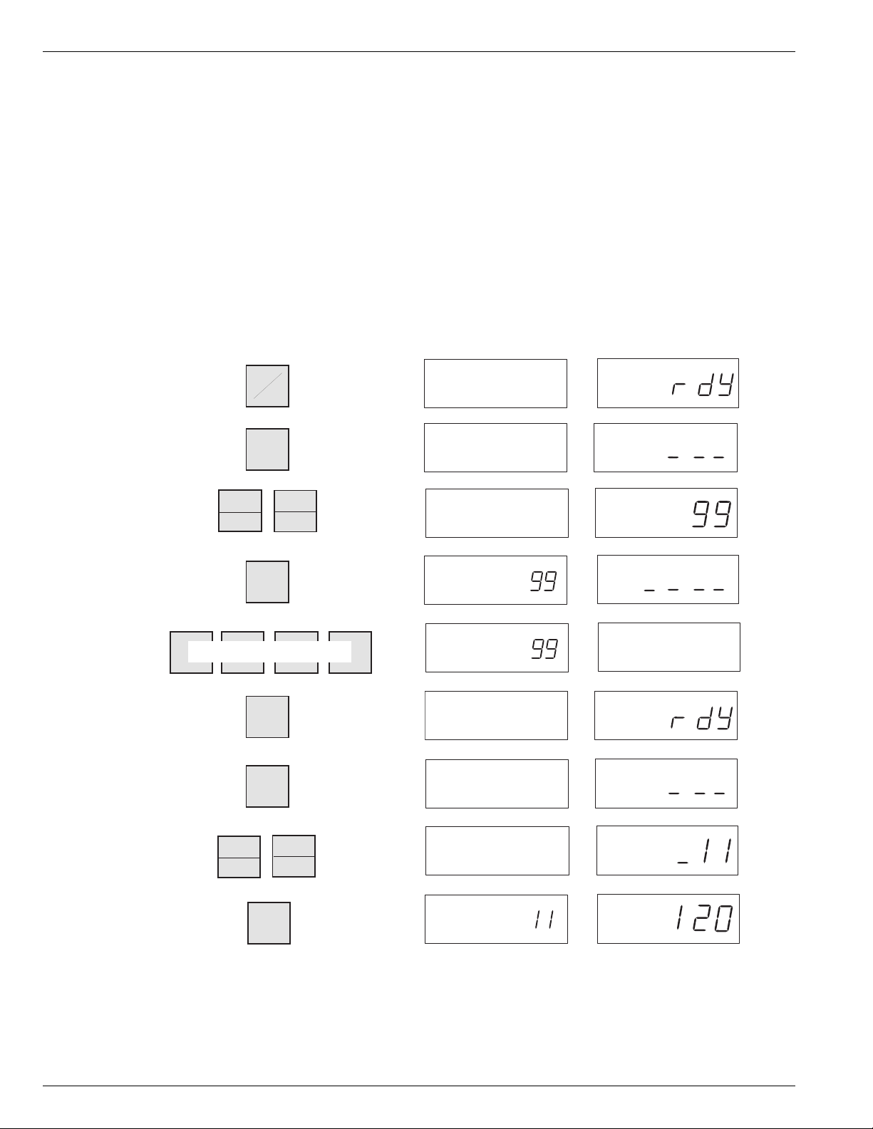
1. Connect the ac supply and the control battery. Four
dashes (----) will appear on the LCD display to indi-
cate that the clock needs to be set.
2. From the keyboard, press DISPLAY ON. The Ready
(rdY) prompt appears indicating the control is ready
for programming.
To set the year:
1. Press the CODE key and the numbers 1-5-3 (for
access code 153). Then press ENTER.
2. Press the CHANGE key. Enter the four digits of the
current year. Press ENTER.
To set the date:
1. Press the SCROLL key to advance the control to
Access Code 154. Code 154 can also be entered
manually.
2. Press CHANGE. Enter four digits for the month (01
to 12) and day (01 to 31). Single-digit months and
days are preceded by a zero. Press ENTER.
To set hour and minute:
1. Press SCROLL to advance the control to Access
Code 155. Code 155 can also be entered manually.
2. Press CHANGE and enter four digits for the hour (01
to 24) and minute (01 to 59). Press ENTER.
To set seconds:
1. Press SCROLL to advance the control to Access
Code 156. Code 156 can also be entered manually.
2. Press CHANGE and enter two digits for the seconds
(01 to 59) and press ENTER.
Use the SCROLL key to review the new calendar and
clock settings. Press ESCAPE to return to the Ready
(rdY) prompt.
6
Kyle Form 4C Microprocessor-Based Recloser Control Programming Guide
SETTING THE CONTROL CLOCK
(Access Codes 153–156)
USING THE KEYBOARD
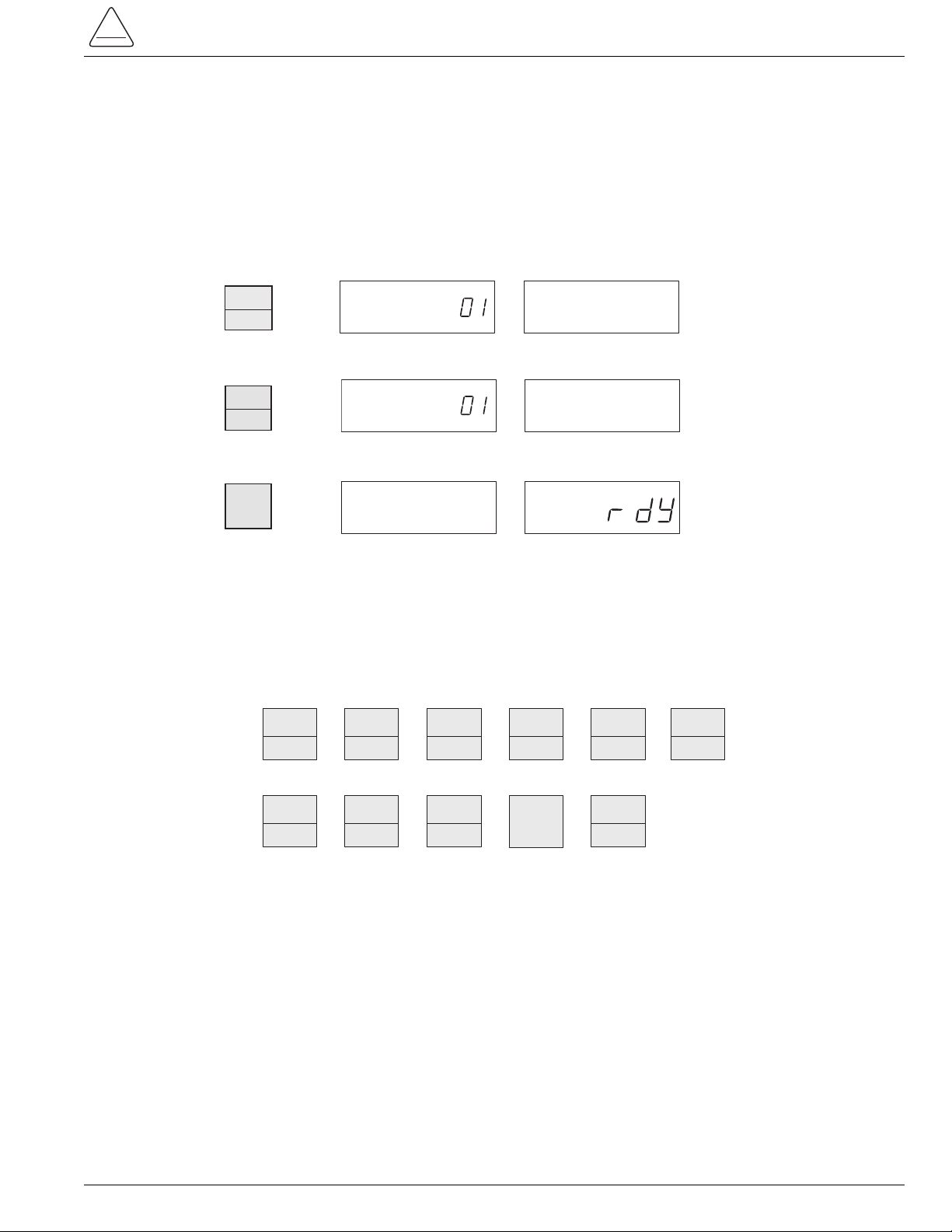
The following example of a Display Test illustrates the use of the keyboard for interrogation. The same basic step-by-
step descriptive procedure is used for all keyboard interrogation and program change operations.
Each step of the procedure is numbered, the appropriate key to be pressed is illustrated, and the resulting keyboard
display is shown.
DISPLAY
ON
OFF
DISPLAY
TEST
0
CLEAR ESCAPE
Step
No. Touch Key
1.
2.
3.
DISPLAY TEST
OR
CODE VALUE
EXAMINE PHASE
SCROLL CODE
CHANGE GROUND
Display
Message
Access
Code
Complex
TCC
Parameter
Value
CODE VALUE
CODE VALUE

Interrogation of Program Settings
The keyboard of the Form 4C control can be used to interrogate and display all programmed parameter settings. The
most commonly used parameters have dedicated function keys.
Use the following procedures for interrogation of control parameters. Be sure the display is ON and the rdY prompt is
displayed.
To interrogate other dedicated control parameters or status information, press any of the function keys, listed below, at
Step 1. Repeat Step 2 for any parameter with a phase and ground function. When pressed, the PHASE/GROUND key
will alternately display the phase and ground values of the appropriate parameters. (If the PHASE/GROUND key is
inadvertently pressed for a parameter without a phase and ground value, the control will ignore the command.)
Changing and Verifying Control Program Settings
Before making changes to control parameters, the operator must enter a security code that qualifies him to make
changes to control settings.
The security code must be re-entered if the display is turned off (or shuts off automatically after 10 minutes with no fur-
ther keyboard entry). This feature ensures that the Form 4C control returns to the read-only security access mode,
after the programming operator leaves the control.
The control can be programmed via the keyboard, independent of the position of the Supervisory ON/OFF switch.
The Supervisory ON/OFF switch must be ON when programming via the data port or through the digital communica-
tions accessory.
7
S280-77-4
!
SAFETY
FOR LIFE
MINIMUM
TRIP
1
PHASE
GROUND
Step
No. Touch Key
1.
2.
INTERROGATION OF MINIMUM TRIP
CODE VALUE
EXAMINE PHASE
SCROLL CODE
CHANGE GROUND
Display
Message
Access
Code
Complex
TCC
Parameter
Value
CODE VALUE
EXAMINE PHASE
displays the latest recorded value
of the appropriate parameter
displays the latest recorded value
of the appropriate parameter
ESCAPE
CODE VALUE
3.
OPER
1ST TCC
4
RECLOSE
1
7
TCC1
2
OPER
TO L.O.
5
RECLOSE
2
8
TCC2
3
RESET
TIME
6
RECLOSE
3
9
TARGETS
TARGET
COUNTERS
OPER.
COUNTER
SEQUENCE
POSITION
CURRENT
METERING

The following example illustrates how the control’s phase and ground minimum trip levels are changed and verified,
using the keyboard. Phase minimum trip is changed from 100 A to 200 A. Ground minimum trip is changed from 50 A to
100 A.
8
Kyle Form 4C Microprocessor-Based Recloser Control Programming Guide
DISPLAY
ON
OFF
ENTER
RECLOSE
3
Step
No. Touch Key
1.
6.
CODE
2.
3.
Change Phase Minimum Trip Value
CODE VALUE
EXAMINE PHASE
SCROLL CODE
CHANGE GROUND
Display
Message
Access
Code
Complex
TCC
Parameter
Value
CODE VALUE
CODE VALUE
CODE VALUE
ENTER
4.
EXAMINE PHASE
SCROLL CODE
CHANGE GROUND
CODE VALUE
9
RECLOSE
3
9
SCROLL CODE
MIN TRIP
7.
CODE VALUE
1
CHANGE
8.
EXAMINE PHASE
SCROLL CODE
CHANGE GROUND
CODE VALUE
5.
EXAMINE PHASE
SCROLL CODE
CHANGE GROUND
EXAMINE PHASE
SCROLL CODE
CHANGE GROUND
CODE VALUE
As the security code is
entered, the dashes disappear.
The security code will not appear
in the display.
ENTER SECURITY CODE
9.
CODE VALUE
ENTER NEW VALUE
EXAMINE PHASE
SCROLL CODE
CHANGE GROUND
10.
CODE VALUE
EXAMINE PHASE
SCROLL CODE
CHANGE GROUND
ENTER

To change the other control parameters, press any of the following keys after step 6. Repeat Steps 11 through 14 for
any parameter with a phase and ground function. When pressed, the PHASE/GROUND key will alternately display the
phase and ground values of the appropriate parameters. (If the PHASE/GROUND key is inadvertently pressed for a
parameter without a phase and ground value, the control will ignore the command.)
9
S280-77-4
!
SAFETY
FOR LIFE
Step
No. Touch Key
11.
12.
13.
EXAMINE PHASE
SCROLL CODE
CHANGE GROUND
EXAMINE PHASE
SCROLL CODE
CHANGE GROUND
EXAMINE PHASE
SCROLL CODE
CHANGE GROUND
Display
Message
Access
Code
Complex
TCC
Parameter
Value
CODE VALUE
CODE VALUE
CODE VALUE
ENTER
14.
EXAMINE PHASE
SCROLL CODE
CHANGE GROUND
CODE VALUE
CHANGE
PHASE
GROUND
ENTER NEW VALUE
TCC 1
2
RESET
TIME
6
TCC 2
3
RECLOSE
1
7
OPER
1ST. TCC
4
RECLOSE
2
8
OPER.
TO L.O.
5
RECLOSE
3
9

Changing Control Settings Using Access Codes
Use the following procedure to interrogate or change any control settings of parameters without dedicated keys. Refer
to Table 1 or to the control information label located inside the cabinet door to locate the desired parameter and appro-
priate access code. Enter the desired access code at Step 8.
Change Alternate Phase Minimum Trip Value
(Steps 2 through 6 are required to enter security code. If already in security, omit steps 2 through 6.)
Alternate phase minimum trip is changed from 120 A to 240 A.
Alternate ground minimum trip is changed from 60 A to 120 A.
10
Kyle Form 4C Microprocessor-Based Recloser Control Programming Guide
ENTER
RECLOSE
3
Step
No. Touch Key
1.
6.
CODE
2.
3.
CODE VALUE
EXAMINE PHASE
SCROLL CODE
CHANGE GROUND
Display
Message
Access
Code
Complex
TCC
Parameter
Value
CODE VALUE
CODE VALUE
VALUE
ENTER
4.
EXAMINE PHASE
SCROLL CODE
CHANGE GROUND
CODE VALUE
9
RECLOSE
3
9SCROLL CODE
7.
CODE VALUE
DISPLAY
ON
EXAMINE PHASE
SCROLL CODE
CHANGE GROUND
CODE
8.
EXAMINE PHASE
SCROLL CODE
CHANGE GROUND
CODE VALUE
5.
EXAMINE PHASE
SCROLL CODE
CHANGE GROUND
EXAMINE PHASE
SCROLL CODE
CHANGE GROUND
CODE VALUE
As the security code is
entered, the dashes disappear.
The security code will not appear
in the display.
ENTER SECURITY CODE
9.
CODE VALUE
EXAMINE PHASE
SCROLL CODE
CHANGE GROUND
ENTER
CODE
MINIMUM
TRIP
1
MINIMUM
TRIP
1
OFF

Control Interrogation Using The
SCROLL Key
The scroll key provides parameters and status of the fol-
lowing access codes in numerical sequence, offering the
convenience of obtaining basic parameter and control
status information without selecting individual access
codes. The code groups are:
•Basic programming settings (Codes 01 through 09)
•Alternate minimum trip (Code 11)
•Supervisory close reset time (Code 12)
•Features ON/OFF (Codes 20 through 26)
In the Access Code Description section of this manual, a
YES in the Scroll column indicates that the SCROLL key
can be used for interrogation; a NO indicates that the
scroll function is not accessible.
Control Interrogation Using The
SELECT ACCESSORY Key
The SELECT ACCESSORY key provides ON/OFF sta-
tus information of enhanced features:
•Complex TCC Setup (Codes 100 and 110)
•Sensitive Ground/Earth Fault (Code 120)
•High-Current Trip (Code 130)
•High-Current Lockout (Code 140)
This allows the operator a quick overview of modifica-
tions to the control parameters without individual code
selection.
Control Interrogation Using The
Accessory SCROLL Key
Some features on the Form 4C control contain multiple
settings. These features are:
•Complex TCC1 Code 100 through 104
•Complex TCC2 Setup Code 110 through 114
•Sensitive Ground/Earth Fault Code 120 through 124
•High-Current Trip Code 130 through 134
•High-Current Lockout Code 140 through 143
The ACCESSORY SCROLL key provides the specific
parameters of the features obtained with the SELECT
ACCESSORY key.
11
S280-77-4
!
SAFETY
FOR LIFE
Step
No. Touch Key
10.
15.
11.
12.
CODE VALUE
Display
Message
Access
Code
Complex
TCC
Parameter
Value
CODE VALUE
CODE VALUE
ENTER
13.
EXAMINE PHASE
SCROLL CODE
CHANGE GROUND
CODE
VALUE
16.
CODE VALUE
CHANGE
EXAMINE PHASE
SCROLL CODE
CHANGE GROUND
CODE VALUE
14.
EXAMINE
CHANGE GROUND
ENTER
EXAMINE PHASE
SCROLL CODE
CHANGE GROUND
CHANGE GROUND
PHASE
GROUND
VALUE
CODE
CHANGE
ENTER NEW VALUE
ENTER NEW VALUE
EXAMINE PHASE
CHANGE GROUND

DOWNLOADING TO A DATA
READER
The Data Reader (Figure 3) can be used with the Cooper
Power Systems Form 4C recloser control and CL-4, CL-4B,
CL-4C, and CL-5A regulator controls. Data gathered
from recloser and regulator controls is stored in the Data
Reader for later downloading into a personal computer
for system analysis. A single Data Reader can collect
and store data from 20 Form 4C controls, 100 regulator
controls, or any equivalent combination of readings from
the two types of controls. The Form 4C control is com-
patible with Data Reader Software DOS Version 4.0 or
above and with Windlows-based software, CCI version
1.02 and CCI version 3.01.
To operate the Data Reader:
1. Connect the Data Reader to the data port (Figure 2).
2. Press and hold the START DATA READING button.
All three LED lights will illuminate.
3. When the READING and READING COMPLETE
lights go out, release the START DATA READING
button. The BATTERY OK light will remain illuminated.
The READING light will illuminate and remain on
while the data reader obtains data from the control.
When the data has been recorded, the READING
COMPLETE light will illuminate.
4. Disconnect the Data Reader from the data port.
For additional information on the operation of the Data
Reader, refer to Service Information S225-30-1 Data
Reader Operating and Maintenance Instructions.
12
Kyle Form 4C Microprocessor-Based Recloser Control Programming Guide
Figure 3.
Data Reader plugs into data port on the Form 4C
Control Panel.
901016KMA -F

CONTROL INTERFACE
SOFTWARE PROGRAM
An optional Form 4C INTERFACE™software program
is available to enable the control to be programmed and
operated with a personal computer. It is used to send
and receive data from the control and to provide access
to the Data Reader’s data files.
Form 4C INTERFACE software permits complete
uploading and downloading of all data stored in the con-
trol. It includes a database manager that allows the
operator to import, export, or delete data, such as con-
trol settings and data records from the database.
The software enables the user to print various reports
and provides organized menus of data including:
•all control programming parameters
•event recorder information
•load profile records
•demand metering records
•duty cycle monitor data
The software also allows the user to operate the control
directly. Form 4C controls with the Sensitive
Ground/Earth Fault feature must use KSPS2 software
DOS version 2.0 or later.
The Form 4C INTERFACE program (catalog number
KCCI-30-F4) can be used on any personal computer
with a minimum of Microsoft®Windows 95®operating
system, 16 MB of RAM, and a 266 MHz Intel®Pentium®
processor.
CONTROL OPERATION WITH
A PERSONAL COMPUTER
A Data Port-to-Computer Interface Cable is available to
permit connection of a personal computer to the data
port on the front panel of the Form 4C control. The inter-
face cable consists of an EIA232-connector on one end
and a data port 9-pin connector on the other end.
The cable includes an adapter that converts low-power
Form 4C control data-port signals to an EIA232 inter-
face. This will connect directly to personal computers
with a 25-pin serial port and allows downloading of data
from the control into the computer (Figure 4).
The personal computer can also be used to upload all
control parameter settings into the control for convenient
programming. The complete set of control operating
parameters can be programmed and verified locally at
the installation site or at a remote site. Programming
data for each control is stored in the computer and can
be printed out and archived for future reference. A print-
out of each control’s program settings can also be kept
at the installation site for reference during future inspec-
tions.
13
S280-77-4
!
SAFETY
FOR LIFE
Figure 4.
The Form 4C Control can be programmed directly
from a personal computer (screen shown with
KSPS2 software).
901024KMA -F

Table 1 is a list of the standard access codes provided
on all Form 4C controls. A detailed list of program set-
tings, parameter descriptions, and keyboard access
codes appears in the Access Code Description section
of this manual. Access codes and parameter descrip-
tions can also be found on the control information label
located inside the cabinet door.
*Note: Programming of these access codes is required for
basic control operation.
14
Kyle Form 4C Microprocessor-Based Recloser Control Programming Guide
PROGRAMMING
*01 Minimum Trip - Phase and Ground
* 02 TCC1 - Phase and Ground
* 03 TCC2 - Phase and Ground
* 04 TCC1 Operations - Phase and Ground
* 05 Operations to Lockout - Phase and Ground
* 06 Reset Time
* 07 Reclose #1
* 08 Reclose #2
* 09 Reclose #3
* 10 CT Selection
* 11 Alternate Minimum Trip - Phase and Ground
12 Supervisory Close Reset Time
PHASE IDENTIFICATION
17 Bushings 1-2 Phase Identifier
18 Bushings 3-4 Phase Identifier
19 Bushings 5-6 Phase Identifier
FEATURE ON/OFF
20 Sequence Coordination
21 Target Reset After Successful Reclose
22 Operations Counter
23 Event Recorder
*24 Recloser Duty Monitor
25 Ground Trip Precedence
26 Supervisory Via Momentary Contact
TARGETS
30 Target Status/Reset
32 Target Counter - Ground
33 Target Counter - Phase 1-2
34 Target Counter - Phase 3-4
35 Target Counter - Phase 5-6
36 Target Counter - Sensitive Ground Fault
SEQUENCE POSITION
38 Sequence Position
OPERATIONS COUNTER
39 Operations Counter
METERING
40 Instantaneous Current - Ground
41 Instantaneous Current - Phase 1-2
42 Instantaneous Current - Phase 3-4
43 Instantaneous Current - Phase 5-6
44 Demand Current- Ground
45 Demand Current- Phase 1-2
46 Demand Current- Phase 3-4
47 Demand Current- Phase 5-6
48 Maximum Demand Current - Ground
49 Maximum Demand Current - Phase 1-2
50 Maximum Demand Current- Phase 3-4
51 Maximum Demand Current - Phase 5-6
57 Select Integration Intervals - Phase and
Ground
STATUS CODES
65 Accessory Status Code
67 Alternate Minimum Trip Status
MALFUNCTION CODES
66 Malfunction Status Code
TCC GROUP
* 70 TCC Group
LINE FREQUENCY
* 71 Line Frequency
FIRMWARE VERSION/CONTROL ID
72 CPU Firmware Version
76 Control Identification Number
77 CPU Firmware Revision Number
78 Display Board Firmware Version Number
CLOSE/RETRY
74 Close Retry Time
79 Number of Close Retry Attempts
ACCESS ACCESS
CODE PARAMETER CODE PARAMETER
TABLE 1
Form 4C Control Standard Access Codes
STANDARD ACCESS CODES AND PARAMETERS

15
S280-77-4
!
SAFETY
FOR LIFE
DIGITAL COMMUNICATIONS
80 Data Port Baud Rate Code
81 Real-Time Digital Communications Port Baud
Rate Code
82 Control Communications Address
83 Real-Time Digital Communications Port Hand-
shake Mode Code
84 Number of Line-Sync Characters
85 Real-Time Communications Port Transmit
Enable Delay
86 Auto Time-Tagged Reset
SECURITY CODES
90 Security Code for Level 1
91 Security Code for Level 2
92 Security Code for Level 3
99 Enter System Security
TIME–CURRENT CURVE MODIFIERS
100 Complex TCC1 (ON/OFF) - Phase and
Ground
101 TCC1 Selection - Phase and Ground
102 TCC1 Constant Time Adder - Phase and
Ground
103 TCC1 Multiplier Value - Phase and Ground
104 TCC1 Minimum Response Time - Phase
and Ground
110 Complex TCC2 (ON/OFF) - Phase and
Ground
111 TCC2 Selection - Phase and Ground
112 TCC2 Constant Time Adder - Phase and
Ground
113 TCC2 Multiplier Value - Phase and Ground
114 TCC2 Minimum Response Time - Phase
and Ground
SENSITIVE GROUND/EARTH FAULT
120 Sensitive Ground/Earth Fault (ON/OFF)
121 Percent of Ground Minimum Trip
122 Percent of Alternate Ground Minimum Trip
123 Sensitive Ground/Earth Trip Time
124 Operations to Lockout
125 Sensitive Ground/Earth Fault Status
HIGH-CURRENT TRIP
130 High-Current Trip - Phase (ON/OFF)
131 High-Current Trip - Ground (ON/OFF)
132 High-Current Trip (Multiple of Minimum Trip)-
Phase and Ground
133 High-Current Trip (Trip Time Delay) - Phase
and Ground
134 High-Current Trip (Active Shot Number)- Phase
and Ground
HIGH-CURRENT LOCKOUT
140 High-Current Lockout - Phase (ON/OFF)
141 High-Current Lockout - Ground (ON/OFF)
142 High-Current Lockout (Multiple of Minimum
Trip) - Phase and Ground
143 High-Current Lockout (Active Shot Number)-
Phase and Ground
CLOCK
* 153 Time Clock - Year
* 154 Time Clock - Month and Day
* 155 Time Clock - Hour and Minute
* 156 Time Clock - Second
EVENT RECORDER
160 Number of Events Since Last Reset
161 Event Number
162 Event Type
163 Month and Day
164 Hour and Minute
165 Second
166 Ground Current
167 Phase 1-2 Current
168 Phase 3-4 Current
169 Phase 5-6 Current
DUTY CYCLE MONITOR
* 170 100% Duty Factor
171 Phase 1-2 Duty Cycle
172 Phase 3-4 Duty Cycle
173 Phase 5-6 Duty Cycle
LOAD PROFILE MONITOR
180 Reading Number
181 Time - Hour and Minute
182 Ground Current
183 Phase 1-2 Current
184 Phase 3-4 Current
185 Phase 5-6 Current
SWITCH MODE
190 Active TCC Selection
191 Minimum Target Sensing, Phase and Ground
192 Alternate Minumum Trip Target Sensing,
Phase and Ground
ACCESS ACCESS
CODE PARAMETER CODE PARAMETER
TABLE 1 (cont’d)
Form 4C Control Standard Access Codes

16
Kyle Form 4C Microprocessor-Based Recloser Control Programming Guide
Table 3 is a list of the access codes for the firmware
accessories available for the Form 4C control. A detailed
list of program settings, parameter descriptions, and
keyboard access codes appears in the Access Code
Description section of this manual. Access codes and
parameter descriptions can also be found on the control
information label located inside the cabinet door.
The Form 4C control has numerous firmware acces-
sories available to provide the user with new alterna-
tives for improving the performance of the distribution
system.
The firmware accessories include not only new function-
al firmware, but also additional hardware and operation
with KSPS2 Interface software Version 4.0. Each
firmware accessory includes local operation via a toggle
switch, LED indication of the status, and an LED test
pushbutton. Access codes interrogated via the front
panel keypad are also available for status.
The firmware accessories include the Optional Universal
I/O board as part of the design for access to the CPU,
control points, and status points. Each status point is
available via a single-pole, double-throw contact.
Serial communications are also included for all the avail-
able firmware accessories and documented in Refer-
ence Information R280-90-11 Communications Point
Data Base for Digital Communications Protocol Data
2179.
The CPU firmware (Access Code 72) varies based upon
the functionality required. Table 2 lists the values for
Protocol 2179.
STATUS CODES
63 Hot Line Tag (HLT) Status
64 Switch Mode Status
68 Trip on TCC2 Status
125 Sensitive Ground/Earth Fault Status
SWITCH MODE
190 TCC Selection
191 Minimum Target Sensing
192 Alternate Minimum Target Sensing
ACCESS ACCESS
CODE PARAMETER CODE PARAMETER
TABLE 3
Form 4C Control Accessory Access Codes
ACCESSORY ACCESS CODES AND PARAMETERS
Firmware Accessory CPU Firmware (Access Code 72) Protocol 2179
8.15 9.15 10.15 11.15 12.15 13.15
Hot Line Tag ✓✓✓
Trip On TCC2 ✓✓ ✓
Sensitive Ground/Earth Fault ON/OFF ✓✓✓
Switch Mode ✓✓✓
TABLE 2
CPU Firmware Accessories

17
S280-77-4
!
SAFETY
FOR LIFE
Access codes, parameter descriptions, and security lev-
els used in programming the Form 4C control are listed
in this section of the programming guide. The high and
low limits and increments of the code parameter values
are also specified.
The control is furnished with indicated factory settings.
These settings are not recommended for customer use.
The control must be programmed with applicable set-
tings prior to installation.
ACCESS CODE DESCRIPTIONS
Programming
Security Limits
Access Factory
Code Write Read Scroll High Low Incr Parameter Settings
01 1 0 YES 1600 50 1 Minimum Trip - Phase 100
01 1 0 YES 800 5 1 Minimum Trip - Ground 50
•Minimum trip is a threshold value at which a system
overcurrent is detected.
•Minimum Trip is set for both phase and ground
through a range of settings based on the recloser’s
CT ratio.
CT ratio 500:1 allows a range from 25 to 800 A
phase and 2 to 400 A ground.
CT ratio 1000:1 allows a range from 50 to 1600 A
phase and 5 to 800 A ground.
CT ratio 2000:1 allows a range from 100 to 2400 A
phase and 10 to 1600 A ground.
•All values are adjusted in increments of 1.
•The control accepts only the values within the limits
preset in the control. Attempts to enter other values
results in a LO/HI message.
•Use the PHASE/GROUND key to select phase and
ground.
Security Limits
Access Factory
Code Write Read Scroll High Low Incr Parameter Settings
02 1 0 YES -- -- -- TCC1 - Phase 104
02 1 0 YES -- -- -- TCC1 - Ground 106
•TCC is an abbreviation for time–current curve. A
TCC is used as a protective response to initiate a
trip signal when the minimum trip value (phase or
ground) is exceeded.
•Identifies the programmed TCC1 - phase and ground
curves selected from the TCC timing groups of the
Form 4C control. (Reference Access Code 70). In
most situations, TCC1 is designated as the fast
curve.
•Time–current characteristics for TCC1 - phase are
independent of time–current characteristics for TCC1
ground.
•Time–current characteristics of TCC1 - phase and
ground are independent of time–current characteris-
tics of TCC2 - phase and ground.
•When TCC characteristics are modified, the control
readout indicates a modified curve by prefixing the
TCC number with a lower-case c(Access Codes
100-114).

18
Kyle Form 4C Microprocessor-Based Recloser Control Programming Guide
Programming (cont’d)
Security Limits
Access Factory
Code Write Read Scroll High Low Incr Parameter Settings
03 1 0 YES -- -- -- TCC2 - Phase 117
03 1 0 YES -- -- -- TCC2 - Ground 135
•TCC is an abbreviation for time–current curve. A
TCC is used as a protective response to initiate a
trip signal when the minimum trip value (phase or
ground) is exceeded.
•Identifies the programmed TCC2 - phase and ground
curves selected from the TCC timing groups of the
Form 4C control. (Reference Access Code 70). In
most situations, TCC2 is designated as the slow or
delayed curve.
•Time–current characteristics for TCC2 - phase are
independent of time–current characteristics for TCC2
ground.
•Time–current characteristics of TCC2 - phase and
ground are independent of time–current characteris-
tics of TCC1 - phase and ground.
•When TCC characteristics are modified, the control
readout indicates a modified curve by prefixing the
TCC number with a lower-case c(Access Codes
100-114).
Security Limits
Access Factory
Code Write Read Scroll High Low Incr Parameter Settings
04 1 0 YES 4 0 1 Operations on TCC1 - Phase 2
04 1 0 YES 4 0 1 Operations on TCC1 - Ground 2
•Selection of zero to four trip operations on TCC1. •Time–current characteristics for phase are indepen-
dent of TCC characteristics for ground. The number
of phase and ground TCC1 operations do not have
to match.
Security Limits
Access Factory
Code Write Read Scroll High Low Incr Parameter Settings
05 1 0 YES 4 1 1 Operations to Lockout - Phase 4
05 1 0 YES 4 1 1 Operations to Lockout - Ground 4
•Lockout is a control state with no further automatic
recloses.
•Selection of one to four trip operations before the
control locks out.
•The number of operations to lockout for phase and
ground do not have to match.
•Use PHASE/GROUND key to select phase or
ground.

19
S280-77-4
!
SAFETY
FOR LIFE
Security Limits
Access Factory
Code Write Read Scroll High Low Incr Parameter Settings
09 1 0 YES 45.0 1.8 0.1 Reclose #3 (seconds) 5
•Reclose #3 is the open time duration after the
third trip operation prior to automatic reclosing.
•Selects the reclose interval after the third trip
operation.
Security Limits
Access Factory
Code Write Read Scroll High Low Incr Parameter Settings
08 1 0 YES 45.0 1.8 0.1 Reclose #2 (seconds) 2
•Reclose #2 is the open time duration after the
second trip operation prior to automatic reclosing.
•Selects the reclose interval after the second trip
operation.
Security Limits
Access Factory
Code Write Read Scroll High Low Incr Parameter Settings
07 1 0 YES 45.0 0.3 0.1 Reclose #1 (seconds) 2
•Reclose #1 is the open time duration after the
first trip operation prior to automatic reclosing.
•Selects the reclose interval after the first trip
operation.
Programming (cont’d)
Security Limits
Access Factory
Code Write Read Scroll High Low Incr Parameter Settings
06 1 0 YES 180 3 1 Reset Time (seconds) 30
•Reset timing begins after a successful reclose
operation.
•Successful reclose is determined when the
recloser is closed and the current sensed is
below the minimum trip values (phase and
ground).
Reclose
#1
Reclose
#2
Reclose
#3
C
LOSED
OPEN
Figure 5.
Typical four trips to lockout operation. Fault current ini-
tiated with recloser closed.

20
Kyle Form 4C Microprocessor-Based Recloser Control Programming Guide
Security Limits
Access Factory
Code Write Read Scroll High Low Incr Parameter Settings
11 1 0 YES 1600 50 1 Alternate Minimum Trip (Amps) - Phase 120
11 1 0 YES 800 5 1 Alternate Minimum Trip (Amps) - Ground 60
•Sets an alternate minimum trip value for both phase
and ground through a range of settings based on
programmed CT selection (Access Code 10).
CT ratio 500:1 allows a range from 25 to 800 A
phase and 2 to 400 A ground.
CT ratio 1000:1 allows a range from 50 to 1600 A
phase and 5 to 800 A ground.
CT ratio 2000:1 allows a range from 100 to 2400 A
phase and 10 to 1600 A ground.
•Alternate Minimum Trip is turned on and off via the
ALTERNATE MINIMUM TRIP switch on the front
panel.
•Alternate Minimum Trip is available using the
ALTERNATE MINIMUM TRIP front panel switch or
through supervisory control.
•Setting the alternate minimum trip values equal to the
values in Access Code 01, disables Access Code 11.
Programming (cont’d)
Security Limits
Access Factory
Code Write Read Scroll High Low Incr Parameter Settings
10 1 0 NO 2000 500 -- CT Selection 1000
•Programs the control to operate with a recloser cur-
rent transformer ratio of 500:1, 1000:1, or 2000:1.
•Select 500 / 1000 / 2000 using the CHANGE key.
•Verify recloser current transformer ratio matches pro-
grammed setting.
Security Limits
Access Factory
Code Write Read Scroll High Low Incr Parameter Settings
12 1 0 YES 60 0 1 Supervisory Close Reset Time (seconds) 30
•Programs the time interval during which the control
is set for one trip to lockout on TCC2. This occurs
following a supervisory close signal (discrete
SCADA or digital communications).
•If programmed for zero seconds, the control per-
forms the normal programmed sequence.
•At the end of this time interval, the control returns to
its normal programmed sequence.
Other manuals for Kyle Form 4C
1
Table of contents
Popular Industrial Equipment manuals by other brands

Aventics
Aventics MSC Series Assembly instructions

NORTHERN ELECTRIC
NORTHERN ELECTRIC RVG-1 Installation and operation manual

Garnet
Garnet SeeLevel ProSeries II 810-PS2 manual

SMC Networks
SMC Networks CXS Series manual

Altana
Altana BYK wave-scan 3 ROBOTIC operating instructions

A.E.B.
A.E.B. AEB388 Assembly & instruction manual