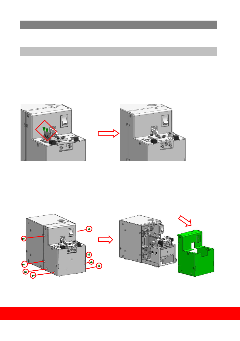
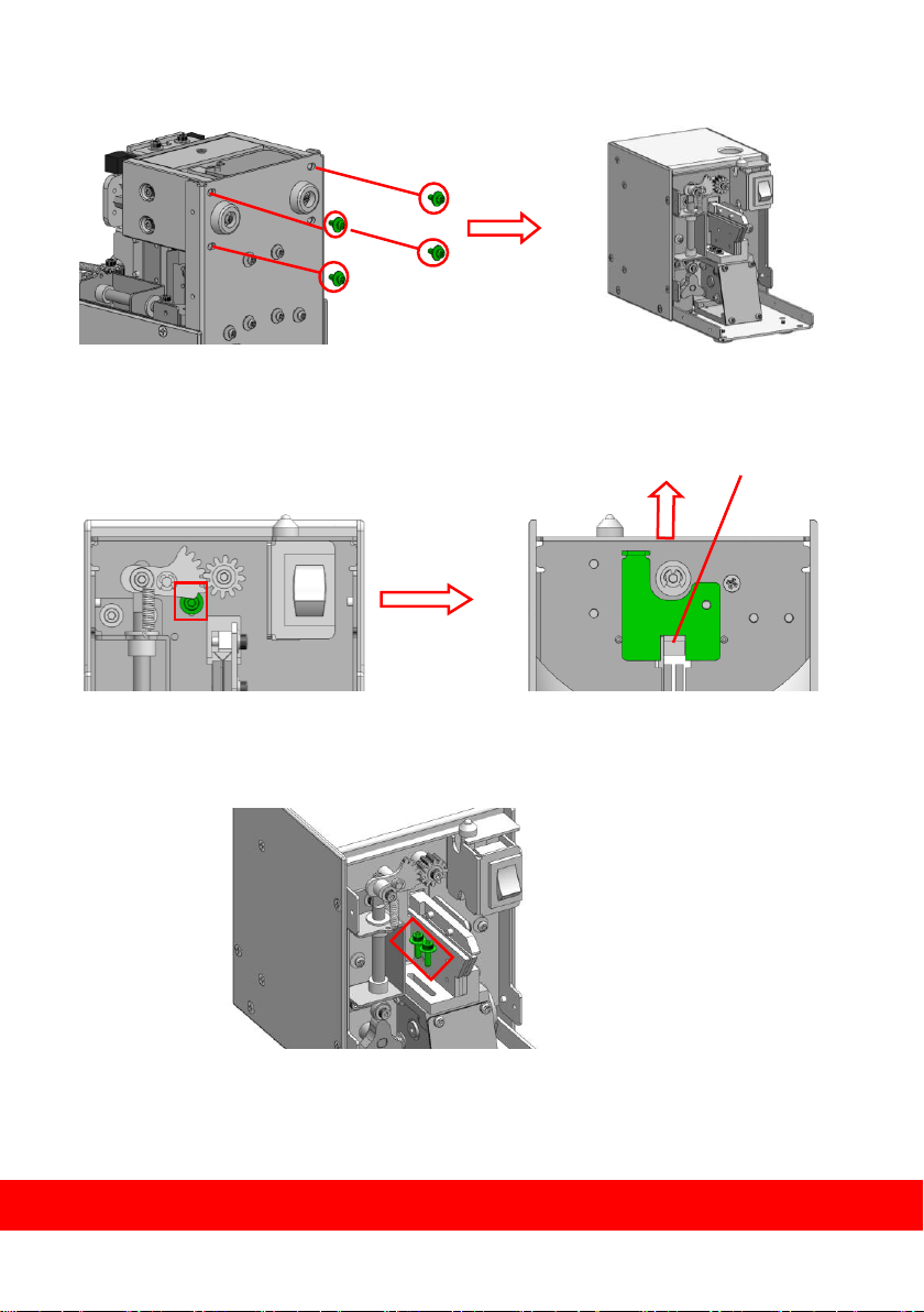
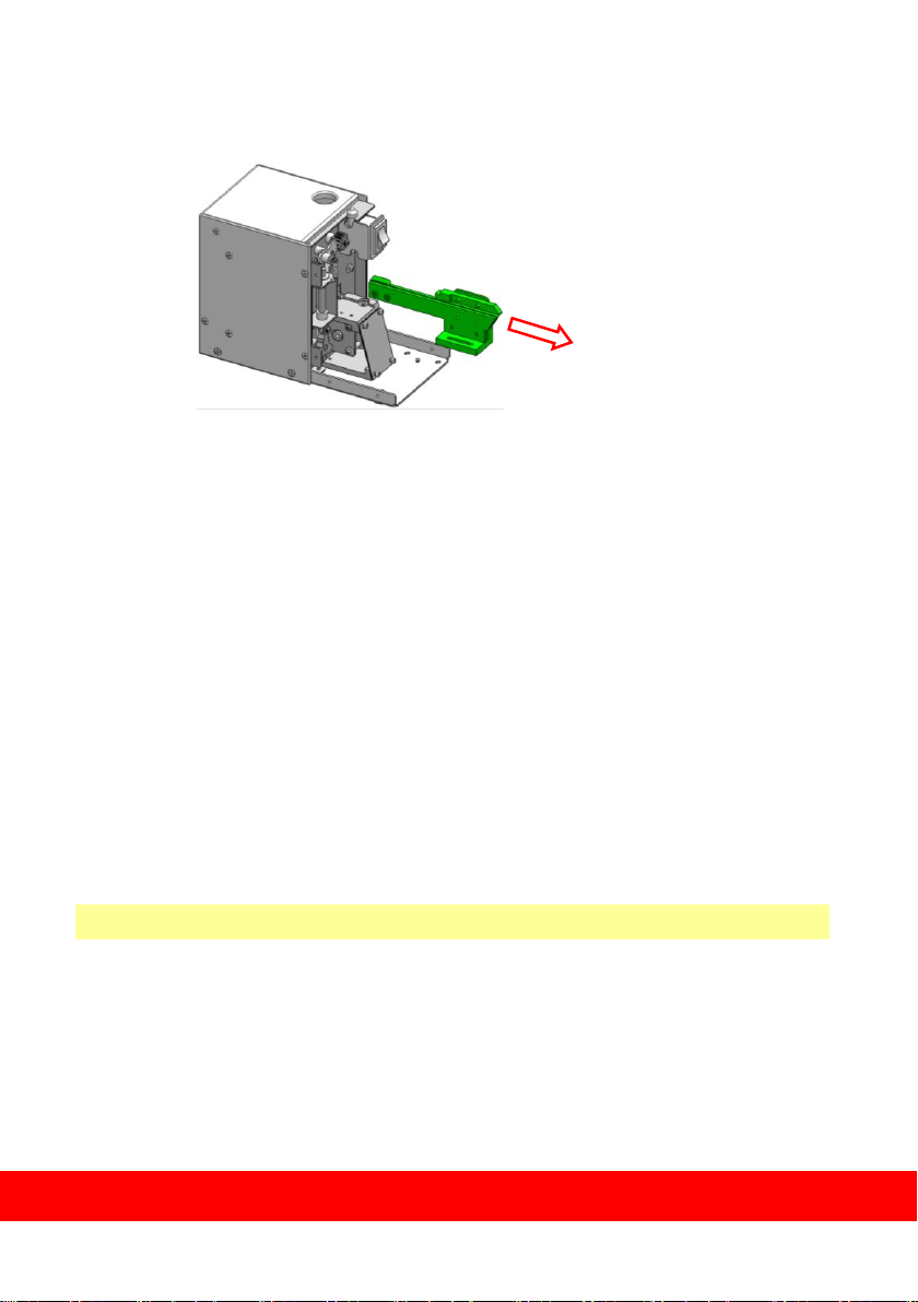
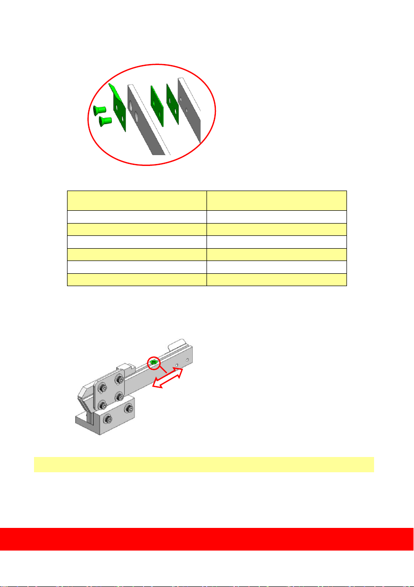
Kilews KFA-0820A User manual

AUTOMATIC SCREW FEEDER
KFA-0820A ((VACUUM TYPE)
INSTRUCTION MANUAL
(ENGLISH)
Please read this manual thoroughly, before operating the unit and retain it
for future reference.
Patented in China, Taiwan, Japan & Korea.
Imitation of product will be caused prosecution.
Y2F147-1-001

SAFETY INSTRUCTIONS
PLEASE NOTE FOLLOWING CONDITIONS BEFORE USING KILEWS KFA-0820
◎For a normal performance, please install this machine on a flat and stable
working table, do not slant or pad, otherwise machine function might be
affected.
◎Turn off the power switch and unplug the AC adaptor when this machine
is not being used for a period of time.
◎To avoid damage and malfunction, use the AC adaptor supplied with this
machine only.
◎Keep the surface of the rail groove clean and free from dust and oil.
Failure to keep the rail groove clean could result in damage to the
machine.
◎The applied screws must be clean without grease or dust, and screw size
is within specified range as machine rail.
◎Handle screws on rails with care, do not use excess force to remove them
or the rails may be damaged.
◎When scooping chamber is turning, do not put fingers or objects other
than screws into the chamber.
◎Do not turn ON the power switch before the rails are set properly for
operation.
◎In case of malfunction during operation, please turn off the power and
unplug the AC adaptor. Contact your supplier at once.
Whenever this machine requires service, please contact your supplier for
assistance, or go to our website & e-mail us your contact detail and
requirement, we will respond ASAP.

CONTENTS
CHECK BEFORE OPERATION.......................................................1
CHECK THE SCREW SIZE .............................................................................. 1
FUNCTIONS WITH ADJUSTING HOLES ON HOUSING AND PCB ..1
ADJUSTMENT ..............................................................................2
ADJUST THE RAIL ASSEMBLY .........................................................................2
DISMANTLE THE RAIL ASSEMBLY .............................................................2
ADJUST THE WIDTH OF RAIL ASSMEBLY ..................................................5
INSERT THE RAIL ASSEMBLY ...................................................................7
ADJUST THE HOLDING PLATE.........................................................................9
ADJUST THE FEEDING STRUCTURE ............................................................. 10
ADJSUT THE SENSOR FUNCTION .................................................................. 11
ADJUST THE BRUSH .................................................................................... 12
OPERATION METHOD ................................................................13
LOAD SCREWS INTO CHAMBER .................................................................... 13
DISPLAY PANEL OPERATION.........................................................................14
MAINTENANCE & TROUBLE SHOOTING .....................................17
MAINTENANCE & CLEANING .....................................................18
INTERNATIONAL WARRANTY CONDITIONS.............................. 19

1
CHECK BEFORE OPERATING
CHECK THE SCREW SIZE
Measure the size precisely on each part of applied screw with a caliper.
Table a.
FUNCTIONS WITH ADJUSTING HOLES ON HOUSING AND PCB
A. POWER
POWER SWITCH
B. INDICATION
LED INDICATION LIGHT
C. DC POWER
DC POWER HOLE
D. SIGNAL
GROUNDING & SIGNAL HOLE
a
Dia. of Screw Head
b
Height of Screw Head
c
Screw Length
d
Dia. of Screw Bolt.
e
Screw Total Length
A.
B.
C.
D.

2
ADJUSTMENT
After checking the screw size, it needs to adjust all related parts according to the screw
size for the first use.
ADJUST THE RAIL ASSEMBLY
DISMANTLE THE RAIL ASSEMBLY
1. Remove the fixing screws of guide assembly, dismantle the guide assembly.
2. Remove the fixing screws (8pcs) of front housing, and take off the front housing.

3
3. Dismantle the fixing screws*4 of feeding structure, and take it off.
4. Facing the machine, loosen the screw of lock gate, open the lock gate upward and
fasten screw.
5. Remove the fixing screws of rail assembly
Open the lock gate wide

4
6. Draw out the rail assembly from the machine.
※NOTE THE FOLLOWING WHEN MAKING ABOVE ADJUSTMENT ※
a. Before dismantle the rail assembly, please confirm the lock gate status is open.
b. Dismantle the guide assembly first, and then take off the front housing.
c. Loosen the fixing screw of lock gate only, do not remove the screw.

5
ADJUST THE WIDTH OF RAIL ASSEMBLY
1. Remove the fixing screw on the rear end of rail assembly.
2. Remove the fixing screw on the front end of side of rail assembly, take off the
tooling plate.
3. According to Table b, insert the suitable tooling plate into the rail groove for the
width required and tighten the screw of step 2.

6
4. Insert the tooling plate in the rear end of rail according to Table b, fasten the screw
of step 1.
※COMBINATION OF THE THICKNESS FOR REFERENCE ※Table b
Dia. of Screw Bolt (d) mm
Accessory-Tooling Plate (Rear) mm
0.8
1.0mm
1.0
1.2mm
1.2
1.4mm
1.4
1.6mm
1.6
1.8mm
2.0
2.2mm
5. After width adjustment of the rail assembly, place a screw into the groove and slide
it up and down to both sides, to check whether the movement is smoothly.
※NOTE THE FOLLOWING WHEN MAKING ABOVE ADJUSTMENT ※
a. Please must keep the width of rail from the beginning to the end uniformly.
b. When adjusting the width of front rail assembly, the screw of step 2 must be
fastened.

7
INSERT THE RAIL ASSEMBLY
1. After the width adjustment of rail assembly, insert it into machine, and then fasten
screw.
2. Install the feeding structure, and then fasten screw.
3. Loosen the fixing screw of rail assembly, keep 0.2~0.5mm open space between the
front end of rail assembly to circled plate, and then fasten screw.
0.2~0.5mm

8
4. Set the lock gate, keep 0.2~0.5mm open space between gate to rail assembly.
※NOTE THE FOLLOWING WHEN MAKING ABOVE ADJUSTMENT ※
a. When inserting the rail assembly, it must to keep 0.2~0.5mm open space from the
circled plate.
b. Keep 0.2~0.5mm open space between the lock gate to rail assembly.
c. Make sure the front and rear of feeding structure to avoid installing it reversely.
0.2~0.5m
m

9
ADJUST THE HOLDING PLATE
1. Loosen the screw of fixing holding plate.
2. Adjust the height of holding plate by tooling plate, and fasten the screw of step 1.
3. Place some screws into the groove and slide them up and down, to check whether
the movement is smoothly.
※NOTE THE FOLLOWING WHEN MAKING ABOVE ADJUSTMENT ※
a. When adjusting the holding plate, the screw of step 1 must be tightened.

10
ADJUST THE FEEDING STRUCTURE
1. Loosen the fixing screw of feeding structure
2. Adjust the groove of circled plate to the middle of rail, and then fasten the screws of
step 1.
※NOTE THE FOLLOWING WHEN MAKING ABOVE ADJUSTMENT ※
a. After adjustment, operate the machine to make sure the groove of circled plate to
the middle of rail when running.
b. The screw of feeding structure must fasten completely to avoid the screws falling
into machine.

11
ADJUST SENSOR FUNCTION
1. Loosen the fixing screw of sensor fixing plate
.......
2. Make sure to cover half of the hole, and then fasten the screw of step 1.
※NOTE THE FOLLOWING WHEN MAKING ABOVE ADJUSTMENT ※
a. Make sure to cove half of the hole, and do adjustment to ensure the sensor function
no problem.

12
ADJUST THE BRUSH
1. Swing the brush to stay almost horizontal, loosen screw on the side of brush bracket.
2. Place 5~8 screws into the rail groove close to the holding plate rear end, loosen 2
screws on the side of the brush bracket, swing the brush down and adjust the height,
the brush just touch the screw heads slightly, and tighten the screws after adjustment.
3. When fix the brush position, keep suitable space for the Front Plate and Fixing Plate.
※NOTE THE FOLLOWING WHEN MAKING ABOVE ADJUSTMENT ※
a. After adjustment of the height of the brush, swing the brush by hand to make sure
the movement properly and smoothly.
b. The brush length is inconsistently, please ensure the brush match rail when replace it.

13
OPERATION METHOD
LOAD SCREWS INTO CHAMBER
Turn off the power first, and open the Top Cover Box. Ensure the screws are loaded
without foreign materials, pour in screws until they come up to 1~2mm below the top
on both sides of the rails.
All objects other than applied screw are deemed as foreign material which should be
removed first; or it will affect the performance of this machine.

14
OPERATION MANUAL
A. DISPLAY PANEL
B. FUNCTIONS OF KEYS ON PANEL
SET:SET FUNCTION
OK:CONFIRM (COUNTER FUNCTION)
UP:INCREASE VALUE(ADDEND KEY)
DOWN:DECREASE VALUE(SUBTRAHEND KEY)
C. DESCRIPTON OF FUNCTION
1. Total counting status:Press OK to switch the status for counting value
automatically or setting counting.
2. Default setting:Either in operation or standby status, press the SET+OK
in 3 seconds that LED displays flicker 3 seconds with beep to remind the
system turn back default setting.
3. SET FUNCTION
3.1 Either in operation or standby status, press SET 1 time in 3 seconds
to configure counting setting, LED monitor shows flicker,
press UP or DN to increase or decrease the numbers
(Default setting is 00, and the setting range is 00-99), With or without
pressing any key in 3 seconds, setting will be completed with buzzer alert.
※Note:If it is not into setting counting status, please press OK to switch the
status.
3.2 Either in operation or standby status, press SET 2 times to configure
increasing or decreasing progressively, LED monitor shows flicker,

15
,00 is increasing progressively, 01 is decreasing
progressively, press UP or DN to increase or decrease the numbers(Default
setting is 00, with or without pressing any key in 3 seconds, setting will be
completed with buzzer alert.
※Note:If it is not into setting counting status, please press OK to switch the
status.
3.3 Either in operation or standby status, press SET 3 times to configure
precaution buzzer, LED monitor shows flicker, 00 to
turn on buzzer and 01 to turn off buzzer, press UP or DN to adjust (Default
setting is 00), with or without pressing any key in 3 seconds, setting will be
completed with buzzer alert.
3.4 Either in operation or standby status, press SET 4 times to configure
extension time for vibration, LED monitor shows flicker,
press UP or DN to adjust extension time(Default
setting value depends on screw type, and setting range is 01-12
seconds), with or without pressing any key in 3 seconds, setting will be
completed with buzzer alert.
3.5 Either in operation or standby status, press SET 5 times to configure
vibration strength, LED monitor shows flicker, press UP
or DN to configure vibration strength (Default setting value depends on screw
type, and setting range is 01~10, there are total 10 steps from 5v-10v, every
0.5v is a step) with or without pressing any key in 3 seconds, setting will be
completed with buzzer alert.

16
3.6 Either in operation or standby status, press SET 6 times to configure
extension time for roller, LED monitor shows flicker,
press UP or DN to adjust extension time (Default setting value depends
on screw type, and setting range is 01-12 seconds), with or without
pressing any key in 3 seconds, setting will be completed with buzzer alert.
3.7 Either in operation or standby status, press SET 7 times to configure
vibration strength, LED monitor shows flicker, press
UP or DN to configure vibration strength(Default setting value depends on
screw type, and setting range is 01~10, there are total 10 steps 5v-10v, every
0.5v is a step), with or without pressing any key in 3 seconds, setting will be
completed with buzzer alert.
3.8 Either in operation or standby status, press SET 8 times to configure
motor rotation speed, LED monitor shows flicker,
press UP or DN to configure motor rotation speed for
screw feeder(Default setting value depends on screw type, and setting range
is 01~10), with or without pressing any key in 3 seconds, setting will be
completed with buzzer alert.
3.9 Either in operation or standby status, press SET 9 times to configure
changeover vibration, LED monitor shows flicker, 00
is rotate in clockwise and 01 to rotate in counter-clockwise, press UP or DN to
configure vibration changeover(Default setting is 00), with or without
pressing any key in 3 seconds, setting will be completed with buzzer alert.

17
MAINTENANCE & TROUBLE SHOOTING
TURN OFF THE POWER BEFORE REPAIR
RPOBLEM
PROBABLE CAUSES
SOLUTION
No operating or
with Buzzing sound
when Power turn
ON
There is no power supplied or
the cord loosened
Check the power supply and
cord
The screw chamber is
overloaded with too many
screws
Remove some screw out to a
proper level
Problem with power switch,
motor or PCB
Replace the faulty switch,
motor or PCB
Screw has fallen down in the
machine
Remove the screw dropped
Sensor position wrong
Adjust the sensor position
Sensor is blocked
Remove the block
Roller stopped
Roller motor malfunction
Replace the roller motor
Roller has got stuck or gears
have been stripped
Remove the stuck or replace
new gear
No screw comes out
from Rail
Width of rail groove is incorrect
Adjust the width of rail groove
Screw with abnormal posture
stops halfway in the lock gate
Adjust the height of brush
Lock gate too small
Adjust the lock gate
Screw is caught at holding
plate abnormally
Remove the misplaced screw,
and adjust the height of
holding plate.
Vibrated motor malfunction
Replace the vibrated motor
No signal output
Main board burn out or
connector loosened
Check if the output voltage is
5V by electric meter.
1. If yes, check the connector
2. 2. If no, replace the main
board
Table of contents
Other Kilews Industrial Equipment manuals
Popular Industrial Equipment manuals by other brands

Endress+Hauser
Endress+Hauser Cleanfit P CPA471 operating instructions

Conquip
Conquip Concrete Coneflow Skip Series user guide

Husky
Husky 31318 Assembly, Installation, Operation and Maintenance Instructions

Nexen
Nexen AIR CHAMP Burke E. Porter 5H50P user manual

ABB
ABB HT843396 Operation manual

STM
STM RFA Series Installation and Maintenance