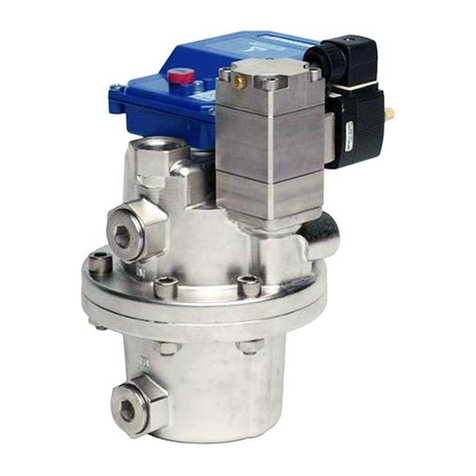
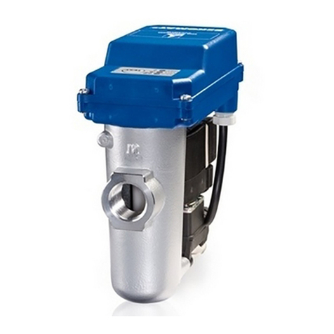
Beko BEKOMAT 33iU Owner's manual

EN
BEKOMAT®33iU / 33iU CO
01-4244
Original installation and operation manual
> BM33iU
> BM33iU CO

Table of contents
1. Notes about the documentation.....................................................................................................5
1.1 Contact ......................................................................................................................................5
1.2 Information about this installation and operation manual.....................................................5
2. Safety................................................................................................................................................6
2.1 Use .............................................................................................................................................6
2.1.1 Intended use.......................................................................................................................................6
2.1.2 Reasonably foreseeable inappropriate use................................................................................. 7
2.2 Responsibility of the operating company ................................................................................7
2.3 Target group and personnel......................................................................................................8
2.4 Explanation of the safety symbols used...................................................................................9
2.5 Safety and warning notices.................................................................................................... 10
2.5.1 Safe operation..................................................................................................................................10
2.5.2 Pressurised systems .......................................................................................................................10
2.5.3 Electric voltage ................................................................................................................................11
2.5.4 Transport and storage....................................................................................................................11
2.5.5 Installation........................................................................................................................................11
2.5.6 Maintenance ....................................................................................................................................12
2.5.7 Handling hazardous substances..................................................................................................12
2.5.8 Use of spare parts, accessories or materials ............................................................................13
2.6 Warning notices ..................................................................................................................... 13
3. Product information ..................................................................................................................... 14
3.1 Product overview ................................................................................................................... 14
3.2 Exploded drawing................................................................................................................... 15
3.3 Function description .............................................................................................................. 16
3.4 Modbus function .................................................................................................................... 17
3.4.1 Default interface parameters.......................................................................................................17
3.4.2 Byte sequence..................................................................................................................................17
3.4.3 Implemented functions .................................................................................................................17
3.4.3.1 Read Input Registers (0x04) ........................................................................................18
3.4.3.2 Read Device Identication (0x2B / 0x0E).................................................................19
3.4.3.3 Changing interface parameters ..................................................................................20
3.4.4 Error messages.................................................................................................................................21
3.5 Type plate ............................................................................................................................... 21
3.6 Scope of delivery ................................................................................................................... 22
BEKOMAT®33iU / 33iU CO Original installation and operation manual
2 | 68

4. Technical data ............................................................................................................................... 23
4.1 Operating parameters ........................................................................................................... 23
4.2 Storage and transportation parameters ............................................................................... 24
4.3 Materials................................................................................................................................. 24
4.4 Dimensions............................................................................................................................. 24
4.5 Screw fastening torques ........................................................................................................ 25
4.6 Installation dimensions.......................................................................................................... 26
4.7 Terminal diagram ................................................................................................................... 26
5. Transport and storage................................................................................................................... 27
5.1 Transport ................................................................................................................................ 27
5.2 Storage.................................................................................................................................... 27
6. Assembly ....................................................................................................................................... 28
6.1 Warning notices ..................................................................................................................... 28
6.2 Assembly conditions .............................................................................................................. 29
6.3 Assembly work ....................................................................................................................... 31
7. Electrical installation .................................................................................................................... 34
7.1 Warning notices ..................................................................................................................... 34
7.2 Connection work .................................................................................................................... 35
7.2.1 Single device connection...............................................................................................................35
7.2.2 Connecting multiple Modbus devices (series connection)...................................................37
8. Commissioning.............................................................................................................................. 39
8.1 Warning notices ..................................................................................................................... 39
8.2 Commissioning work.............................................................................................................. 40
9. Operation ...................................................................................................................................... 41
9.1 Warning notices ..................................................................................................................... 41
9.2 Operating states .................................................................................................................... 42
10. Maintenance ............................................................................................................................... 44
10.1 Warning notices ................................................................................................................... 44
10.2 Maintenance schedule......................................................................................................... 45
10.3 Maintenance work ............................................................................................................... 45
10.3.1 Changing the Service-Unit .........................................................................................................45
10.3.2 Functional test...............................................................................................................................53
10.3.3 Visual inspection...........................................................................................................................54
10.3.4 Leakage test...................................................................................................................................54
10.3.5 Cleaning ..........................................................................................................................................54
Original installation and operation manual BEKOMAT®33iU / 33iU CO
3 | 68

Table of contents
11. Consumables, accessories and spare parts................................................................................ 55
11.1 Order information................................................................................................................ 55
11.2 Accessories........................................................................................................................... 55
11.3 Spare parts............................................................................................................................ 56
12. Decommissioning ....................................................................................................................... 57
12.1 Warning notices ................................................................................................................... 57
12.2 Decommissioning work ....................................................................................................... 58
13. Dismantling................................................................................................................................. 59
13.1 Warning notices ................................................................................................................... 59
13.2 Dismantling work................................................................................................................. 59
14. Disposal....................................................................................................................................... 61
14.1 Warning notices ................................................................................................................... 61
14.2 Disposal of operational materials and components........................................................... 62
15. Troubleshooting.......................................................................................................................... 63
16. Appendices.................................................................................................................................. 64
16.1 Approval certicates and declarations of conformity........................................................ 64
16.2 Declaration of Conformity................................................................................................... 65
17. Notes ........................................................................................................................................... 67
BEKOMAT®33iU / 33iU CO Original installation and operation manual
4 | 68

1. Notes about the documentation
This documentation contains all the necessary steps for use of the product and the accessories.
1.1 Contact
Manufacturer Customer service and tools
BEKO TECHNOLOGIES GmbH
Im Taubental 7 | 41468 Neuss
Tel. + 49 2131 988 - 1000
www.beko-technologies.com
BEKO TECHNOLOGIES GmbH
Im Taubental 7 | 41468 Neuss
Tel. + 49 2131 988 - 1000
www.beko-technologies.com
INFORMATION Country-specic manufacturer representation
i
You can contact the country-specic manufacturer's representative via the address listed
in the address section on the rear cover or by using the contact form on the manufacturer's
website.
1.2 Information about this installation and operation manual
INFORMATION Copyright protection!
i
The contents of the installation and operation manual in the form of text, gures,
illustrations, photographs, technical drawings, diagrams and other representations are
protected by the copyright of the manufacturer. This applies especially to duplication,
reproduction, microlming and storage as well as processing in electronic systems.
Publication date Revision Version Reason for amendment Scope of amendment
18 May 2021 01 00 Editorial revision Spelling mistakes corrected and
spare part information added
30 June 2021 02 00 Change in technical data Change in technical data
08 Octobre 2021 03 00 Change of housing class Chapter 3.5 and 4.1
The installation and operation manual, hereinafter referred to as the manual, must always be kept close to the product
and be in a permanently legible condition.
The manual must be handed over along with the product if it is sold or passed on.
NOTE Follow the instructions given in the manual!
This manual contains all the basic information required for safe operation of the product and
must be read before any actions are performed. Otherwise personal and material hazards as well
as malfunction and device failure are possible.
Original installation and operation manual BEKOMAT®33iU / 33iU CO
5 | 68

2. Safety
2.1 Use
The BEKOMAT®33iU / 33iU CO, also referred to the following as product or BEKOMAT®, is an electronically level-
controlled condensate drain used for discharging condensate in pressurised systems. The BEKOMAT®is able to drain
condensate at operating pressure with no pressure loss.
2.1.1 Intended use
Any use of this system other than the use described in this manual is hereby deemed to be non-intended and can cause a
hazard for the safety of people and the environment.
The following must be noted for intended use:
• Read and follow the manual.
• Only use the product and the accessories in indoor areas.
• Only use the product and accessories within the operating parameters given in the technical data and the agreed
delivery conditions.
• Only operate the product and accessories with media which are free of caustic, aggressive, corrosive, toxic,
ammable, oxidising or inorganic components.
In cases of doubt an analysis must be carried out.
• Only use the product and accessories in surroundings where splash water is the maximum possible water exposure
that can occur. The splash water must be free of corrosive components.
• Only use the product and accessories in areas which are free of toxic and corrosive chemicals and gases.
• Only use the product and accessories within the piping system designed for the technical data with appropriate
connections, pipe diameters and assembly clearance.
• Only use the product and accessories outside potentially explosive atmospheres.
• Only use the product and accessories away from direct solar radiation and heat sources as well as areas subject to
frost.
• Only combine the product and accessories with the products and components named and recommended by
BEKO TECHNOLOGIES in the manual.
• Adhere to the prescribed maintenance schedule.
Before using the product and the accessories, the operating company must make sure that all conditions and
prerequisites for intended use are given.
The product and the accessories have been exclusively designed for stationary use in a commercial or industrial area. All
of the assembly, installation, operation, maintenance, disassembly and disposal work described may only be performed
by qualied skilled technical personnel.
BEKOMAT®33iU / 33iU CO Original installation and operation manual
6 | 68

2.1.2 Reasonably foreseeable inappropriate use
Reasonably foreseeable inappropriate use is deemed to have occurred if the product or the accessories are used in any
other way than that described in the chapter "Intended use". Reasonably foreseeable inappropriate use includes the use
of the product or the accessories in a manner not intended by the manufacturer or supplier but which may result from
foreseeable human behaviour.
Reasonably foreseeable inappropriate use includes:
• The execution of any kind of modication, in particular constructive and process-technology related interventions.
• The suspension, bridging or non-application of existing or recommended safety equipment.
• Using the product and accessories in piping systems with carbon dioxide as the operating medium.
This list is not exhaustive as not all possible inappropriate use can be foreseen in advance. If the operating company
is aware of any inappropriate use of the product or accessories which are not listed here, the manufacturer must be
informed immediately.
2.2 Responsibility of the operating company
The responsible operating company must ensure the following to prevent accidents, incidents and adverse eects on the
environment:
• Before all actions, check to ensure that the manual available does in fact belong to the product.
• The product and the accessories are used, serviced and repaired in accordance with the intended use.
• The product and accessories are only used with the recommended and fully operable safety equipment.
• All assembly, installation and maintenance work is carried out by qualied skilled technical personnel only.
• Personnel have the necessary personal protective equipment available and also use this equipment.
• Suitable technical safety measures are taken so that the permissible operating parameters are adhered to.
• Keep all safety symbols and the type plate on the product in a legible state. Replace damaged and illegible marking
immediately.
Original installation and operation manual BEKOMAT®33iU / 33iU CO
7 | 68

2.3 Target group and personnel
This manual addresses the personnel listed below who are involved with work on the product or the accessories.
INFORMATION Personnel requirements!
iThe personnel may not execute any actions on the product or the accessories when they are
under the inuence of drugs, medications, alcohol or other substances that may impair their
consciousness.
Operating personnel
Operating personnel are persons who are able to operate the product and the accessories safely on the basis of
knowledge of the manual and instruction at the product and accessories. Operating personnel can recognise possible
malfunctions and dangerous situations independently and arrange for corresponding measures.
Skilled technical personnel - transport and storage
Skilled technical personnel - transport and storage are people who, due to their training, professional experience and
qualications, have all the necessary skills to safely execute all actions in connection with the transport and storage of
the product, to instruct, to recognise possible dangerous situations independently and to execute measures to avoid
danger.
The capabilities include, in particular, experience with hoists, forklifts and lifting equipment and knowledge of local
laws, standards and guidelines relating to transport and storage.
Skilled technical personnel - compressed gas technology
Skilled technical personnel - compressed gas technology are people who, due to their training, professional experience
and qualication, possess all the necessary capabilities to safely execute actions, and instruct all actions related to
pressurised uids and systems, to independently foresee potential hazardous situations and implement appropriate
measures to avert any danger.
The capabilities include, in particular, experience in handling Measuring technology and control technology as well as
knowledge of the regionally applicable laws, standards and regulations for pressurised systems.
Skilled technical personnel - electrical engineering
Skilled technical personnel - electrical engineering are people who, due to their training, professional experience and
qualication, have all the necessary capabilities to safely execute all actions related to electricity, to instruct and to
independently foresee potential hazardous situations and take appropriate measures to avoid any danger.
The capabilities include, in particular, experience in handling electric voltage plants, measurement and
control technology as well as knowledge of the regionally applicable laws, standards and regulations
(e.g. VDE 0100 / IEC 60364 / ATEX) applicable for handling electrical technology.
Skilled technical personnel - customer service
Skilled technical personnel - customer service are people who have the skills and qualications of the skilled personnel
denitions named above. Skilled technical personnel - customer service must have documented proof of training for all
work on the product and be authorised.
BEKOMAT®33iU / 33iU CO Original installation and operation manual
8 | 68

2.4 Explanation of the safety symbols used
The symbols used below indicate safety-relevant and important information which must be adhered to when handling
the product and to ensure safe and optimum operation.
Symbol Description / explanation
General warning symbol (danger, warning, caution)
Warning: pressurised system
Warning: electric voltage
Note the installation and operating manual
General note
Wear safety footwear
Use protective gloves (cut-proof and liquid-resistant)
Wear safety goggles with side shields
i
General information
Original installation and operation manual BEKOMAT®33iU / 33iU CO
9 | 68

2.5 Safety and warning notices
This chapter provides an overview of all the important safety aspects for personal protection as well as for the safe and
problem-free operation of the product and accessories.
The following chapters list the dangers posed by this product and the accessories even with intended use. To minimise
the risk of personal injury and damage to property and to avoid dangerous situations, observe the safety instructions
listed and adhere to the warning notices in the other chapters of this manual.
Basic warning notices and the necessary qualications of skilled technical personnel are always listed at the beginning of
the chapter in the “Warning notices” section.
Warning notices related to specic actions are printed directly before potentially hazardous procedures or sequences of
actions.
2.5.1 Safe operation
Commissioning and operating the product and accessories outside the permissible limits and operating parameters may
result in serious personal injuries or death. Unauthorised interference and unauthorised modications of the product
and accessories may lead to serious personal injuries or death.
To guarantee safe operation of the product and accessories, observe the following points:
• Use suitable protective equipment during all work on the product or accessories.
• Adhere to the limits and operating parameters specied on the type plate and in the manual.
• Adhere to the assembly conditions and ambient conditions.
• Check whether the permissible operating parameters have been amended or restricted by the use of accessories.
• Adhere to the maintenance intervals.
2.5.2 Pressurised systems
Contact with quickly or suddenly escaping uids or bursting plant parts may result in serious personal injuries or death.
For the safe handling of pressurised systems, observe the following points:
• Set up a safety area around the working area during assembly, installation, maintenance and repair work.
• Before starting work, depressurise the pressurised system and secure it against unintentional pressurisation.
• Before pressurisation, check all system pipe connections for leak tightness and tighten if necessary.
• Slowly pressurise the system.
• Avoid pressure blows and high dierential pressures.
• Compensate any vibrations occurring in the pipe network by using vibration dampers.
BEKOMAT®33iU / 33iU CO Original installation and operation manual
10 | 68

2.5.3 Electric voltage
Contact with live components may result in serious personal injuries or death.
To ensure the safe handling of live components, observe the following points:
• Set up a safety area around the working area during all installation and repair work.
• Before starting work, de-energise the product and accessories and secure them against being switched back on again
unintentionally.
• Only connect the product and the accessories to the voltage supply if they are undamaged.
• Adhere to all applicable regulations (e.g. VDE 0100 / IEC 60364 / ATEX) during installation.
• Connect the protective conductor (earth connection) according to regulations.
• Only operate the product and accessories with the cover complete and closed or the housing closed.
2.5.4 Transport and storage
Inappropriate transport or storage may result in personal injury or damage to property.
For safe transport and storage of the product and accessories, observe the following points:
• Use personal protective equipment during all work with packaging material.
• Handle packaging, the product and accessories carefully.
• Transport and handle the packaged product and accessories according to the markings on the packaging (note lifting
gear attachment points, the centre of gravity and alignment e.g. keep vertical, do not throw etc.).
• Only use proper means of transport and lifting equipment that is in proper working order.
• Always adhere to the permissible transport and storage parameters.
• Store the product and accessories only outside of areas exposed to direct sunlight and heat sources.
2.5.5 Installation
Inappropriate assembly or electrical installation of the product and accessories may result in personal injury and damage
to property as well as impair operation.
For safe assembly and electrical installation, observe the following points:
• Install the product, the accessories, and all parts and materials used so that they are not subject to mechanical
tension.
• Check all plug-type connections for a correct t.
• Avoid a stumbling hazard by routing cables and hoses accordingly.
• Avoid mechanical strain on the cables.
• Fix and fasten hoses in such a way that they cannot ap around.
• Install the feed lines and drain lines as xed pipes.
Original installation and operation manual BEKOMAT®33iU / 33iU CO
11 | 68

2.5.6 Maintenance
Inappropriate completion of maintenance and repair work may result in serious personal injuries or death.
For safe maintenance and repair, observe the following points:
• Use suitable protective equipment during all maintenance and repair work on the product or accessories.
• Set up a safety area around the working area during all maintenance and repair work.
• Before starting work, depressurise the pressurised product and accessories and secure them against unintentional
pressurisation.
• Before starting work, de-energise the product and accessories and secure them against being switched back on again
unintentionally.
• Only use materials approved for the respective application.
• Use only suitable tools that are in proper working order.
• Only use cleaned pipes and hoses that are free of dirt and corrosion.
• Never use abrasive or aggressive detergent or solvents which could damage the outer coating (e.g. markings, type
plate, corrosion protection, etc.).
• Never clean the device with hard or pointed implements.
• Use an anti-static, damp cloth for cleaning the outside.
• Observe the regionally applicable hygiene regulations.
• Pay attention to cleanness and tidiness during maintenance and repair work. Prevent contamination from entering
the opened product or accessories. Store the disassembled components and accessories directly in a safe place.
• After completing maintenance and repair work, remove all of the tools and cleaning media used as well as all parts
that are no longer needed from the work area.
• Only dispose of the product and accessories when cleaned and freed of any media residue.
• Dispose of all components, parts, operating and auxiliary materials as well as cleaning media professionally and in
accordance with regional legal specications and regulations.
• Dispose of electrical and electronic components through a specialist waste disposal company or return to
BEKO TECHNOLOGIES.
2.5.7 Handling hazardous substances
Contact with condensate containing substances which endanger health and the environment can pose a health hazard,
causing irritation and/or damage to the eyes, skin and mucous membranes. In addition, polluted condensate must be
prevented from entering the sewerage system, waters or the ground.
For the safe handling of polluted condensate the following points must be observed:
• Use suitable protective equipment when handling condensate.
• Pick up and dispose of any leaking or spilled condensate in accordance with applicable regional laws and
requirements.
BEKOMAT®33iU / 33iU CO Original installation and operation manual
12 | 68

2.5.8 Use of spare parts, accessories or materials
The use of incorrect spare parts, accessories or materials, as well as auxiliary and operating materials, may result in death
or serious injury. Malfunction and device failure as well as material damage can occur.
• Only use undamaged original parts, auxiliary and operating materials which are specied by the manufacturer to
complete all work.
• Only use the materials approved for the respective application and suitable tools in proper working order.
• Only use cleaned pipes that are free of dirt and corrosion.
• Only use electric components and materials that comply with regionally applicable specications and regulations
(standards, directives etc.) for electrical safety.
2.6 Warning notices
Warning notices warn against dangers when handling the product and accessories.
In order to prevent accidents, personal injury and damage to property as well as impairments during operation, it is
essential to adhere to the warning notices.
Structural set up:
SIGNAL WORD Type and source of danger!
Symbol
Possible consequences if the danger is ignored
• Measure to prevent the danger
Signal words:
DANGER Imminent hazard
Consequences of non-compliance: Death or serious personal injury
WARNING Imminent hazard
Consequences of non-compliance: Death or serious personal injury are possible
CAUTION Potential hazard
Consequences of non-compliance: Personal injury or damage to property are possible
NOTE Additional notes
Consequences of non-compliance: Damage to property, malfunction and device failure are
possible. No hazard to people or endangerment of safe operation.
Original installation and operation manual BEKOMAT®33iU / 33iU CO
13 | 68

3. Product information
3.1 Product overview
G
F
A B C
H
D
E
Item Description / explanation Item Description / explanation
[A] Control unit, complete [E] Condensate inlet (only when a venting line is
used at the same time)
[B] Control panel [F] Condensate discharge
[C] Condensate inlet, vertical [G] Right cable gland
[D] Condensate inlet, horizontal [H] Left cable gland
BEKOMAT®33iU / 33iU CO Original installation and operation manual
14 | 68

3.2 Exploded drawing
Item Description / explanation Item Description / explanation
[1] Screw M3.5 x 10 [13] O-ring 18.5 x 2 mm
[2] Top cover [14] Condensate collecting container
[3] Moulded seal [15] Flat gasket
[4] Sensor board [16] Locking screw G1/2
[5] Bottom cover [17] Plug G1/2
[6] Screw tting [18] O-ring 48.9 x 2.62 mm
[7] Plug [19] Condensate collecting container cover
[8] Design shell (optional) [20] Cylinder head screw hexagon socket M6 x 16
[9] Hose connection [21] Flat gasket
[10] Plug [22] Locking screw G1/2
[11] Cross-slot screw M6 x 16 [23] Sealing mat
[12] Service-Unit [24] O-ring 8 x 4 mm
6
7
11
12
23
24
2
3
4
5
89
10
13
14
15
16
17
18
19
20
21
22
20
1
Original installation and operation manual BEKOMAT®33iU / 33iU CO
15 | 68

3.3 Function description
Illustration Description / explanation
K
CL
D
The condensate ows via the vertical condensate
inlet [C] or the horizontal condensate inlet [D] into the
BEKOMAT®and collects in the collecting container [K].
The lling level in the collecting tank [K] is continuously
monitored by a capacitive sensor in the sensor tube [L].
F
M
N
K
Once the condensate has reached the maximum ll level,
the pilot valve [M] is activated using the controller.
The pilot valve [M] activates, and the area above the
membrane [N] is depressurised.
The membrane [N] lifts o of the valve seat and the
excess pressure in the collecting container [K] presses the
condensate into the condensate discharge [F].
L
F
M
N
K
When the sensor in the sensor tube [L] is no longer
covered by condensate, the controller of the pilot
valve [M] activates and pressure builds up above the
membrane [N].
The membrane [N] is pressed against the valve seat and
the condensate discharge [F] is sealed tightly.
The switching cycle starts again with the inlet of
condensate.
BEKOMAT®33iU / 33iU CO Original installation and operation manual
16 | 68

3.4 Modbus function
The BEKOMAT®has an integrated Modbus which can be used to read out the operating parameters and device
information.
The BEKOMAT®is operated using the client-server system with operating mode Modbus-RTU.
Data is transmitted via an RS485 interface in binary format.
3.4.1 Default interface parameters
The BEKOMAT®is available via Modbus 10 seconds after start-up with the following interface parameters.
Value Parameter
Baud rate 19200
Data bits 8
Stop bits 1
Parity even
Client address 247
3.4.2 Byte sequence
Data type Modbus register Division
oat 2 Register ABCD
u32 2 Register ABCD
u16 1 Register AB
u8 1 Register A
u8 B
3.4.3 Implemented functions
The following Modbus functions are supported:
1. Read Input Registers (0x04)
2. Read Device Identication (0x2B / 0x0E)
3. Changing interface parameters
Original installation and operation manual BEKOMAT®33iU / 33iU CO
17 | 68

3.4.3.1 Read Input Registers (0x04)
Modbus
address Contents Description / explanation Data type
1116 Main Timer Hi-Word Operating hours counter [h] u32
1117 Main Timer Lo-Word
1102 Main Counter Hi-Word Counter for switching cycles u32
1103 Main Counter Lo-Word
1540 Temperature Hi-Word CPU Temperature [°C] oat
1541 Temperature Lo-Word
1542 Temperature Hi-Word CPU Temperature [°F] oat
1543 Temperature Lo-Word
1544 Voltage Hi-Word Supply Voltage [V] oat
1545 Voltage Lo-Word
1700 Status POWER LED
LED o = 0
LED 100 % = 1
LED 50 % = 2
u16
1701 Status Error LED
LED o = 0
LED 100 % = 1
LED 50 % = 2
u16
1760 Main Button State
Status TEST button
On = 1
O = 0
u16
3103 Remaining Time Hi-Word Remaining service time [%] oat
3104 Remaining Time Lo-Word
3105 Remaining Counts Hi-Word Remaining switching cycles [%] oat
3106 Remaining Counts Lo-Word
3200 Error Flags
All Error Flags
Bit 1 = Error1 Flag
Bit 2 = Error2 Flag
Bit 3 = Error3 Flag
Bit 4 = Error4 Flag
Bit 5 = Error5 Flag
Bit 6 = Error6 Flag
u16
3201 Error1 Flag
Code Flash faulty
1 = Error active
0 = Error inactive
u16
3202 Error2 Flag
Conguration faulty
1 = Error active
0 = Error inactive
u16
3203 Error3 Flag
Device not adjusted
1 = Error active
0 = Error inactive
u16
BEKOMAT®33iU / 33iU CO Original installation and operation manual
18 | 68

Modbus
address Contents Description / explanation Data type
3204 Error4 Flag
Hardware faulty
1 = Error active
0 = Error inactive
u16
3205 Error5 Flag
Alarm
1 = Error active
0 = Error inactive
u16
3206 Error6 Flag
Voltage supply drop during discharge
1 = Error active
0 = Error inactive
u16
3.4.3.2 Read Device Identication (0x2B / 0x0E)
The advanced function (MEI Type) Read Device Identication (0x2B / 0x0E), can be used to read out the following
device-specic data.
Object
ID
Item name
(Modbus
specication)
Description / explanation Examples Format
0x00 VendorName Manufacturer BEKO TECHNOLOGIES ASCII
0x01 ProductCode BEKO material number circuit
board 04023034 ASCII
0x02 MajorMinorRevision Software version numbers* APP V2.3.0 BBS V3.4.0 CFG V1.0.0 ASCII
0x03 VendorUrl BEKO website http://www.beko-technologies.
com ASCII
0x04 ProductName BEKO product name BEKOMAT ASCII
0x05 ModelName BEKO circuit board designation KA2C OL11 2044 ELV P i4.0 ASCII
0x06 UserApplicationName BEKO serial number circuit
board 1912720040 ASCII
0x80 n.a. Production: Circuit board test
date 03/01/2018/14:53:16/01/01/01 ASCII
0x81 n.a. Production: Circuit board
adjustment date 04/02/2018/08:25:44/01/01/01 ASCII
0x82 n.a. Production: Circuit board
calibration date 04/02/2018/08:25:44/01/01/01 ASCII
0x83 n.a. Production: free 04/02/2018/08:25:44/01/01/01 ASCII
0x85 n.a. BEKO material number
BEKOMAT®0004046022 ASCII
0x86 n.a. BEKO serial number BEKOMAT®0014345535 ASCII
0x87 n.a. Customer material number,
optional -- ASCII
* Legend: APP = application
BBS = BEKO basic software
CFG = Conguration
Original installation and operation manual BEKOMAT®33iU / 33iU CO
19 | 68

3.4.3.3 Changing interface parameters
INFORMATION BEKO TECHNOLOGIES conguration tools!
iBEKO TECHNOLOGIES recommends using the Software Integrator to change the interface
parameters. The software can be downloaded from the BEKO TECHNOLOGIES homepage
(see “1.1 Contact” on page 5).
To connect to a PC, BEKO TECHNOLOGIES recommends using the Integrator Hardware Kit
(for ordering information, see chapter “11.2 Accessories” on page 55).
This process is used to change interface parameters required for communication.
1. Write the value 0xAC1D (decimal: 44061) to Holding Register 0x1392 (Decimal: 5010).
2. Write the parameter to the Holding Register 0x07D0 (decimal: 2000).
Description / explanation
HighByte: See the following table
LowByte: Modbus Client address 1 … 246
Example value: 0x070A (decimal: 1802)
For interface parameters see table Index 0x07 (decimal: 7)
Client Address 0x0A (decimal: 10)
3. To save the settings, write the value 0xBA5E (decimal: 47710) to Holding Register 0x139C (Decimal: 5020).
4. Switch the product o and switch it back on again.
0The changes will go into eect approx. 10 seconds after the restart.
Parameter - HighByte Parameter - HighByte
Selection Baud
rate [Bd] Parity Stop Bit Selection Baud
rate [Bd] Parity Stop Bit
0x00 4800 No 2 0x0C 57600 No 2
0x01 4800 Even 1 0x0D 57600 Even 1
0x02 4800 Odd 1 0x0E 57600 Odd 1
0x03 9600 No 2 0x0F 76800 No 2
0x04 9600 Even 1 0x10 76800 Even 1
0x05 9600 Odd 1 0x11 76800 Odd 1
0x06 19200 No 2 0x12 115200 No 2
0x07 19200 Even 1 0x13 115200 Even 1
0x08 19200 Odd 1 0x14 115200 Odd 1
0x09 38400 No 2
0x0A 38400 Even 1
0x0B 38400 Odd 1
BEKOMAT®33iU / 33iU CO Original installation and operation manual
20 | 68
This manual suits for next models
3
Table of contents
Other Beko Industrial Equipment manuals

Beko
Beko BEKOMAT 21 User guide

Beko
Beko BEKOSPLIT 14S User guide

Beko
Beko BEKOMAT 31U F User guide

Beko
Beko DRYPOINT M DM 08-14 R User guide

Beko
Beko BEKOSPLIT 14S User guide

Beko
Beko BEKOMAT 3 E Ex User manual

Beko
Beko BEKOMAT 13 User guide

Beko
Beko DRYPOINT M DM 40-61 C User guide

Beko
Beko BEKOMAT 12 Owner's manual

Beko
Beko BEKOMAT 8 User manual