Altana BYK wave-scan 3 ROBOTIC User manual

Operating Instructions
wave-scan 3 ROBOTIC
Measure what you see

BYK-Gardner GmbH
301 200 141 E 2010 wave-scan 3 ROBOTIC 2
© Copyright 2020 BYK-Gardner GmbH
All rights reserved

BYK-Gardner GmbH Table of Contents
301 200 141 E 2010 wave-scan 3 ROBOTIC 3
Table of Contents
1 Introduction.................................................................................................................................. 5
1.1 Safety Instructions ............................................................................................................................... 6
1.2 Declaration of Conformity.................................................................................................................. 8
1.3 Handling Instructions .......................................................................................................................... 8
1.4 Prerequisites ........................................................................................................................................ 8
2 Hardware....................................................................................................................................... 9
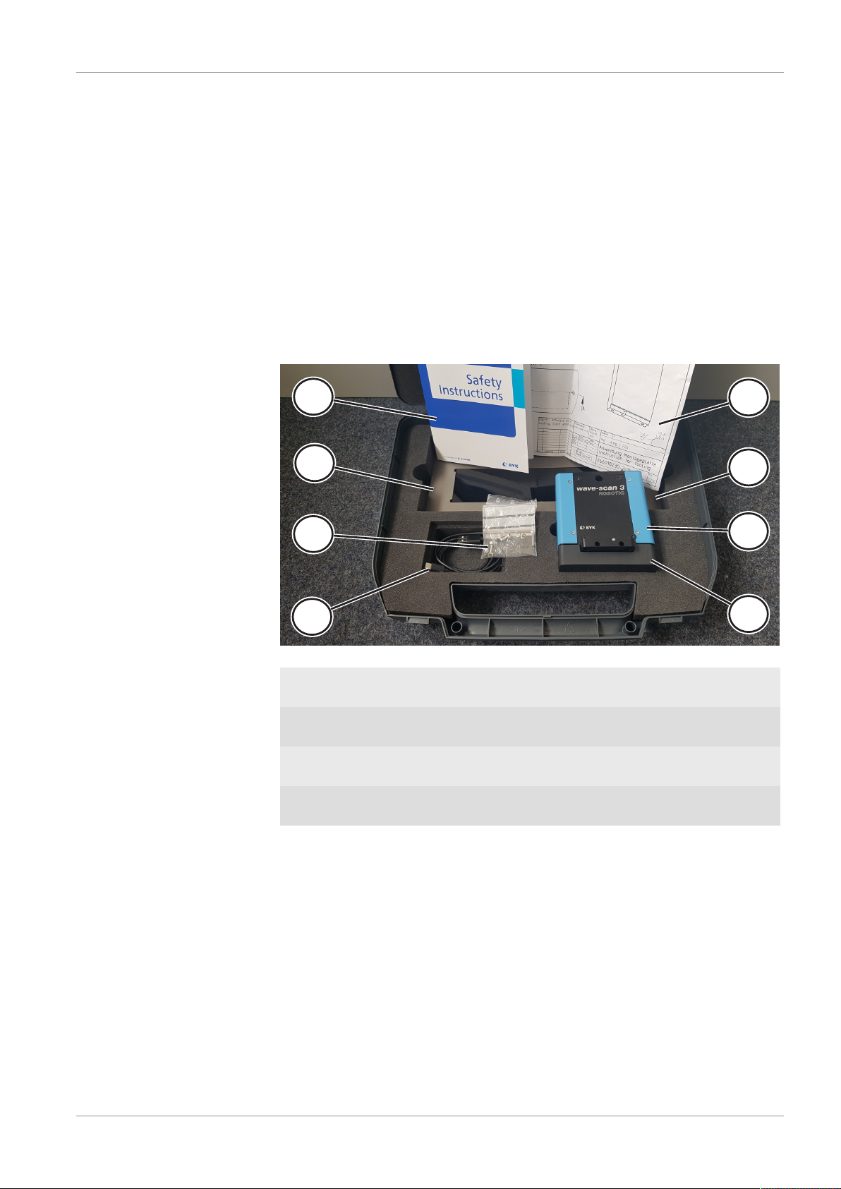
2.1 Delivery Content.................................................................................................................................. 9
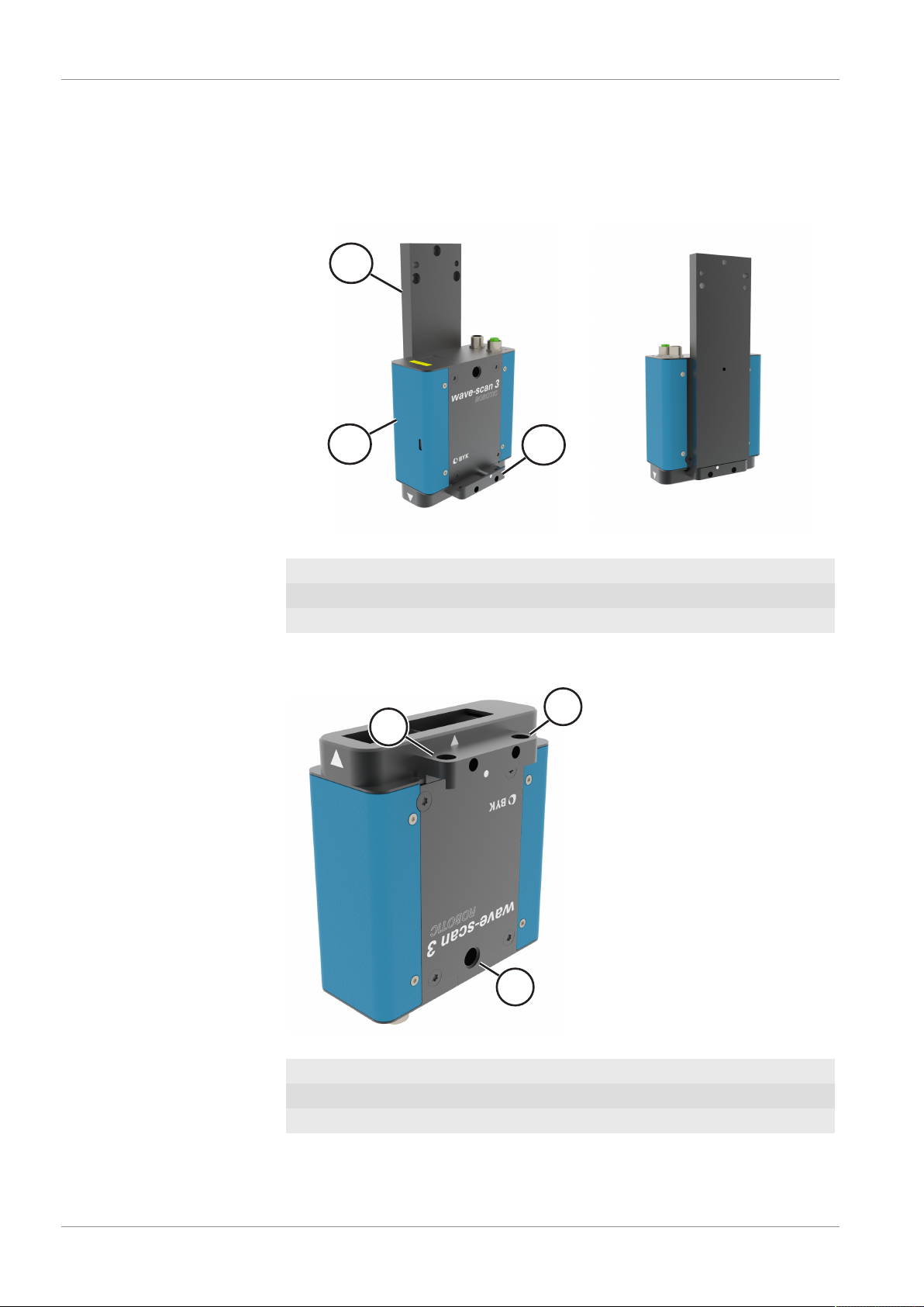
2.2 Mounting Board .................................................................................................................................. 10
2.3 Power Supply ....................................................................................................................................... 11
2.4 Status LEDs........................................................................................................................................... 12
3 Cabling .......................................................................................................................................... 13
3.1 Application Example ........................................................................................................................... 13
3.2 Power Cables ....................................................................................................................................... 14
3.3 Data Cables .......................................................................................................................................... 16
3.4 USB Cable............................................................................................................................................. 18
4 Operation ...................................................................................................................................... 19
4.1 Software Installation........................................................................................................................... 19
4.2 Firmware Update................................................................................................................................. 19
4.3 Device Configuration .......................................................................................................................... 20
4.3.1 Driver Installation ..................................................................................................................... 20
4.3.2 Device Connection.................................................................................................................... 22
4.3.3 Device Test ................................................................................................................................ 23
4.4 Productive System ............................................................................................................................... 24
5 Checking........................................................................................................................................ 25
5.1 Principle ............................................................................................................................................... 25
5.2 Mounting ............................................................................................................................................. 25
5.3 Procedure............................................................................................................................................. 26
6 Appendix....................................................................................................................................... 27
6.1 Cleaning and Maintenance................................................................................................................. 27
6.1.1 Cleaning the Test Tile............................................................................................................... 27
6.1.2 Usage of Reference Tile ........................................................................................................... 27
6.2 Delivery Notes...................................................................................................................................... 28
6.2.1 Product Highlights.................................................................................................................... 28
6.2.2 Product Features....................................................................................................................... 28
6.2.3 Delivery Content....................................................................................................................... 28
6.2.4 Download Links ........................................................................................................................ 29
6.2.5 Accessories List.......................................................................................................................... 29
6.3 Error Messages..................................................................................................................................... 30
6.4 System Requirements .......................................................................................................................... 30
6.5 Technical Data ..................................................................................................................................... 31
6.5.1 Measuring Data ........................................................................................................................ 31
6.5.2 General Data............................................................................................................................. 31

1 | Introduction BYK-Gardner GmbH
4 wave-scan 3 ROBOTIC 301 200 141 E 2010

BYK-Gardner GmbH Introduction | 1
301 200 141 E 2010 wave-scan 3 ROBOTIC 5
1 Introduction
This instruction manual is an important part of this instrument. It contains
essential information about setting up, placing in service and use. If you
pass the device on to another user, please ensure that the instruction man-
ual is included with the instrument. The manual must be studied carefully
before working with the equipment. Please contact your regional service
office if you have any questions or require additional information about
the device.
The technology and fittings are based on state-of-the art optic and elec-
tronic technology. New developments and innovations are constantly being
integrated into the equipment. Thus, the diagrams, dimensions, and techni-
cal data used in this manual may have changed as a result of adapting the
device to new information and improvements.
© Copyright 2020 BYK-Gardner GmbH
All rights reserved
No portion of the software, documentation or other accompanying materi-
als may be translated, modified, reproduced, copied or otherwise dupli-
cated (with the exception of a backup copy), or distributed to a third party,
without prior written authorization from BYK-Gardner GmbH. In any case,
this requires the prior written consent of BYK-Gardner.
BYK-Gardner GmbH offers no guarantee that the software will function
without error or that the functions incorporated therein can be executed in
all applications and combinations selected by you.
No liability other than as provided by law is assumed for direct or indirect
damage sustained in association with the use of the instrument, the soft-
ware or documentation.
BYK-Gardner GmbH reserves the right to update the software and written
documentation without prior notice.
www.byk-instruments.com

1 | Introduction BYK-Gardner GmbH
6 wave-scan 3 ROBOTIC 301 200 141 E 2010
1.1 Safety Instructions
No claims of product liability or warranty can be honored if the device is
not operated in accordance with the operating instructions and the instruc-
tions on the instrument.
The measurement unit is a class 1 laser product. The label shown below is
on the base of the measurement unit.
Caution!
Since the laser beam used for sampling can penetrate your eye and cause
injuries, never dismantle the instrument and never look directly into the
measurement aperture when the device is turned on.
If you use the unit and accessories properly, there are no hazards to fear –
none of a mechanical nature and none caused by electrical shock.
The following paragraphs contain information about the safe use of the
device.
Use only original accessories provided by the manufacturer. See “Delivery
Notes” and “Technical Data” for further information.
Avoid exposure to continuous humidity and condensation. See “Technical
Data” for further information. Avoid splashing with water, chemicals or
other liquids.
Never attempt to make any repairs to the instrument, neither mechanical
nor electrical. Please consult our Technical Customer Service.

BYK-Gardner GmbH Introduction | 1
301 200 141 E 2010 wave-scan 3 ROBOTIC 7
Only devices that meet the requirements for low-voltage safety may be
connected to the control interface (green).
For operation with the external power supply, care should be taken to en-
sure the nominal voltage of the power supply unit (see the manufacturer’s
plate on the power supply unit) matches the voltage supplied by the power
outlet.
The measurement device may be disconnected from the power supply as
follows:
By disconnecting the power plug (black) from the device.
You will find the technical data on the manufacturer’s plate and in the sec-
tion “Technical Data”.
Defects and extraordinary loads
If safe operation can no longer be presumed, shut down the device and se-
cure it against unintended operation.
The device must be presumed unsafe to operate:
• if visible damage is evident,
• if the instrument is no longer working,
• if it has been stored for long periods under adverse conditions,
• after harsh treatment during shipping.
Additional information on disposal
This symbol means: Do not dispose of this product together with your
household waste. Please refer to the information of your local community
or contact our dealers regarding the proper handling of end-of life electric
and electronic equipment.
Recycling of this product will help to conserve natural resources and pre-
vent potential negative consequences for the environment and human
health caused by inappropriate waste handling

1 | Introduction BYK-Gardner GmbH
8 wave-scan 3 ROBOTIC 301 200 141 E 2010
1.2 Declaration of Conformity
We,
BYK-Gardner GmbH
Lausitzer Strasse 8
D-82538 Geretsried
declare, that this instrument complies with the requirements of the follow-
ing EU directives:
• 2014/30/EU - Electromagnetic Compatibility
• 2014/35/EU - Low Voltage
The following harmonized standards were applied:
• EN 60825-1:2007
• EN 61010-1:2010
• EN 61326-1:2013
Geretsried, November 13, 2019
Frank R. Wagner
Managing Director
1.3 Handling Instructions
The measurement unit contains sensitive precision optical and electronic
parts. Do not drop it and protect it from being bumped or jostled!
Do not hold the unit by the measurement aperture or allow any foreign
objects to get into this opening.
Do not expose the unit to direct sunlight for extended periods of time. Do
not store it in a hot or dusty environment. The case that comes with the
unit offers the best protection when the unit is being stored.
Avoid prolonged exposure to high relative humidity and do not allow wa-
ter to form from condensation, see Technical Data [}31].
Protect the measuring unit from moisture, chemicals and corrosive vapors.
1.4 Prerequisites
In order to operate the instrument basic understanding of following topics
is recommended:
• Instrument wave-scan 3 / 3 dual for manual measurements (option)
• Software smart-process to monitor the measurement results
• Software smart-robotic to configure and control the device

BYK-Gardner GmbH Hardware | 2
301 200 141 E 2010 wave-scan 3 ROBOTIC 9
2 Hardware
Before operating the instrument for the first time, please read the Operat-
ing Instructions and take particular notice of the Safety Instructions.
Unpack the instrument and check the delivery for completeness.
2.1 Delivery Content
The system comes complete with: Measurement unit, cover, test tile, certifi-
cate and safety instructions. Also included are screws and a drawing for the
robot mounting board.
The items listed below are contained in the transportation case. Please con-
tact BYK-Gardner, if any item is missing or damaged. See also Delivery
Notes [}28].
1
2
3
4
5
6
7
8
Illustration1: Delivery content
1 Safety instructions and retrace-
able certificate
5 Drawing for mounting board
2 Checking tile for instrument
test
6 Cleaning towel for checking
tile
3 Screws and tool for mounting
board
7 Measurement unit
4 USB cable type A / C for initial-
ization
8 Protective cap
The power and communication cables - see Cabling [}13] - are outside the
transportation case, but inside the delivery packaging.

2 | Hardware BYK-Gardner GmbH
10 wave-scan 3 ROBOTIC 301 200 141 E 2010
2.2 Mounting Board
A mounting board is required to mount the instrument to the robot arm.
This board is not part of the delivery. A drawing, that contains all dimen-
sions for the production of the mounting board, is enclosed with each in-
strument.
1
23
Illustration2: Mounting board with wave-scan 3 ROBOTIC
1 Mounting board
2 Mounted instrument
3 Fixing bar
The measuring instrument is fixed at the mounting board with three screws
(part of the delivery) on the position given below.
12
3
Illustration3: Mounting of wave-scan 3 ROBOTIC
1 Mounting position 1 - instrument bottom
2 Mounting position 2 - instrument bottom
3 Mounting position 3 - instrument top
The millings at the fixing bar and a pen matching into the deepening pro-
vides for a distinctive attachment.

BYK-Gardner GmbH Hardware | 2
301 200 141 E 2010 wave-scan 3 ROBOTIC 11
During the measurement, a distance of 15 mm ± 2 mm to the surface is to
be kept.
The angle-deviation of the perpendiculars on the surface can amount to at
most 2° to all sides.
NOTICE
The mounting can be done on the left or on the right side of the measure-
ment unit. The protruding element on the side not used can be screwed off
(two small screws).
2.3 Power Supply
The instrument is supplied by an external AC / DC power adapter, which is
not part of the delivery.
1
2
Illustration4: Interface connectors of wave-scan 3 ROBOTIC
1 Power supply is provided via a black 8-pole plug.
2 Data transmission is provided via a green 4-pole plug.
In order to connect the measuring instrument, first check the wiring and
the matching of the power supply. Subsequently you plug in the black plug
and switch on power.

2 | Hardware BYK-Gardner GmbH
12 wave-scan 3 ROBOTIC 301 200 141 E 2010
2.4 Status LEDs
The instruments has four Light Emitting Diodes (LEDs) for status indication.
4
3
2
1
Illustration5: Status LEDs of wave-scan 3 ROBOTIC
1 Lights in green whenever the device detects a valid link.
Blinks in green when CRS is active (high) indicating activity.
2 Lights in blue when the operating speed is 100 Mbps.
It is inactive when the operating speed is 10 Mbps or during line iso-
lation.
3 Indicates the status of the measurement:
• Lights in green during the measurement.
• Lights in red when measurement errors occur.
4 Lights in green when the power supply is connected.
If a mistake should happen during the measurement, it is signaled by a red
blinking light-emitting-diode (LED-3). The pertinent error code is shown at
the screen.

BYK-Gardner GmbH Cabling | 3
301 200 141 E 2010 wave-scan 3 ROBOTIC 13
3 Cabling
The delivery comprises the cables required for initialization and to connect
instrument on robot arm with PC:
•Power Cables [}14]
•Data Cables [}16]
•USB Cable [}18]
WARNING
To avoid instrument damage, only use the cables which are part of the de-
livery for connecting the instruments!
3.1 Application Example
Following picture gives an example how the cables can be placed in a robot
cell.
Illustration6: Example cabling in a robot cell
Yellow At robot arm: Torsion capable cable
Green For track chain: Standard cable
Red On the floor: Oil resistant cable
These three types of cables are provided for both power and data interface.

3 | Cabling BYK-Gardner GmbH
14 wave-scan 3 ROBOTIC 301 200 141 E 2010
3.2 Power Cables
The power interface is a black 8-pole plug. The power supply input is 24 V
; max. 0.75 A.
Illustration7: Polarity diagram for pins M12, 8-pin, A-coded, view pen side
Pin ROBOTIC
Power
Cable Color
4-pin M12-A
Cable Color
8-pin M12-A
1 Vin White White
2 Vin Yellow Yellow
3 NC Green
4 NC Brown
5 NC
6 GND
7 GND Green
8 GND Brown
M1 Shield
Following power cables are in the delivery.
1
2
3
Illustration8: Power cables
1 301 200 143: 8 m for robot - torsion capable
2 301 200 144: 10 m for drag chain
3 301 200 145: 20 m on floor - oil resistant
The delivery comprises cables and connectors. If necessary, a coupler can be
used to attach plugs on both sides to the floor. The product “Binder
0952400004” is recommended.

BYK-Gardner GmbH Cabling | 3
301 200 141 E 2010 wave-scan 3 ROBOTIC 15
Lappkabel 0028900 4-wire Lappkabel 0028900 4-wire Lappkabel 0029657 4-wire
Binder
99143281404
4-pol socket M12-A
Binder
99143281404
4-pol socket M12-A
Binder
99148881408
8-pol socket M12-A
Binder
99143181404
4-pol pins M12-A
Binder
99143181404
4-pol pins M12-A
20 m on flor - oil resistant
301 200 145 301 200 144
10 m for track chain
301 200 143
8 m for robot - torsion capable
Binder
0952400004
(coupler, option)
Illustration9: 301 200 142 Power cable complete for 7410
Products from following vendors are used:
•https://www.binder-connector.com
•https://www.lappkabel.com
Attention: Please heed tension and pin assignment precisely. The instru-
ment can be damaged without functional connection. No product liability
and guarantee claims can be put forward if the instrument is not properly
power supplied.

3 | Cabling BYK-Gardner GmbH
16 wave-scan 3 ROBOTIC 301 200 141 E 2010
3.3 Data Cables
For data communication a proprietary LAN cable is used. The communica-
tion interface is a green 4-pole plug.
Illustration10: Pin assignment M12, 4-pin, D-coded, view socket side
No. ROBOTIC Data Cable Color 4-pin M12-D 8-pin RJ-45
1 TX+ Yellow Pin 1 Pin 1
2 RX+ Orange Pin 2 Pin 3
3 TX- White Pin 3 Pin 2
4 RX- Blue Pin 4 Pin 6
M1 Shield
Following data cables are in the delivery.
1
2
3
Illustration11: Data cables
1 301 200 147: 8 m for robot - torsion capable
2 301 200 148: 10 m for drag chain
3 301 200 149: 20 m on floor - oil resistant
The delivery comprises cables and connectors. If necessary, a coupler can be
used to attach plugs on both sides to the floor. The product “Binder
0952450004” is recommended.

BYK-Gardner GmbH Cabling | 3
301 200 141 E 2010 wave-scan 3 ROBOTIC 17
Lappkabel 2170894 4-wire Lappkabel 2170894 4-wire Lappkabel 2170888 4-wire
Phoenix
1411066
4-pol pins
M12-D
Phoenix
1411066
4-pol pins
M12-D
Phoenix
1411066
4-pol pins
M12-D
Phoenix
1411069
4-pol socket
M12-D
Phoenix
1411069
4-pol socket
M12-D
20 m on flor - oil resistant
301 200 149 301 200 148
10 m for track chain
301 200 147
8 m for robot - torsion capable
Lappkabel
21700605
RJ-45 Binder
0952450004
(coupler, option)
Illustration12: 301 200 146 Data cable complete for 7410
Products from following vendors are used:
•https://www.binder-connector.com
•https://www.lappkabel.com
•https://www.phoenixcontact.com

3 | Cabling BYK-Gardner GmbH
18 wave-scan 3 ROBOTIC 301 200 141 E 2010
3.4 USB Cable
For initialization the instrument provides an additional USB port.
1 2
3
Illustration13: Interfaces on wave-scan 3 ROBOTIC
1 Power interface (black)
2 Data interface (green)
3 USB type C interface
Perform following steps:
1. Connect the instrument via the USB cable in the delivery with your PC.
2. Provide power to the instrument via power cables and black interface.
3. Start software smart-robotic for initialization and configuration.
Details for instrument initialization see Device Configuration [}20]. After
initialization and configuration the USB cable can be disconnected. In the
productive environment the green data interface is used for communica-
tion.

BYK-Gardner GmbH Operation | 4
301 200 141 E 2010 wave-scan 3 ROBOTIC 19
4 Operation
The wave-scan 3 ROBOTIC is configured and operated completely via the
software smart-robotic, which is installed along with smart-chart:
1. Software Installation [}19]
2. Firmware Update [}19]
3. Device Configuration [}20]
4. Productive System [}24]
The complete configuration usually takes place in a test environment. After
successful test the configuration is transferred to the productive system.
4.1 Software Installation
Install the software smart-chart as described in:
• Operating Instructions smart-robotic: 300 003 099 – E - 2010
The installation will create following folders:
• Program smart-chart
• Program smart-robotic
• Setup for device drivers
• Updates for firmware
After successful installation the software smart-robotic can be started. It is
used to configure and test the BYK-Gardner robotic instruments.
NOTICE
The software smart-robotic also includes a robot simulation. Using the
simulator the configuration can be tested outside the robot cell.
4.2 Firmware Update
The firmware of the instrument is updated by BYK-Gardner service team
during regular service. The current firmware is also installed along with
smart-chart in the folder “C:\Program Files (x86)\BykWare\smart-
chart3\Firmware”. Perform following steps:
1. Close smart-robotic / smart-chart.
2. Connect the device via USB cable to your PC.
3. Start the program “Update wave-scan3 <Version-No.>”.
The update program compares the firmware in the update (Package Ver-
sion) with the firmware in the device (Main Version).

4 | Operation BYK-Gardner GmbH
20 wave-scan 3 ROBOTIC 301 200 141 E 2010
Illustration14: Firmware update for wave-scan 3 ROBOTIC
Click the Start Update button. When the update has finished, close the
program.
4.3 Device Configuration
Before the wave-scan 3 ROBOTIC can be put into operation, following
steps have to be performed:
1. Driver Installation [}20]
2. Device Connection [}22]
3. Device Test [}23]
4.3.1 Driver Installation
Perform following steps:
1. Install the device driver.
2. Connect the device via USB cable to your PC.
3. Check the device in the Windows Device Manager.
For the wave-scan 3 ROBOTIC the driver in “C:\Program Files (x86)\Byk-
Ware\smart-chart3\Tools\USBBulkDriver” is required.
Illustration15: USB bulk driver for wave-scan 3 ROBOTIC
This manual suits for next models
1
Table of contents
Popular Industrial Equipment manuals by other brands

Burkert
Burkert 6105 operating instructions

Caflon
Caflon Safetec Gold Instrument Operating Instructions

Syncronorm
Syncronorm SyncroSwitch operating manual

Siemens
Siemens Simatic S7-1500 Equipment manual

Larson Electronics
Larson Electronics EXP-GFCI-20A instruction manual

Hugh Crane
Hugh Crane COMMANDO ROTAWASH Operator's instruction manual

GHM-Martens
GHM-Martens STL4896 operating manual

Victaulic
Victaulic UM Series Installation, Maintenance, & Testing Manual

ENCON
ENCON SAF-T-FLO STF30 Series Installation, operation and maintenance manual

Carl Stahl Kromer
Carl Stahl Kromer 7230 Series operating instructions

Belimo
Belimo F6 Series manual

ABB
ABB HT565946 Operation manual