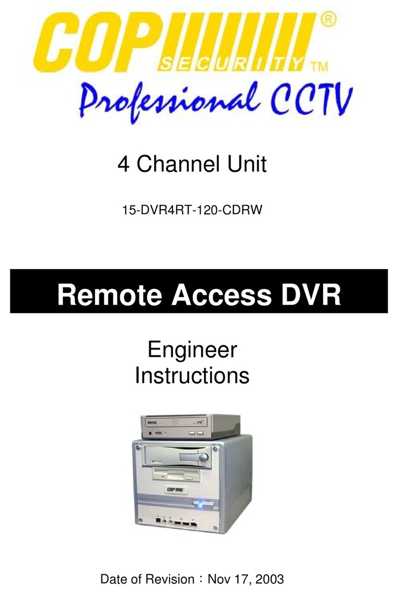
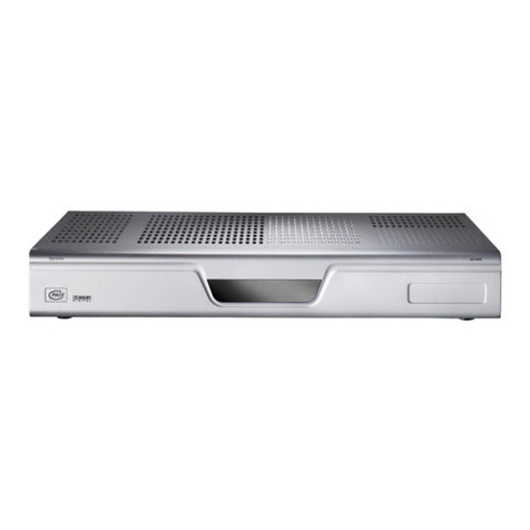
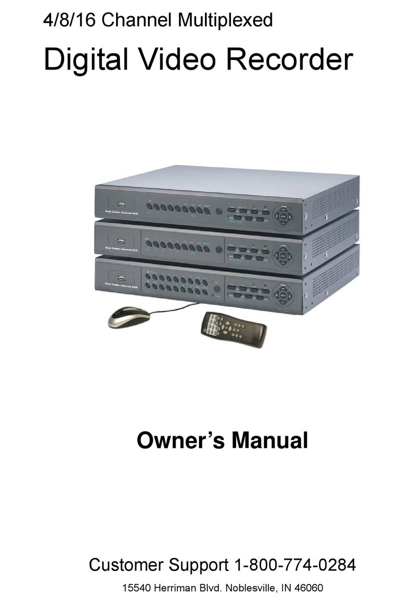
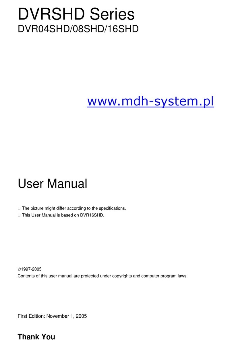
COP Security 15-VT04-CDRW User manual

◄Triplex DVR►
1
User's Manual
Triplex Real Time Stand Alone DVR
15-VT04-CDRW
15-VT08-CDRW
15-VT16-CDRW
[ 4 / 8 / 16 Channel DVR ]

◄Triplex DVR►
2
CAUTION
TO REDUCE THE RISK OF ELECTRICAL SHOCK, DO NOT OPEN COVERS.
NO USER SERVICEABLE PARTS INSIDE. REFER SERVICING TO QUALIFIED S
NO USER SERVICEABLE PARTS INSIDE. REFER SERVICING TO QUALIFIED SERVICE PERSONNEL.
ERVICE PERSONNEL.
Note
Note
PLEASE READ THIS MANUAL THOROUGHLY FOR EFFECTIVE AND SAFE USAGE
OF THE DEVICE.
OF THE DEVICE.
This equipment had been tested and found to comply with the limits for a CLASS A digi
tal device, pursuant to Part 15 of FCC Rules. These limits are designed to provide reas
onable protection against harmful interference when the equipment is operated in a
commercial environment.
Please beware of the following precautions before installing the DVR.
•Avoid any place with moisture, dust, or soot.
•Avoid any place with direct sunlight or heating appliances.
•Keep the product away from electric shock or magnetic substances.
•Avoid high or low temperature.
(Recommended operation temperature is between 0°C ~ 40°C).
•Do not place any conductive material through the ventilation.
•Turn off the system before installation.
•Ensure enough space for cable connections.
•Place the system on a solid surface with sufficient air ventilation.
Avoid any surface that vibrates.
•Placing the system near electronic devices such as radio or TV may cause breakdown
to the product.
•Do not disassemble the product without an assistance from the manufacturer.
•Do not place any heavy object on the system.
◄Triplex DVR►
3
CHAPTER 1. KEY FEATURES
CHAPTER 2. PACKING DRTAILS
CHAPTER 3. NAMES AND FUNCTIONS
3.1 FRONT PANEL
3.2 REAR PANEL
CHAPETR 4. INSTALLATION
4.1 TOTAL CONNECTION DIAGRAM
4.2 INDIVIDUAL CONNECTION
4.2.1 POWER
4.2.2 CAMERA
4.2.3 MONITOR
4.2.5 AUDIO
4.2.6 USB
CHAPTER 5. OPERATION
5.1 FACTORY DEFAULT
5.2 FRONT PANEL CONTROL
FUNCTION
5.2.1 MULTI DISPLAY
5.2.2 PIP DISPLAY
5.2.3 AUTO DISPLAY
5.2.4 TRIPLEX DISPLAY
5.2.5 DVR INFORMATION
5.2.6 RECORD
5.2.7 SEARCH & PLAYBACK
5.3 REMOTE CONTROLLER
5.3.1 REMOTE CONTROL
FUNCTION
5.3.2 MUTE
Contents
6~7
8
9~10
13
14
15
16
17
18
18
19
19
20
9
21
22~23
24
25
26~27
28
11~12
28
13
14
14
29

◄Triplex DVR►
4
5.3.3 DIGITAL ZOOM
5.3.4 PANORAMA
5.3.5 PTZ CONTROL
5.3.6 BACKUP
CHAPTER 6. SETUP MENU
6.1 LANGUAGE
6.2 SYSTEM SETUP
6.2.1 HDD SETUP
6.2.2 PASSWORD SETUP
6.2.3 CHANNEL NAME SETUP
6.2.4 DATE/TIME SETUP
6.2.5 BEEP & PTZ SETUP
6.2.6 SYSTEM RESET
6.3 DISPLAY SETUP
6.3.1 BLANK CHANNEL SETUP
6.3.2 PIP CHANNEL SETUP
6.3.3 ADJUST CHANNEL SETUP
6.3.4 VIDEO SIGNAL TYPE
6.3.5 SEQUENCE
6.3.6 BOUNDARY COLOR
6.3.7 BACKGROUND COLOR
6.4 EVENT SETUP
6.4.1 RECORD TIME
6.4.2 SENSOR IN
6.4.3 EVENT ACTION
6.4.4 MOTION SETUP
6.5 RECORD SETUP
6.5.1 RECORD RES
6.5.2 RECORD SPEED
6.5.3 RECORD QUALITY
6.5.4 PB SPEED
6.5.5 CHANNEL ENABLE
6.5.6 AUDIO SETUP
6.5.7 SCHEDULE SETUP
Contents
31
32~33
34~35
37
38
40
43
43
44
45
47
46
46
47
48
48
48
36
49
50
51
51
51
51
37
30
42
51
36
39
41
52
52
52

◄Triplex DVR►
5
Contents
54
58
59
53
56~57
54~55
60
60
60
60
61~62
63~64
6.6 NETWORK SETUP
CHAPTER 7. EXTERNAL TERMINAL
INFORMATION
7.1 RS-232
7.2 ALARM IN/OUT & RS-485
7.4 ETHERNET & USB
CHAPTER 8. SPECIFICATIONS
CHAPTER 10. NETWORK CLIENT
VIEWER MANUAL
10.1 SYSTEM REQUIREMENT
10.2 NETWORK ENVIRONMENT
10.3 NETWORK VIEWER
INSTALLATION
10.4 NAMES & FUNCTIONS
10.5 OPERATION
10.5.1 LIVE VIEW MODE
10.5.2 PLAYBACK MODE
10.5.4 FILE PLAY MODE
10.5.5 CD PLAY MODE
CHAPTER 11. Q & A
63
65
67
66
68~69

◄Triplex DVR►
6
CHAPTER 1. KEY FEATURES
Operation
•Display, Playback, Recording, Network and transmission simultaneously
•Real time single or multi-screen display
•Triplex display (8ch Live & 8ch playback display)
•Pan& Tilt, 2X digital zoom and 3xPIP display
•Easy operation by IR remote controller
•Hidden camera option (covert)
•User-friendly setup menu and operation
Playback
•Multi-screen playback (Full, Quad, 6/ 8/ 9/ 16split)
•Search by date / time list, event list and data / time
•Select playback speed mode
Recording
•Set the recording quality from 1 to 6
•Frame rate can be set by user 1-100 FPS
•Manual, schedule and event (motion, alarm) recording
•Select of the recording Resolution High / Low
•1 channel audio recording

◄Triplex DVR►
7
Audio
•1 channel audio recording in real time
•Audio channel select link for each camera channel
BACKUP
•CD-RW backup
•USB Backup (Still image backup) (Only available for 16CH DVR)
General
•Built-in hardware Watchdog
•Automatic time adjustment through Network
•VGA output for PC monitor (Optional)
•S-Video output
•Alarm In/Out, RS-485, RS-232 Connections
•Loop-through connections
•Support of multiple Languages

◄Triplex DVR►
8
CHAPTER 2. PACKING DETAILS
4. Remote controller
3. User’s Manual
1. DVR
2. Network Viewer Program CD
7. Power Cord
6. DC Adaptor
8. HDD Screws
5. Battery
CONTENTS
1. DVR System
2. Network Viewer Program CD
3. User’s Manual
4. Remote controller
6. DC Adaptor
7. Power Cord
5. Battery
8. HDD Screws

◄Triplex DVR►
9
3.1 FRONT PANEL
1. 1 to 16 Channel Selection / Direction
• To select a channel to be viewed as full-size screen during live display or playback.
• To navigate, press Up(1) / Down(2) / Left(3) / Right(4).
2 ~ 5. LED Signs
• There are four LED signs that indicate current status.
2. POWER : DVR power status
3. NET : ON means connection status via network.
If someone accesses the DVR via network, LED light turns on.
4. PLAY : ON means the DVR is in search mode of playback.
5. REC : ON means the DVR is recording.
6. Remote Controller Sensor
7. MODE
• It converts to live display mode directly.
• To surf various live display modes like 16CH, 13CH, 9CH, 8CH and 6CH display
by pressing the button repeatedly.
8. PIP
• To convert to PIP mode (Picture in Picture ).
• To surf various PIP modes like 1PIP, 2PIPs and 3PIPs by pressing the button repeatedly.
9. SEQ
• To convert to auto switch mode.
• If you press AUTO on the front panel, channels will be automatically switched as follows.
- Ch1 -> Ch2 -> Ch3 ->….-> Ch14 -> Ch15 -> Ch16 -> 16Ch in CIF -> Ch1 -> Ch2 …
keeping this order until you press Auto button again to release the function.
CHAPTER 3. NAMES AND FUNCTIONS
1
2
3
4
5
6
97
8
10
11
17 20
1918
13 14 15
16
12

◄Triplex DVR►
10
10. TRI (TRIPLEX)
• To convert to triplex function like 8 channel live display and 8 channel playback in the screen
simultaneously.
• Press the button first, you will have CH1 ~ CH 8 live displays and playbacks and press it again,
you will do other channels like CH9 ~ CH16 live displays and playbacks.
-When you press the button in live display mode, you will see 8 channel live displays and
8 channel playbacks with no video.
-When you press the button in playback mode, you will see 8 channel live displays and
8 channel playbacks that have selected.
11. INFO (INFORMATION)
• To show system information of DVR
12. CD-Burner
• To burn CD for data back-up
13. REWIND ()
• Speed X5, X10 and X20
14. PLAY () / PAUSE (II)
• To play and pause the recorded videos
15. Faster Forward ()
• Speed X5, X10 and X20
16. STOP (■)
17. RECORD (●)
• To start and stop recording.
18. SEARCH
• To access recordings from HDD
19. ENTER
• To enter a selection
20. MENU
• To access System Setup Menu.

◄Triplex DVR►
11
3.2 REAR PANEL
1 2 4 12
[ 16CH DVR ]
763 5 9 10811
[ 8CH DVR ]
[ 4CH DVR ]

◄Triplex DVR►
12
1. Cooling Fan
2. Power Switch
3. AC Power Inlet
4. 16 BNC connectors for camera input
5. 16 BNC connectors for monitor output
These are mainly for monitors. And also you can use these for VCR recorder backup.
6. Audio In / Out Port
7. USB Port (16CH Only)
8. RS-232 Port (9 Pin D-Sub Connector)
• It is mainly for download port for system upgrade.
9. Alarm In / Out and RS-485 Port (25 Pin D-Sub Connector)
• It is to communicate with external sensors, alarm and PTZ camera to control.
10. S-Video Output
11. LAN Terminal
• It is to connect to LAN or Internet.
12. BNC connectors for monitor output
• These are mainly for monitors. And also you can use these for VCR recorder backup.

◄Triplex DVR►
13
CHAPTER 4. INSTALLATION
4.1 TOTAL CONNECTION DIAGRAM

◄Triplex DVR►
14
4.2 INDIVIDUAL CONNECTION
4.2.1 POWER
4.2.2 CAMERA
16 Cameras
…………………………...............
* Connect the DC adaptor provided in the package.
* And then turn on the power switch.
* Connect a female BNC connector of each camera to a male BNC connector, ”CAMERA IN” ports.

◄Triplex DVR►
15
4.2.3 MONITOR
* Connect the female BNC for monitor output.
* Connect the male DIN socket for S-VIDEO monitor output. [ S-VIDEO ]
[ Main Monitor ]

◄Triplex DVR►
16
4.2.5 AUDIO
Audio
Monitor
Amplified
Speaker
* Audio Input
- AUDIO IN : Connect the RCA Line Jack of the relevant equipment (for example, a camera with a
built-in microphone ) to the AUDIO IN port.
* Audio Output
- AUDIO OUT : Connect the RCA Line output to a monitor with a built-in speaker.
Note
Note
This DVR can be connected only with a line audio and does not support a microphone for audio
input.
To record audio, AUDIO function should be enable in the AUDIO setup of main menu.
As the audio is linked to a camera, it is required that linked camera should be viewed on the
Screen during playback in order to hear the recorded audio.

◄Triplex DVR►
17
4.2.6 USB (USB 2.0 port)
* The USB port is provided to connect USB memory stick for video still image copying.
* This function is available only for 16CH DVR.
* Installation Process
1) Turn off the power of DVR.
2) Connect USB memory stick to DVR.
3) Turn the power of DVR on.

◄Triplex DVR►
18
CHAPTER 5. OPERATION
5.1 FACTORY DEFAULT
5.1.1 Language : English
5.1.2 System Setup
- Overwrite : ON
- Password : OFF (when switched on default password is 0000)
- Channel Name Setup : Live & PB - ON
- Date / Time Setup : Live & PB - ON
- Rec. Beep : ON
- HDD Fail : ON
- Blank Channel Setup : OFF
- PIP Channel Setup : Main - CH 1 / SUB 1 – CH 2 / SUB 2 – CH 3 / SUB 3 – CH 4
- Adjust Channel Setup : CON/ HUE/ BRI/ COL – 50
- Boundary : white
- Background : Blue
- Motion Action : OFF
- Record Setup : Resolution – Normal / Speed – 100 F/S
- Network Setup
NET ID : 12345678
PASSWD :00000000
PORT : 5000

◄Triplex DVR►
19
5.2 FRONT PANEL CONTROL FUNCTION
5.2.1 MULTI DISPLAY
Users can set “MULTI DISPLAY” functions in any mode.
It converts to 16 channel live display on the screen as below by pressing Mode button.
* To convert to live display, press MODE button in any mode.
You can surf 13 CH / 9 CH / 8 CH / 6 CH display by pressing MULTU button repeatedly.
[ 13 CH display Mode] [ 9 CH display Mode]
[ 6 CH display Mode]
[ 8 CH display Mode]

◄Triplex DVR►
20
You can select PIP ( Picture In Picture ) options by pressing PIP button repeatedly. PIP mode offers a
convenient way of monitoring multiple channels while focusing more attention on a particular channel. It
has a main video channel view and up to 3 small video channel views on the screen.
You can surf 1 PIP/ 2 PIPs/ 3 PIPs mode with 4 positions by pressing PIP button repeatedly.
To release this mode, press another function button on the front panel.
[ 1PIP ] [ 2 PIPs ] [ 3 PIPs ]
5.2.2 PIP DISPLAY
This manual suits for next models
2
Table of contents
Other COP Security DVR manuals

COP Security
COP Security 15-WP16-USB User manual

COP Security
COP Security inspire black 960h User manual

COP Security
COP Security Inspire Blue V2 User manual

COP Security
COP Security 15-DVR4RT-120-CDRW Quick start guide

COP Security
COP Security 15-DVR16SAE-LAN User manual

COP Security
COP Security INSPIRE User manual

COP Security
COP Security XT Series User manual

COP Security
COP Security INSPIRE WHITE series User manual

COP Security
COP Security DVR04SHD User manual

COP Security
COP Security 325HR User manual