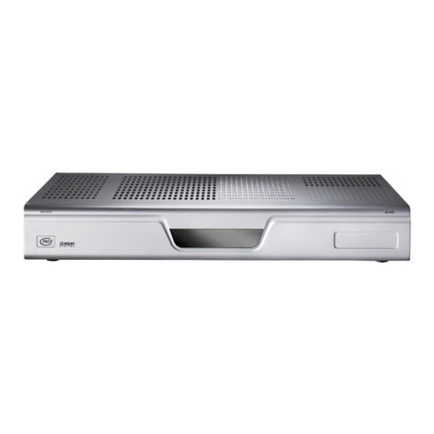
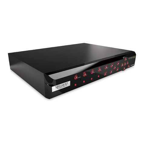
COP Security XT Series User manual

4 Channel DVR manual
Rev 2.2 - September 2006
XT Series

2
CAUTION
RISK OF ELECTRONIC SHOCK
DO NOT OPEN
CAUTION: TO REDUCE THE RISK OF ELECTRONIC SHOCK,
DO NOT REMOVE COVER (OR BACK). NO USER
SERVICEABLE PARTS INSIDE. REFER SERVICING TO
QUALIFIED SERVICE PERSONNEL.
Graphic Symbol Explanation
This symbol is intended to alert the user to the presence
of important operating and maintenance (servicing)
instructions in the literature accompanying the product.
This symbol is intended to alert the user to the presence of
uninsulated “dangerous voltage”within the product’s
enclosure that may be of sufficient magnitude to constitute a
risk of electric shock to persons.

3
IMPORTANT SAFEGUARDS AND WARNINGS
1. Read Owner’s Manual
All the safety and operating instructions should be
read before this product is operated.
2. Follow Instructions
All operating and use instructions should be followed.
3. Power Sources
This product should be operated only from the type
of power source indicated on the marking
label. If you are not sure of the type of power
supply to your home or business, consult
your product dealer or local power company.
4. Power Cord Protection
Power-supply cords should be routed so that they
are not likely to be walked on or pinched by
items placed upon or against them, paying
particular attention to cords at plugs,
convenience receptacles, and the point
where they exit from the product.
5. Cleaning
Unplug this product from the wall outlet before
cleaning. Do not use liquid cleaners or
aerosol cleaners. Use a damp cloth for
cleaning.
6. Water and Moisture
Do not use this product near water.
7. Attachments
Do not use attachments not recommended by this
product manufacturer as they may cause
hazards.
8. Accessories
Do not place this product on an unstable cart, stand,
tripod, bracket, or table. The product may
fall, causing serious injury to a child or an
adult, and serious damage to the product.
Use only with a cart, stand, tripod, bracket, or
table recommended by the manufacturer, or
solid with the product. Any mounting of the
product should follow the manufacturer’s
instructions and should use a mounting
accessory recommended by the
manufacturer. The product and cart
combination should be moved carefully.
Quick stop, excessive force, and uneven
surfaces may cause the product and cart
combination to overturn.
9. Ventilation
Slots and openings in the cabinet are provided for
ventilation and to ensure reliable operation of
the product and to protect it from
overheating, and these openings must not be
blocked or covered. This product should not
be placed near or over a radiator or heat
register. This product should not be placed in
a built-in installation such as a bookcase or
rack unless proper ventilation is provided or
the manufacturer’s instructions have been
adhered to.
10. Lightning
For added protection for this product during a
lightning storm, or when it is left unattended
and unused for long periods of time, unplug it
from the wall outlet and disconnect the cable
system. This will prevent damage to the
product due to lightning and power-line
surges.
11. Overloading
Do not overload wall outlets and extension cords as
this can result in a risk of fire or electric
shock.
12. Object and Liquid Entry
Never push objects of any kind into this product
through openings as they may touch
dangerous voltage points or short-out parts
that could result in a fire or electric shock.
Never spill liquid of any kind on the product.
13. Servicing
Do not attempt to service this product yourself as
opening or removing covers may expose you
to dangerous voltage or other hazards. Refer
all servicing to qualified service personnel.
14. Damage Requiring Service
Unplug this product from the wall outlet and refer
servicing to qualified service personnel under
the following conditions.
▶When the power-supply cord or plug is damaged.
▶If liquid has been spilled, or objects have fallen
into the product.
▶If the product has been exposed to rain or water.
▶If the product dose not operate normally by
following the operating instruction. Adjust
only those controls that are covered by the
operating instructions, as an improper
adjustment of other controls may result in
damage and will often require extensive work
by a qualified technician to restore the
product to its normal operation.
▶If the product has been dropped or the cabinet has
been damaged.
▶When the product exhibits a distinct change in
performance this indicates a need for
service.
15. Replacement Parts
When replacement parts are required, be sure the
service technician has used replacement
parts specified by the manufacturer or have
the same characteristics as the original part.
Unauthorized substitutions may result in fire,
electric shock or other hazards.
16. Safety Check
Upon completion of any service or repairs to this
product, asks the service technician to
perform safety checks to determine that the
product is in proper operating condition.
IMPORTANT SAFEGUARDS AND WARNINGS
4
CONTENTS
CONTENTS
CONTENTS 4
1. Buttons and Connections 5
1-2 REAR PANEL 6
3-5 SETUP – NETWORK 31
3-6 SETUP – SENSOR/ALARM 37
2-1 REMOTE CONTROLLER FUNCTIONS 7
2-4 CURRENT STATUS & TIME SET-UP 9
3. SETUP 10
13. SEQ(Sequence) 51
14. SCREEN SPLIT 51
15. BACKUP VIEWER – CD
Playback 52
16-4 Search Mode – Remote Playback 68
16. CMS – Remote Monitoring
Software 54
16-1 Display Mode 54
16-2 Setup Mode 58
16-3 Remote Setup Mode 66
1-1 FRONT PANEL FUNCTIONS 5
2. Quick Start – Power On 8
3-2 SETUP – LIVE 16
3-3 SETUP - REC 22
3-4 SETUP – STORAGE 30
3-6 SETUP – AUDIO 41
4. SEARCH 42
4-1 TIME SEARCH 42
4-2 EVENT SEARCH 43
4-3 FILE SEARCH 44
5. STATUS 45
12. POP(Picture on Picture) 50
6. AUDIO 45
7. BACKUP 46
8. PTZF(Pan/Tilt/Zoom/Focus) 48
9. LOG 49
10. SPOT 50
11. PIP(Picture in Picture) 50
2-1 POWER ON 8
2-2 PASSWORD 8
3-1 SETUP – SYSTEM 11

5
1. Buttons & Connections
1) Number Buttons – Dual Function Buttons
Provide Menu Data entry and Alternative Functions:
See 3), 8), 7), 14) & 16) Below.
2) Manual Record Button
Starts & Stops Continuous Recording.
(Not required for Schedule or Event Recording)
3) Function Button – Displays the User Function Menu
Status, Audio, Backup, P/T/Z, SEQ, Log list
4) Menu Button
Displays the Main Menu, after correct password entry,
and Exits the current Menu.
5) Cursor Buttons
Provide navigation through menus. Also provides Pan
Tilt & Zoom operation of PTZ cameras.
6) Enter Button
Enters Sub-Menus and performs setup changes.
7) Log Button
Displays the Log Menu, and Exits the Log Menu.
8) Search Button
Displays Playback Search Menu
9) Fast Rewind Button
Plays backward upto 128x normal speed.
Reverse frame by frame playback when play paused.
10) Play/Pause Button
Pauses and re-starts playback
11) Stop Button
Stops playback and reverts display to Live mode
12) Fast Forward Button
Plays forward upto 128x normal speed.
Advance frame by frame playback when play paused.
14) PIP Button Shows “Picture In Picture” on Main Monitor
16) Sequence Button
Shows Sequence of Single or Quad Images
17) Single Channel Button
When pressed repeatedly will scroll from 1 thru 4
18) Quad Channel Button
21) Led Condition Indicators
Indicates present system status information
(PWR: System On/Off, REC: Record On/Off,
BAK: Backup On/Off )
22) Infra-Red Remote Control Receiver
23) USB 2.0 Socket
For backup / archive of recordings to USB device.
1-1 FRONT PANEL – 4 Channel
1. USAGE OF FUNCTION KEYS
1
2
3
4
5
6
78
910 11 12
14 16
17 18
21
22
23

6
1-2 REAR PANEL
1
2
34
6
7
8
911
12
13
1. USAGE OF FUNCTION KEYS
1) Video Input
Composite video input – 16 BNC Female Sockets
2) Loop-Through Output Port
3) Audio Inputs
Four Audio Input Phono / RCA Sockets
4) Alarm Input, Alarm Output and Telemetry Connections.
“No-Tools” connectors for Alarm and Telemetry cables.
6) Main Monitor Output – 2 x BNC
Composite Video Output – Two BNC Female Socket.
7) Main Monitor Output - S-VIDEO
S-Video Output – One 5-Pin DIN Socket
8) Audio Output
One Audio Output Phono / RCA Socket
9) Ethernet Port:
RJ45 Socket for connection to a LAN Network Device.
11) Main Monitor Output - VGA
VGA Video Output – One 15-Pin D-Type Socket.
12) RS-232
Connection Port for Engineering Use Only.
13) Power Switch
System Power On/Off Switch.

7
1) Number Buttons
Provides channel selection and Menu Data entry
2) Status Button
Shows the current status of DVR system
3) Audio Button
Displays Audio Options Menu
4) Backup Button
Displays Backup Options Menu
5) P/T Button
Enables Pan & Tilt Functions
6) Z/F Button
Enables Zoom & Focus Functions
7) REC. Button
Records images
8) Manual Record Button
Starts & Stops Continuous Recording
(Not required for Schedule or Event Recording)
9) Menu Button
Displays the Main Menu, after correct password entry
Exits the current Menu
10) Cursor Buttons
Provide navigation through menus & PTZ Operation
11) Enter Button
Enters Sub-Menus and executes setup changes
12) Search Button
Displays (& Exits) Playback Search Menu
13) Log Button
Displays (& Exits) the Log Menu.
14) Fast Rewind Button
Plays backward upto 128x normal speed
Reverse frame by frame playback when play paused
15) Play/Pause Button
Pauses and re-starts playback
16) Fast Forward Button
Plays forward upto 128x normal speed
Advance frame by frame playback when play paused
17) Stop Button
Stops playback and reverts display to Live mode
18) SPOT button
Displays Spot monitor setup menu
19) PIP Button Shows “Picture In Picture” on Main Monitor
20) POP Button Shows “Picture On Picture” on Main Monitor
21) Sequence Button
Shows Sequence of Single or Quad Images
22) Single Channel Button
23) Quad Channel Button
24) Nine Channel Button
25) Sixteen Channel Button
1
2
3
4
5
6
8
7
9
1011
12
13
14 15 16 17
18 19 20 21
22 23 24 25
1.3 Remote controller
1. USAGE OF FUNCTION KEYS
10
10
10

8
2. QUICK START
1) Connect at least one Monitor to either the VGA, Composite or S-Video Main Monitor output.
2) Connect at least 1 camera to the camera inputs for the DVR to detect a PAL signal.
1) Connect mains power cable to the External PSU and the 12 volt power plug to the DVR.
2) Turn on the power switch.
1) System will start boot sequence (This will take approx. 30 seconds to complete)
2) User will be asked to input a password after boot sequence is completed. (Default password is 0000.)
3) Refer to 3-1-1 (page 11) for instructions to change the password.
1) Live images, date and time will appear on the screen.
2) [A:00%]/[B:00% or NONE] will be displayed in the bottom of left corner to show HDD presence and usage.
NOTE: In some rare instances the DVR may automatically select NTSC as the display type.
Main Symptom: Camera Images appear to “Stutter” (Almost “Time Lapsed” in appearance).
To change the display type back to PAL, disconnect ALL cameras and re-start the DVR.
Once re-started, re-connect the cameras.
The camera images should now be smooth and “Real Time in appearance.
Please call our Technical Support Team for assistance should you need further advice.
2-3. First Display
2-2. Password
2-1. POWER ON
LOADING . . . ENTER PASSWORD
: _ _ _ _
2. START SYSTEM

9
[STATUS]
S/W VERSION : VO.9.0-ft-16 (07/11/05 20:40)
[HDD] A: 75G ( 10.57%) B: NONE
C: CD-RW D: NONE
NETWORK : STATIC 192 . 168 . 1 . 200
MAC : 00 . 0E . B5 . 00 . 05 . EA
DDNS : DDNS OFF
[REC] SIZE : 720X288
CH RT QUAL CH RT QUAL CH RT QUAL CH RT QUAL
1 6 NORM 5 6 NORM 9 6 NORM 13 6 NORM
2 6 NORM 6 6 NORM 10 6 NORM 14 6 NORM
3 6 NORM 7 6 NORM 11 6 NORM 15 6 NORM
4 6 NORM 8 6 NORM 12 6 NORM 16 6 NORM
S/W VER DVR program version ( the date of program
update)
Drive Data HDD or CDRW
HDD HDD size (and current usage)
NETWORK Fixed or dynamic IP address
MAC DVR Network MAC Address
DDNS DDNS service status for dynamic IP user.
[REC]
SIZE Recording image resolution (global setting)
CH Individual Camera Number
RT Recording frame rate for each camera.
BEST Best
quality
HIGH High
quality
Normal
quality
Basic
quality
BASC
NORM
QUAL Recording image
quality.
2-4 Current STATUS & Time Setup
2. QUICK START
1) Press the Function Menu and select “Status” from the Menu.
Or
Press the “Status” Button on the IR Remote.
2) The current Status of the DVR will be displayed as below.
3) Settings cannot be changed from here
Exit the Status Display
(Press Status or Menu button)
Then Press the Record Button.
The DVR will record continuously
at the quality and frame rate as shown.
4) If Time & Date settings need adjustment, the DVR Menu has to be accessed.
Press the Menu Button. Then enter the Password (default 0000)
Use Cursor and Enter Buttons to enter the <SYSTEM> sub-menu
Use Cursor and Enter Buttons to enter the <TIME SETUP> sub-menu.
Adjust the Time & Date using the Number and Cursor buttons – Press ENTER after adjustment
At the warning screen, press ENTER if you are sure of the new Time & Date.
Press the Menu Button to exit each Menu.
For full instructions to carry out Time & Date changes, see Page 12.
5) The DVR will now be recording at the settings that were displayed in the Status Display Screen.

10
3. SETUP
3. SETUP
1) To change the DVR Setup, the Setup Menu has to be accessed.
2) Press the [MENU] button and type in the password to enter the Setup Menu.
(Default PASSWORD : 0000)
From this Sub-menu all the Parameters for the DVR can be adjusted, and maintenance operations
such as Formatting of the HDD(s) can be performed.
Setup Menus Navigation.
To navigate the Setup Menu and the Sub-Menus, the cursor (▲)(▼)(◀)(▶) buttons are
used in conjunction with the [ENTER] button (to enter a Sub-Menu) and the [MENU]
button (to exit any Sub-Menus).
Within some Sub-Menus the cursor (▲)(▼)(◀)(▶) buttons can be used to change
parameters, along with the Number Buttons.
NOTE: If parameters are changed in this way,
the [ENTER] button is used to save these changes.
ENTER ADMIN
PASSWORD
: _ _ _ _
[SETUP]
-<SYSTEM>
-LIVE
-REC
-STORAGE
-NETWORK
- SENSOR/ALARM
- AUDIO

11
1) To change the System Setup, the System Sub-Menu has to be accessed.
2) Select [SYSTEM] using cursor (▲)(▼) buttons and press [ENTER] button to enter the Sub-Menu.
3-1-1. SETUP-SYSTEM-ADMIN PASSWORD (& USER PASSWORD)
This Sub-Menu is how to change the Passwords.
(Note: These Passwords are Enabled / Disabled in the [PASSWORD CHECK] Sub-Menu, Page 14)
1) Select [ADMIN PASSWORD] by using cursor (▲)(▼)
buttons and press [ENTER] button to enter the
Sub-Menu. (Default PASSWORDS : 0000)
3) Enter the new password when prompted and re-enter the password to confirm your new password.
Change the USER PASSWORD in the same way as the above from that Sub-Menu.
- ADMIN PASSWORD : Used for system start and setup changes
- USER PASSWORD : Used only when the system starts after power-up.
3-1. SETUP – SYSTEM
[SETUP-SYSTEM-ADMIN]
ENTER NEW ADMIN
PASSWORD
: _ _ _ _
[SETUP-SYSTEM-ADMIN]
CONFIRM NEW ADMIN
PASSWORD
: _ _ _ _
3. SETUP
[SETUP]
-<SYSTEM>
-LIVE
-REC
-STORAGE
-NETWORK
- SENSOR/ALARM
- AUDIO
[SETUP-SYSTEM]
-<ADMIN PASSWORD>
- USER PASSWORD
- PASSWORD CHECK
- TIME SETUP
- TIME FORMAT
- TIME OSD FORMAT
- TIME STAMP FORMAT
- CURRENT STATUS VIEW
- VGA FREQUENCY CHANGE
- SOFTWARE UPDATE
- DEFAULT SETUP
[SETUP-SYSTEM]
-<ADMIN PASSWORD>
- USER PASSWORD
- PASSWORD CHECK
- TIME SETUP
- TIME FORMAT
- TIME OSD FORMAT
- TIME STAMP FORMAT
- CURRENT STATUS VIEW
- VGA FREQUENCY CHANGE
- SOFTWARE UPDATE
- DEFAULT SETUP

12
3-1-2. SETUP-SYSTEM-PASSWORD CHECK
This section enables (or disables) the Admin & User Password checks.
1) Select [PASSWORD CHECK] using cursor (▲)(▼) buttons and press [ENTER] button.
2) Select [ON] (or [OFF]) next to [ADMIN] and press the [ENTER] button.
3) Use the Cursor (▲)(▼) buttons to highlight your choice then press the [ENTER] button to select.
★Note : If User Password Check is on, If DVR has been turned off, this provides a warning.
★Note : If Admin Password Check is off, anybody can access the System Setup
4) Repeat 2) & 3) for [USER] Password Check if required.
3-1-3. SETUP-SYSTEM-TIME SETUP
1) Select [TIME SETUP] by using (▲)(▼) buttons and press [ENTER] button to enter the sub-menu.
2) Year/Month/Day/Time can be changed by using the number buttons.
3) Press [ENTER] button to save the changes.
4) A warning message appears after any change to the Time or Date. Press [ENTER] button to accept.
5) If the time or date has been adjusted to an earlier time, any previous recordings with an overlapping
time will be deleted, as shown in the diagram above.
[SETUP-SYSTEM-PASSWORD
CHECK]
ADMIN : < ON >
USER : < ON > CHECK
PASSWORD
-OFF
-ON
-OFF
[SETUP-SYSTEM-TIME
SETUP]
YEAR : 2005
MONTH : 06
DAY : 20
TIME : 12 : 30
[WARNING!!!]
TIME WILL BE CHANGED
THE FILES AFTER CHANGED
TIME
WILL BE DELETE
ARE YOU SURE?
[ENTER] -> YES [MENU] ->
NO
3. SETUP
[SETUP-SYSTEM]
-<ADMIN PASSWORD>
- USER PASSWORD
- PASSWORD CHECK
- TIME SETUP
- TIME FORMAT
- TIME OSD FORMAT
- TIME STAMP FORMAT
- CURRENT STATUS VIEW
- VGA FREQUENCY CHANGE
- SOFTWARE UPDATE
- DEFAULT SETUP
[SETUP-SYSTEM]
-<ADMIN PASSWORD>
- USER PASSWORD
- PASSWORD CHECK
- TIME SETUP
- TIME FORMAT
- TIME OSD FORMAT
- TIME STAMP FORMAT
- CURRENT STATUS VIEW
- VGA FREQUENCY CHANGE
- SOFTWARE UPDATE
- DEFAULT SETUP

13
3-1-4. SETUP-SYSTEM-TIME FORMAT
In this Sub-Menu the Date Display format can be changed. (Shown in the table below)
1) Select the desired display format by using (▲)(▼) button and press [ENTER] button to select.
2) Press [MENU] after the change is completed.
3-1-5. SETUP-SYSTEM-TIME OSD FORMAT
In this Sub-Menu the position and colour format of the Time / Date display can be changed.
1) From the [TIME FORMAT] sub-menu, Select a display format by using (▲)(▼) button and press the
[ENTER] button to apply.
3) Some Alternative display formats are shown below.
4) Press the [MENU] button after the setup is completed to exit the Sub and Main Menus.
[SETUP-SYSTEM-TIME FORMAT]
- YY / MM / DD TIME FORMAT
- YY / MM / DD
- DD / MM / YY
- MM/DD/YY
- DD/MM/YY
EX. CURRENT DATE 2005- 2- 30
FORMAT DISPLAY
YY/MM/DD 2005/12/30
30/12/2005
12/30/2005
DD/MM/YY
MM/DD/YY
[SETUP-SYSTEM-TIME OSD FORMAT]
- <TOP-WHITE> TIME OSD FORMAT
-TOP-WHITE
-TOP-BLACK
- BOTTOM-WHITE
- BOTTOM-BLACK
-OFF
- BOTTOM-WHITE
2005/06/20 12:30:05
TOP-WHITE
BOTTOM-BLACK
TOP-BLACK
BOTTOM-WHITE
OFF
2005/06/20 12:30:05 2005/06/20 12:30:05
2005/06/20 12:30:05
3. SETUP
[SETUP-SYSTEM]
-<ADMIN PASSWORD>
- USER PASSWORD
- PASSWORD CHECK
- TIME SETUP
- TIME FORMAT
- TIME OSD FORMAT
- TIME STAMP FORMAT
- CURRENT STATUS VIEW
- VGA FREQUENCY CHANGE
- SOFTWARE UPDATE
- DEFAULT SETUP
[SETUP-SYSTEM]
-<ADMIN PASSWORD>
- USER PASSWORD
- PASSWORD CHECK
- TIME SETUP
- TIME FORMAT
- TIME OSD FORMAT
- TIME STAMP FORMAT
- CURRENT STATUS VIEW
- VGA FREQUENCY CHANGE
- SOFTWARE UPDATE
- DEFAULT SETUP

14
3-1-6. SETUP-SYSTEM-TIME STAMP FORMAT
1) The position and colour of the Time & Date displayed during playback can be changed from the [TIME
STAMP FORMAT] Sub-Menu.
2) Select a display format by using (▲)(▼) button and press the [ENTER] button to apply.
3) Some Alternative displays are shown below.
4) Press the [ENTER] button to accept the choice.
3-1-7. SETUP-SYSTEM-CURRENT STATUS VIEW
This Sub-Menu allows the System Information to be displayed, or hidden, on the Main Monitor Screen.
1). From the [CURRENT STATUS VIEW] sub-menu, Select YES or NO by using (▲)(▼) button and press
the [ENTER] button to apply. (This will not affect the Time & Date Display settings)
2) Press [MENU] after the change is completed.
[SETUP-SYSTEM-TIME STAMP FORMAT]
- <TOP-WHITE> TIME STAMP FORMAT
-TOP-WHITE
-TOP-BLACK
- BOTTOM-WHITE
- BOTTOM-BLACK
-OFF
- BOTTOM-WHITE
2005/06/20 12:30:05
TOP-WHITE
BOTTOM-BLACK
TOP-BLACK
BOTTOM-WHITE
OFF
2005/06/20 12:30:05 2005/06/20 12:30:05
2005/06/20 12:30:05
3. SETUP
[SETUP-SYSTEM]
-<ADMIN PASSWORD>
- USER PASSWORD
- PASSWORD CHECK
- TIME SETUP
- TIME FORMAT
- TIME OSD FORMAT
- TIME STAMP FORMAT
- CURRENT STATUS VIEW
- VGA FREQUENCY CHANGE
- SOFTWARE UPDATE
- DEFAULT SETUP
[SETUP-SYSTEM]
-<ADMIN PASSWORD>
- USER PASSWORD
- PASSWORD CHECK
- TIME SETUP
- TIME FORMAT
- TIME OSD FORMAT
- TIME STAMP FORMAT
- CURRENT STATUS VIEW
- VGA FREQUENCY CHANGE
- SOFTWARE UPDATE
- DEFAULT SETUP
[SETUP-SYSTEM-CURRENT STATUS VIEW]
> ON CURRENT STATUS VIEW
-OFF
-ON
-OFF

15
3-1-8. SETUP-SYSTEM-VGA FREQUENCY CHANGE
This Sub-Menu allows the vertical scanning frequency of the VGA output to be adjusted for the type of
VGA Monitor being used. (Most TFT screens will need this to be adjusted to 60Hz)
1) Once [VGA FREQUENCY CHANGE] is selected using the [ENTER] button the [CHANGE VGA FREQ]
screen is displayed.
2) Press the [ENTER] button to show the [VGA FREQ] options.
3) Select the desired frequency by using (▲)(▼) button and press the [ENTER] button to apply
4) Press the [MENU] after the change is completed.
3-1-9. SETUP-SYSTEM-SOFTWARE UPDATE
1) Any Software Updates will be carried out by COP SecurityTechnicians within COP Security Premises.
3-1-10. SETUP-SYSTEM-DEFAULT SETUP
1) To restore the Factory Default Settings, select [DEFAULT SETUP] in the System Setup Menu.
2) Press the [ENTER] button to execute the default setup. Press the [MENU] button to exit the menus.
[CHANGE VGA FREQ]
> 50HZ
VGA FREQ
¾60HZ
¾50HZ
[SETUP-SYSTEM-DEFAULT
SETUP]
WARNING
Are You Sure?
[ENTER] ->YES , [MENU]->NO
3. SETUP
[SETUP-SYSTEM]
-<ADMIN PASSWORD>
- USER PASSWORD
- PASSWORD CHECK
- TIME SETUP
- TIME FORMAT
- TIME OSD FORMAT
- TIME STAMP FORMAT
- CURRENT STATUS VIEW
- VGA FREQUENCY CHANGE
- SOFTWARE UPDATE
- DEFAULT SETUP
[SETUP-SYSTEM]
-<ADMIN PASSWORD>
- USER PASSWORD
- PASSWORD CHECK
- TIME SETUP
- TIME FORMAT
- TIME OSD FORMAT
- TIME STAMP FORMAT
- CURRENT STATUS VIEW
- VGA FREQUENCY CHANGE
- SOFTWARE UPDATE
- DEFAULT SETUP

16
3-2. SETUP-LIVE
3-2-1. SETUP-LIVE-SEQUENCE DWELL(FULL)
When Sequence is selected as the live display format, each camera image will be shown in full screen, for
the dwell period selected here, in channel number order. (To miss a channel select 0 as the Dwell Time)
1) Select [SEQUENCE DWELL (FULL)] by using (▲)(▼) buttons and press the [ENTER] button to access
the selected sub-menu.
2) Use the number buttons to select the individual
channel dwell time. Range: 0 to 9 seconds.
3) (▲)(▼)(◀)(▶) buttons are used to move onto another
channel. Press the [ENTER] button to complete setup.
[SETUP-LIVE]
-<SEQUENCE DWELL(FULL)>
- CAMERA NAME
- CAMERA STATUS
- CAMERA COLOR
- PTZF PROTOCOL
- PTZF ID
[SETUP-LIVE S.DWELL(FULL)]
NO SEC NO SEC
CHANNEL 01 <2>
CHANNEL 02 2
CHANNEL 03 2
CHANNEL 04 2
3. SETUP
[SETUP]
-<SYSTEM>
-LIVE
-REC
-STORAGE
-NETWORK
- SENSOR/ALARM
- AUDIO

17
3-2-3. SETUP-LIVE-CAMERA NAME
1) Select [CAMERA NAME] by using (▲)(▼) buttons and press [ENTER] button to enter the Sub-Menu.
2) Move the cursor with the (▲)(▼)(◀)(▶) buttons and Press the [ENTER] button when the [NAME] of
the channel to be changed is highlighted. The TEXT INPUT MATRIX will appear.
3) Move the cursor to the desired letters using the (▲)(▼)(◀)(▶) buttons and press the [ENTER] button
to select each letter in turn. Press [MENU] button to exit the Matrix.
★The Camera Name will only appear when that channel is shown in Full Screen.
3-2-4. SETUP-LIVE-CAMERA STATUS
To “Hide” a camera from the live display, [HIDE] must be selected. (Recording is not affected.)
1) Select [CAMERA STATUS] using (▲)(▼) buttons and press [ENTER] button to enter the Sub-Menu.
2) Use Cursor (▲)(▼)(◀)(▶) buttons to highlight ‘STATUS’ for the camera to be Hidden, and press the
[ENTER] button to display the options. Select [HIDE] for the camera to be Hidden (Covert) and press
the enter button to select.
3) Press [MENU] button to exit the Sub-Menus.
Example: Cameras 1, 3, 10 & 16 have been setup as HIDE
[SETUP-LIVE-CAMERA NAME]
NUMBER NAME
CAMERA 01 <CAM 01>
CAMERA 02 CAM 02
CAMERA 03 CAM 03
CAMERA 04 CAM 04
[TEXT INPUT DIALOG]
A B C D E F G H I J
K L M N O P Q R S T
U V W X Y Z ←
a b c d e f g h I j
k l m n o p q r s t
u v w x y z . ~ / :
0 1 2 3 4 5 6 7 8 9
_ - SPACE
--------
[SETUP-LIVE-CAMERA STATUS]
NUMBER STATUS
CAMERA 01 <- SHOW>
CAMERA 02 - SHOW
CAMERA 03 - SHOW
CAMERA 04 - SHOW
STATUS
-SHOW
-HIDE
-SHOW
<BEFORE HIDE IS APPLIED> <AFTER HIDE IS APPLIED>
3. SETUP
[SETUP-LIVE]
-<SEQUENCE DWELL(FULL)>
- CAMERA NAME
- CAMERA STATUS
- CAMERA COLOR
- PTZF PROTOCOL
- PTZF ID
[SETUP-LIVE]
-<SEQUENCE DWELL(FULL)>
- CAMERA NAME
- CAMERA STATUS
- CAMERA COLOR
- PTZF PROTOCOL
- PTZF ID

18
3-2-5. SETUP-LIVE-CAMERA COLOR
This Sub-Menu is to adjust the Colour, Contrast and Brightness of each Camera Channel.
1) Select [CAMERA COLOR] by using (▲)(▼) buttons and press [ENTER] button to enter the Sub-Menu.
2) Use the Cursor (▲)(▼)(◀)(▶) and [ENTER] Buttons to enter the Colour Adjustment window.
3) Use the (▲)(▼) buttons to select the parameter to change and use the (◀)(▶) to adjust the value.
4) Once the desired image is achieved, press the [ENTER] button to save the changes.
5) Press the [MENU] button to exit the Sub-Menus.
3-2-6. SETUP-LIVE-PTZ PROTOCOL
To control a PTZ or Speed Dome Camera using the RS485 output from the DVR, a compatible
Telemetry Protocol must be selected.
1) Select [PTZ PROTOCOL] by using (▲)(▼) buttons and press [ENTER] button to enter the Sub-Menu.
2) Press the [ENTER] button on ‘PTZF’ next to the camera to be controlled. The list of available
Telemetry Protocols will appear.
3) Highlight the desired protocol by using the (▲)(▼) buttons and press the [ENTER] button to select.
4) Press the [MENU] button to exit the Sub-Menus.
Note: The PTZ control from this DVR is performed in “Steps”, for fine control, please use a “Joystick”.
[SETUP-LIVE-CAMERA COLOR]
NUMBER COLOR
CAMERA 01 <DEFAULT>
CAMERA 02 DEFAULT
CAMERA 03 DEFAULT
CAMERA 04 DEFAULT
CH : 01
BRIGHT : 0
CONTRAST : 0
COLOR : 0
DEFAULT
- : < + : >
BRIGHT MAX. ±125 adjustable
CONTRAST MAX. ±125 adjustable
COLOR MAX. ±125 adjustable
DEFAULT Back to the default value
[SETUP-LIVE-PTZF PROTOCOL]
NUMBER PTZF
CAMERA 01 <-PELCO_D>
CAMERA 02 -PELCO_D
CAMERA 03 -PELCO_D
CAMERA 04 -PELCO_D
PROTOCOL
- PELCO_D
- CNB_102
- SK2171
- CNB_102
3. SETUP
[SETUP-LIVE]
-<SEQUENCE DWELL(FULL)>
- CAMERA NAME
- CAMERA STATUS
- CAMERA COLOR
- PTZF PROTOCOL
- PTZF ID
[SETUP-LIVE]
-<SEQUENCE DWELL(FULL)>
- CAMERA NAME
- CAMERA STATUS
- CAMERA COLOR
- PTZF PROTOCOL
- PTZF ID

19
3-2-7. SETUP-LIVE-PTZ ID
To control a PTZ or Speed Dome Camera using the RS485 output from the DVR, the correct camera
ID Number must be entered. The ID Number range is from 001 to 255
1) Select [PTZ ID] by using (▲)(▼) buttons and press the [ENTER] button to enter the Sub-Menu.
2) Use the Cursor (▲)(▼)(◀)(▶) buttons to highlight the ID Number for the camera to be controlled.
3) Change the ID Number using the Number Buttons. Press the [ENTER] button to save the changes.
4) Press the [MENU] button to exit the Sub-Menu.
<PAN/TILT camera connection & ID setup>
[SETUP-LIVE-PTZF ID]
NUMBER PTZF ID
CAMERA 01 < 000 >
CAMERA 02 000
CAMERA 03 000
CAMERA 04 000
+ -
RS 485 PTZ 001 PTZ 002 PTZ 003 PTZ 004 PTZ 255
……..
3. SETUP
[SETUP-LIVE]
-<SEQUENCE DWELL(FULL)>
- CAMERA NAME
- CAMERA STATUS
- CAMERA COLOR
- PTZF PROTOCOL
- PTZF ID

20
3. SETUP
Table of contents
Other COP Security DVR manuals

COP Security
COP Security DVR04SHD User manual

COP Security
COP Security INSPIRE WHITE series User manual

COP Security
COP Security 15-DVR16SAE-LAN User manual

COP Security
COP Security INS-RED04 Quick start guide

COP Security
COP Security Inspire Blue V2 User manual

COP Security
COP Security 15-DVR4RT-120-CDRW Quick start guide

COP Security
COP Security inspire black 960h User manual

COP Security
COP Security INSPIRE User manual

COP Security
COP Security 15-WP16-USB User manual

COP Security
COP Security 15-DVR04 User manual