CORA CS1040 User manual

CS1040 Long Range Tilt & Vibration Sensor
User Guide
Long-range, low-power tilt and vibration sensor supporting
LoRaWAN or Coralink wireless protocols. Ideal for applications in
smart-building, home automation, and security.
Version: 1.1
May 2022

CS1010 Long Range Vibration Sensor – User Guide
Page 2
Contents
Getting Started........................................................................................................................... 3
What’s In the Box.................................................................................................................... 3
Registering the Device............................................................................................................ 4
Attaching to the Network......................................................................................................... 4
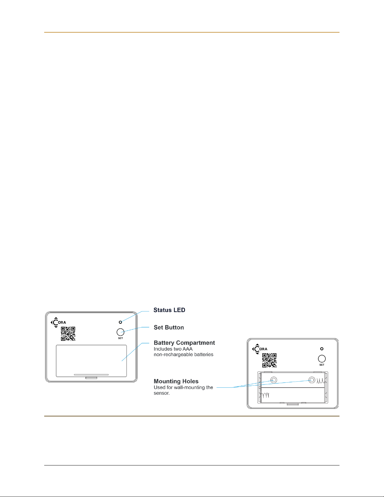
User Interface ......................................................................................................................... 5
Set Button........................................................................................................................... 5
Status Indicators ................................................................................................................. 5
About LoRaWAN .................................................................................................................... 8
Terminology............................................................................................................................ 8
Installation.................................................................................................................................. 9
Test the Vibration Sensor Location Before Installation ............................................................ 9
Applications ............................................................................................................................ 9
Mounting the Device ..............................................................................................................10
Method 1: Install Using Double-Sided Tape .......................................................................10
Method 2: Install Using Mounting Screws...........................................................................11
Method 3: Place in or on an Object ....................................................................................12
Test the Vibration Sensor ......................................................................................................12
Event Notifications and Reports ................................................................................................14
Reset Notifications.................................................................................................................14
Firmware Version...................................................................................................................14
Replacing the Batteries .............................................................................................................15
Configuration and Integration....................................................................................................16
Specifications............................................................................................................................17
Ordering Information .................................................................................................................18
Communication Options.........................................................................................................18
Product SKU..........................................................................................................................18
FCC Statement .........................................................................................................................20
© Copyright 2022 Codepoint Technologies, Inc.
All Rights Reserved

CS1010 Long Range Vibration Sensor – User Guide
Page 3
Getting Started
The CS1040 is a long-range, low-power tilt and vibration sensor supporting LoRaWAN or
Coralink wireless protocols. The sensor provides configurable, real-time notifications or regular
reported statistics.
The sensor can be readily attached to doors, windows, firearms, jewelry boxes, or machinery.
The sensor detects linear or rotational motion in all three dimensions. Small and low profile, the
sensor can be used for a wide variety of applications where detection of vibration or activity is
required.
The CS1040 is powered by two AAA batteries providing 2+ years of operation in typical
conditions. Batteries can be easily replaced.
The sensor can be configured to notify when vibrations exceed thresholds: supporting impulse,
direction, and duration configurations. Powerful statistics monitoring can record duration of
events, maximum, and minimum values as well as direction. The CS1040 has temperature
monitoring, triggers, and battery level notifications.
What’s In the Box
The CS1040 package includes the following:
⧫One (1) Tilt & Vibration Sensor
The sensor is self-contained unit, which can be mounted using the provided double-sided tape
or permanently mounted using the screw holes found in the battery compartment. See
Installation for details and to learn more about proper placement.
Figure 1 –CS1040 Vibration Sensor

CS1010 Long Range Vibration Sensor – User Guide
Page 4
Registering the Device
This step requires a third-party mobile application, which can register new devices. Please
follow the application instructions for registration and activation. Cora devices are typically
registered by scanning the QR code printed on the device housing or attached label.
Attaching to the Network
Once the device is removed from the packaging, it can be activated by pressing the set button.
The device will activate, blinking orange four times and begin issuing join requests. The LED
status indicators is shown in the figure below.
Figure 2 – CS1040 LED Status Indicators
Periodically, the CS1040 will blink red twice when joining the network. Assuming the device is
properly registered on an available network and in range, it should connect. It will blink green
four times indicating it has joined.
Once joined, the vibration sensor can be tested by placing the device in a wet dish or touching
the top sensors with a wet finger. By default, the unit will generate vibration detected events to
notify the application. Reminders and other configurations options are available.
Note: If the CS1040 has not joined within a few minutes, the LED will stop blinking, though it will
continue try to join: ten times in the first hour, then longer intervals over the first week until finally
attempting once every 12 hours. This is done to conserve battery power when the network is not
available for long periods of time. You may reset the join schedule by performing a Network
Reset on the device, see User Interface.
To learn more about the capabilities of the CS1040, see Configuration and Integration.

CS1010 Long Range Vibration Sensor – User Guide
Page 5
User Interface
Set Button
The CS1040 user interface consists of the LED status indicators (Figure 2) and the set button
located on the underside of the device. Pressing the button quickly will send a battery health
message and indicate the current network status discussed previously.
Figure 3 – Performing Network or Factory Reset on the Vibration Sensor
Holding the button will perform a network or factory reset:
⧫Network Reset – Press and hold the SET button for 10 seconds, but less than 25, then
release. The device will reset all LoRaWAN Settings, which does not affect device
operation or configuration. Following reboot, a reset event uplink (confirmed) will be
sent upon rejoining the LoRaWAN network.
⧫Factory Reset – Press and hold the SET button for > 25 seconds, then release. The
device will reset all parameters to factory defaults. Following reboot, a Factory Reset
event uplink (confirmed) will be sent upon rejoining the LoRaWAN network.
Status Indicators
A single button press will indicate the network status. The following table summarizes all the
LED indicators.
LED
Status
Fast Red Blink Two (2) Times
Not Joined
Fast Green Blink Four (4) Times
Joined
Slow Red Blink Two (2) Times
Joining Network
Slow Green Blink Four (4) Times
Joined Network

CS1010 Long Range Vibration Sensor – User Guide
Page 6
Network status blink occurs up to 50 times. Single button press will resume status blink for
another 50 cycles.
Selecting Operating Configuration
The CS1040 can be configured through a series of button presses to operate in one of the
available default settings. Select one of the following settings based on the application
requirements.
Default
Configuration
Description
Button
Presses
Vibration Impulse
Detector
(Default)
Sends notification whenever a vibration or rotation is
detected. Waits three minutes to clear between additional
notifications. Battery health check sent once per day. This
configuration is good to monitor any movement such as
breaking glass, package tampering, opening a drawer, or
safe.
The device ships with this configuration as the default.
Battery life is typically 2+ years.
1
Garage Door Tilt
Detector
Monitors vibration and vertical rotation when attached to a
garage door. Sends notifications when opening, closing,
and hourly reminders when not closed. Battery health
check sent once per day.
Battery life is typically 2+ years.
2
Continuous
Vibration Sensor
Monitors continuous vibration or rotation. Sends
notification when motion begins and ends. Battery health
check sent once per day.
This configuration is useful for monitoring the use of
mechanical equipment. Battery life is typically 2+ years.
3
To change the Sensor configuration:
1. Press the button slowly three (3) times (about 2 – 3 presses per second max) to enter
the configuration selection mode. The device will alternate green/red blink pattern
continuously once entered.
2. Then press the button slowly the corresponding number of times (e.g., 1,2, or 3) to
select the desired configuration.
3. If pressed more than four (4) times, the selection will be cleared and a new selection
specified. If no selection is made in 30 seconds, the device will exit configuration mode
without changes.
4. Once the choice of configuration is made, the device will stop the blink pattern, wait 30
seconds for no further input, apply the configuration change, and perform a network
reset.

CS1010 Long Range Vibration Sensor – User Guide
Page 7
5. After reset, the Sensor will be in the new operating configuration.
The device configuration can also be changed using one or more of the configuration downlink
messages. Custom configurations are possible as well. Consult your application provider for
support.

CS1010 Long Range Vibration Sensor – User Guide
Page 8
About LoRaWAN
LoRaWAN is a low-power, secure, wide area (LPWAN) networking protocol designed to
wirelessly connect devices to the internet in regional, national, or global networks. To use the
CS1040 Vibration Sensor, wireless connectivity to an internet connected LoRaWAN gateway is
required.
For more information about LoRa and LoRaWAN visit the LoRa Alliance webpage:
https://lora-alliance.org/.
Terminology
⧫Message sent from the Vibration Sensor to the network are referred to as “uplink
messages” or “uplinks”.
⧫Messages sent to the Vibration Sensor from the network are referred to as “downlink
messages” or “downlinks”.
⧫Both uplink and downlink messages may be of either “confirmed” or “unconfirmed” type.
Confirmed messages are guaranteed to be delivered but will consume extra wireless
bandwidth and battery life. These mechanisms are analogous to TCP (confirmed) vs
UDP (unconfirmed) protocols used for IP networks.
⧫Before a device, such as the CS1040 Vibration Sensor can transmit messages using
LoRaWAN it must go through a “join” process. The Join process involves key-exchange
with the cloud-hosted network provider (The Things Network, Helium, etc.) and is
defined in the LoRaWAN protocol standard. If connectivity is lost due to RF interference,
power loss or other temporary internet outages, the device will need to rejoin the
network prior to being able to transmit messages. This process happens automatically
but is managed in a battery-efficient manner and may take significant time.

CS1010 Long Range Vibration Sensor – User Guide
Page 9
Installation
Test the Vibration Sensor Location Before Installation
Test your vibration sensor location before affixing it to the surface. Use masking or
painter’s tape to secure the sensor to the surface. Once you have the sensor temporarily
mounted, test it out. Vibrate the detection area while observing the status of the sensor,
the device should blink green once and report the vibration to the attached application.
The vibration sensor can be installed in several ways. It can be affixed to the object via 3M mounting
tape (included), it can be mounted to the object via screws (not included), or it can be placed in or on an
object. Other methods may void the warranty (e.g. glue, epoxy).
You can adjust the device sensitivity to reduce false alerts. Determine if the sensitivity is too low or too
high during your functional test. If the sensor triggers false alerts, you can reduce the sensitivity. If the
sensor does not respond to a condition that should trigger an alert, increase the sensitivity. Aer
adjusting the sensitivity, always perform a functional test.
The vibration sensor is not waterproof and is designed and intended only for indoor use.
Applications
Place the vibration sensor in or on the object to be monitored.
Figure 4 – Potential Vibration Sensor Applications
Factors such as temperature can adversely impact the operation of the sensor. Using the sensor
outdoors and/or in environmental conditions outside those listed in the Environmental section of the
manual (page 26) is discouraged. Additionally, the warranty does not cover the device getting wet.

CS1010 Long Range Vibration Sensor – User Guide
Page 10
Mounting the Device
Method 1: Install Using Double-Sided Tape
Install the Vibration Sensor with double-sided tape on the back of the device.
Double-sided mounting tape is very difficult to remove. Use caution mounting the device to
delicate surfaces.
1. Find a suitable location for the sensor.
Clean the surface well and allow it to dry.
The surface must be free of moisture,
dirt, oil, grease ,or cleaning chemicals.
2. Remove the protective plastic from the
tape by peeling back from a corner.
3. Place the sensor at the desired location,
pressing firmly for at least 5 seconds.

CS1010 Long Range Vibration Sensor – User Guide
Page 11
Method 2: Install Using Mounting Screws
Mount the Vibration Sensor to the surface with screws (not included).
1. Open the battery cover and remove
the batteries to gain access to the
mounting holes on the back of the
sensor.
2. Mount the sensor to the desired
location using screws.
3. Reinstall the batteries and close the
battery cover.

CS1010 Long Range Vibration Sensor – User Guide
Page 12
Method 3: Place in or on an Object
Example 1: In a Drawer
Example 2: In a storage box, safe, security box, or cabinet
Test the Vibration Sensor
⧫It is best to perform a “functional test” of the sensor. For example, if an notification is
desired when a firearm storage box is opened, the functional test should consist of
opening the box. In this example, it is suggested to test opening the box when it is
unlocked. This will test the vibration detection in the case the box was left unlocked.
⧫Have the application running when testing the application. Confirm the correct
responses.
⧫Adjust the sensor sensitivity as needed. Always perform a functional test, if possible,
after adjusting the sensitivity.

CS1010 Long Range Vibration Sensor – User Guide
Page 13
Garage Door Tilt Detection Placement
TODO…

CS1010 Long Range Vibration Sensor – User Guide
Page 14
Event Notifications and Reports
The CS1040 Vibration Sensor has three event notifications:
⧫Vibration Detected – Sensor has detected a vibration (default enabled).
⧫Vibration Cleared – Sensor no longer detects a vibration (default enabled).
⧫Vibration Detected Reminder – Periodic reminder that a vibration is ongoing and has
not been cleared. This notification is not enabled by default and can be configured by the
application.
Additionally, statistics can be enabled to report aggregate sensor event activity:
⧫Vibration Detect Counter
⧫Vibration Clear Counter
⧫Lifetime Vibration Detect Time
⧫Lifetime Vibration Clear Time
⧫Min/Max Vibration Detect Duration
⧫Min/Max Vibration Clear Duration
Statistics are stored in non-volatile memory and will persist through a battery change or dead
battery. Both the statistic reporting and alarms can be configured remotely by sending downlink
messages.
The sensor has a periodic Heartbeat/ Battery-status message that is sent to maintain LoRaWAN
network connectivity and indicate battery status information. The default period for this message
is 60 minutes and may be configured between two (2) minutes minimum and 48 hours
maximum
Reset Notifications
FACTORY RESET uplink messages will be sent after rebooting.
Firmware Version
The firmware information can be retrieved via sending a downlink command. See Configuration
and Integration for details.

CS1010 Long Range Vibration Sensor – User Guide
Page 15
Replacing the Batteries
1. Remove the battery cover by gently
prying with your fingertip or tool at the
edge as shown
2. Remove the old batteries
3. Install two new alkaline non-
rechargeable batteries
Do not mix old and new batteries
4. Close the battery cover

CS1010 Long Range Vibration Sensor – User Guide
Page 16
Configuration and Integration
The CS1040 supports the following settings and features, which are configured via downlink
messages.
Configuration
Description
Units
Default
Vibration
Notification
Reminder Interval
How often the vibration reminder
notification is uplinked.
minutes
10
Vibration
Notification
Reminder Count
The maximum count of reminder
notifications after the vibration is
detected.
count
0xFFFF
Heartbeat / Battery
Interval
Specifies the heartbeat message
uplink interval
minutes
180
(3 hours)
Statistics Interval
How often the statistics are uplinked.
minutes
0: disabled
Clear Statistics
Downlink this message to clear the
stored statistics
N/A
N/A
LED Mode
•LED OFF (Stealth Mode)
•LED ON (Telemetry Only)
•LED ON (Sensor and Telemetry)
N/A
LED ON (Sensor
and Telemetry)
Notification Confirm
/ Unconfirmed
Setting
If set to true, vibration notifications are
confirmed uplink messages. Set to
false to uplink without confirmation.
N/A
CONFIRMED
MESSAGES
Notification Enable
Enable or Disable notifications. If
disabled, the sensor operate as a
counter / statistic only device.
N/A
enabled
Firmware Version
Downlink this message to retrieve the
firmware information
N/A
N/A
For information on decoding and encoding the sensor messages please visit the product page
at Cora CS1040 Vibration Sensor - Codepoint Technologies.

CS1010 Long Range Vibration Sensor – User Guide
Page 17
Specifications
⧫LoRaWAN v1.03 Class A, Coralink™ Class A device
⧫U.S. 923 MHz, E.U. 868 MHz, China 470 MHz, and other frequencies available
⧫Color: White
⧫Dimensions [L x W x D]: 2.56 x 1.97 x 0.69 inches (65 x 50 x 16 mm)
⧫Multi-color status LED
⧫Set button
⧫Power: 2 AAA batteries (3V DC)
⧫Environmental:
Operating Temperature Range: -4°F – 122°F (0°C – 50°C)
Operating Humidity Range: < 95% non-condensing
⧫Intended for indoor use only

CS1010 Long Range Vibration Sensor – User Guide
Page 18
Ordering Information
Communication Options
Prior to ordering, determine the communication requirements:
⧫Application Protocol: Untethered Protocol Buffers (Protobuf) or CP-Flex OCM
⧫Network Protocol: LoRaWAN or Coralink
⧫Operating Region and Frequency: US915, EU868, CN470 (others available upon
request)
⧫Network Providers: TTN, Helium, Chirp stack, etc.
Product SKU
When placing an order use the following SKU structure to determine the specific version, profile,
hardware revision, and packaging needed for the application.
The specification below details the SKU fields and character length.
[id: 6]-[version:2]-[Profile:5]-[Packaging:2]
The fields are defined as follows.
Field name
Character
Length
Description
ID
6
Device six (6) character identification code, Available options:
CS1040 –Revision A Cora Vibration Sensor
Version
2
Device version specification identifying one or key variations that
differentiate this version of the component relative to others. Available
options:
UL –Untethered XMF Application / LoRaWAN protocols
CL –Cora OCM / LoRaWAN protocols
CC –Cora OCM / Coralink protocols
Profile
5
Profile code specifies a configuration that may be unique for an
implementation. Available options:
US9HT –U.S. 915 MHz Region supporting Helium, TTN sub-band 2.
EU8ST –Europe 868 MHz region standard configuration
CN4EZ –China 470 MHz region Easylinkin (Link ware) network
configuration
Other profiles are available upon request.

CS1010 Long Range Vibration Sensor – User Guide
Page 19
Packaging
2
Packaging configuration. This code determines the packaging format for
the device. Available standard options:
00 –Standard reseller packaging. Device identification details
included.
01 –Solution provider / reseller packaging. Only manufacturing ID
provided. Provider receives CSV file with all identifiers to load
into their database.
0X –Custom packaging option. Contact Codepoint for further
information.
Example SKUs:
⧫CS1040-UL-US9HT-00 – Vibration sensor for U.S. region, untethered, supporting
Helium and TTN sub-band 2.
⧫CS1040-UL-EU8ST-01 – Vibration sensor for Europe region, untethered, standard
configuration, packaged for solution provider distribution.
CS1040-CL-US9HT-00 – Vibration sensor configured for Cora OCM and CP-Flex cloud
stack integration, Supports OCM V2 protocol specifications.

CS1010 Long Range Vibration Sensor – User Guide
Page 20
FCC Statement
This equipment has been tested and found to comply with the limits for a Class B digital device,
pursuant to part 15 of the FCC Rules. These limits are designed to provide reasonable
protection against harmful interference in a residential installation. This equipment generates,
uses, and can radiate radio frequency energy and, if not installed and used in accordance with
the instructions, may cause harmful interference to radio communications. However, there is no
guarantee that interference will not occur in a particular installation. If this equipment does
cause harmful interference to radio or television reception, which can be determined by turning
the equipment off and on, the user is encouraged to try to correct the interference by one or
more of the following measures:
⧫Reorient or relocate the receiving antenna
⧫Connect the equipment into an outlet on a circuit different from that to which the receiver
is connected
⧫Increase the separation between the equipment and receiver
⧫Consult the dealer or an experienced radio / TV technician for help
⧫This device complies with part 15 of the FCC Rules. Operation is subject to the following
two conditions:
1. This device may not cause harmful interference
2. This device must accept any interference received, including interference that may
cause undesired operation.
Any changes or modifications not expressly approved by the party responsible for compliance
could void the user’s authority to operate the equipment.
Note: The manufacturer is not responsible for any radio or TV interference caused by
unauthorized modifications to this equipment. Such modifications could void the user’s authority
to operate the equipment.
FCC RF radiation exposure statement
This equipment complies with FCC RF radiation exposure limits set forth for an uncontrolled
environment. This device and its antenna must not be co-located or operating in conjunction
with any other antenna or transmitter. “To comply with FCC RF exposure compliance
requirements, this grant is applicable to only Mobile Configurations. The antennas used for this
transmitter must be installed to provide a separation distance of at least 20 cm from all persons
and must not be co-located or operating in conjunction with any other antenna or transmitter.”
Table of contents
Other CORA Accessories manuals