BIFFI ICON3000 Series Setup guide

Installation, Operation and Maintenance Manual
MDE 257 Rev. 1
March 2021
Biffi ICON3000
Advanced Maintenance Instructions
Copyright © Biffi. The information in this document is subject to change without notice. Updated data sheets can be obtained from our website www.biffi.it or from your nearest Biffi Center:
Biffi Italia s.r.l. - Strada Biffi 165, 29017 Fiorenzuola d'Arda (PC) – Italy PH: +39 0523 944 411 – biffi_itali[email protected]

Installation, Operation and Maintenance Manual
MDE 257 Rev. 1
March 2021
Revision Details
Revision Details
Rev. Date Description Prepared Checked Approved
1 March 2021 General update (Migration to new template)
0 04-10-2018 A. B L. V
Revision Details

Installation, Operation and Maintenance Manual
MDE 257 Rev. 1
Table of Contents
March 2021
iTable of Contents
Table of Contents
Section 1: Introduction
Introduction...........................................................................................................................1
Section 2: Reserved Passwords
Reserved Passwords............................................................................................................2
Section 3: Restricted Menu Routines
3.1 Torque Stop Zone.......................................................................................... 5
3.2 Speed Bypass ................................................................................................ 5
3.3 Voltage Span................................................................................................. 6
3.4 1 P.man......................................................................................................... 6
3.5 HW Config .................................................................................................... 6
3.6 Positioner...................................................................................................... 7
3.7 Request......................................................................................................... 7
3.8 Fail Safe......................................................................................................... 7
3.9 Bus An-Out.................................................................................................... 7
3.10 Direction Test................................................................................................ 7
3.11 Card Ain/Aout ............................................................................................... 8
3.12 Bluetooth Extension Antenna or Bluetooth.................................................... 8
3.13 IRDA.............................................................................................................. 8
3.14 Bus Protocol.................................................................................................. 9
3.15 PID................................................................................................................ 9
3.16 Reserved Routines......................................................................................... 9
3.16.1 SW Type.......................................................................................... 9
3.16.2 Term Board ..................................................................................... 9
3.16.3 Additional Var. ................................................................................ 9
3.16.4 Reversal Delay............................................................................... 11
3.16.5 Backlight....................................................................................... 11
3.16.6 4 - 20 mA Config ........................................................................... 12
3.16.7 Current Sensor.............................................................................. 12
3.16.8 Torque Sensor............................................................................... 13
3.16.9 Speed Band................................................................................... 13
3.16.10 Base Temp. Ref.............................................................................. 13
3.16.11 LCD Temp. Ref............................................................................... 13
3.16.12 TERM Temp. Ref. ........................................................................... 13
3.16.13 Torque Function............................................................................ 13
3.16.14 Interlock Mode ............................................................................. 13
3.16.15 Sleep............................................................................................. 13
3.16.16 MR in Sleep................................................................................... 13
3.16.17 New FW ........................................................................................ 13
3.16.18 Serial CMD .................................................................................... 14
3.16.19 Loc/Rem ....................................................................................... 14
3.16.20 Bluetooth Code............................................................................. 14
3.16.21 EFS Duty ....................................................................................... 14
3.16.22 Spring Action................................................................................ 14
3.16.23 EFS EL.CMD................................................................................... 14
3.16.24 ESD Input Mode............................................................................ 14
3.16.25 CMD-filter..................................................................................... 14
3.16.26 ESD/INT-filter................................................................................ 14

Table of Contents
March 2021
Installation, Operation and Maintenance Manual
MDE 257 Rev. 1
ii Table of Contents
Section 4: Alarm "Configuration n°"
4.1 Object List of ICON3000.............................................................................. 16
Section 5: Alarm "Hardware n°"
Section 6: Terminal Board Types
6.1 Terminal Board Adaptor (TBA) Card.......................................................... ...35
Section 7: Configuration
Configuration.........................................................................................................36
Section 8: Test Point and Connector Base Card
Test Point and Connector Base Card........................................................................39
Section 9: Firmware Of DE9425 HW REV ≥ 00B
Firmware Of DE9425 HW REV ≥ 00B.......................................................................40

Installation, Operation and Maintenance Manual
MDE 257 Rev. 1
March 2021
1
Introduction
Section 1: Introduction
Section 1: Introduction
This manual should be used in conjunction with the Installation, Operation and Maintenance Manual
(IOM) of the ICON3000.
This manual supplies an additional set of instructions for service and troubleshooting and describes
the parameters available in the RESTRICTED MENU.
The routines contained within the RESTRICTED menu can significantly modify the functionality of
the actuator; therefore, access to and utilization of the RESTRICTED menu should be limited to only
trained and authorized technicians.
If any parameter in the RESTRICTED menu is changed, power must be cycled on the actuator for the
changes to take effect.

March 2021
Installation, Operation and Maintenance Manual
MDE 257 Rev. 1
2Reserved Passwords
Section 2: Reserved Passwords
Section 2: Reserved Passwords
The VIEW and SETUP features available through the Local Operator Interface allows the user to set
actuator characteristics according to the needs of the process and to view diagnostic
messages and status.
To enter the SETUP menu a password is required. Three levels of password are available:
1. Password level 0: This is the "user" password and consists of 4 alphanumeric characters.
The actuator is supplied with the password "0000" (four zeros) from the factory. The user
can change this factory password as described in the ICON3000 IOM.
2. Password level 1: This password allows the user all of the functionality afforded by
Level 0, but also allows the NAMEPLATE routine to be entered and changed. Nameplate
data is normally entered in the factory. The Level 1 password (not "0000") is entered in the
same fashion as Level 0.
3. Password level 2: This password offers all the functionality of Levels 0 and 1, and also
offers entry into the RESTRICTED routine of the ACTUATOR SETUP menu. Special routines
can be found within the RESTRICTED routine that are generally used to enable and disable
hardware and software modules, and calibrate the ICON3000's sensors. There is a special
procedure for entering the Level 2 password, which is as follows:
• Enter VIEW and SETUP menu as described in the IOM of the actuator.
• Select language.
• Select SETUP mode.
• Enter password:
— Select the 1st character of password, and then press YES.
— Select the 2nd character of password, and then press YES.
— Select the 3rd character of password, and then press YES.
— Select the 4th character of password, and then press YES and keep this push-button
pressed down until the display shows the message "PASSWORD CORRECT."
The button must be kept pushed down for approximately 10 seconds for the
password to be accepted.
• Confirm SETUP mode.
• Confirm ACTUATOR SETUP.
• Scroll the ACTUATOR SETUP routines until the display shows the message “RESTRICTED.”
Press YES to enter.
• View or change the restricted parameter(s), and then EXIT from the menu.

Installation, Operation and Maintenance Manual
MDE 257 Rev. 1
March 2021
3
Reserved Passwords
Section 2: Reserved Passwords
Upon having changed any parameter in the RESTRICTED menu, actuator power must be cycled in
order for the changes to take effect.
Contact Emerson Lifecycle Services to request access to the Level 1 and Level 2 passwords.
The list below shows the available routines in the ACTUATOR SETUP menu:
• Stroke limits
• Torque set up
• PST set up*
• ESD set up*
• EFS/PST*
• Remote controls
• Local controls
• Output relays
• Positioner*
• Fail Safe*
• Out 4 - 20 mA*
• Interlock*
• 2 speed timer
• Bus*
• Miscellaneous
• Restricted
• Reserved
The routines with marked with an asterisk (*) are present only if the relevant electronic cards are
present. Should the bus interface be LonWorks, then the BUS routine will display as "FDI CONTROL."
The RESTRICTED menu routine will only appear if the Level 2 password is entered.

March 2021
Installation, Operation and Maintenance Manual
MDE 257 Rev. 1
4Resticted Menu Routines
Section 3: Restricted Menu Routines
Section 3: Restricted Menu Routines
Within the RESTRICTED menu, certain routines are grouped into RESTRICTED and RESERVED
categories. To access the RESERVED routines, scroll through each of the RESTRICTED routines
and when the menu displays EXIT OK, press the NO push-button. Each routine is listed as follows:
Restricted Routines
• Torque stop zone
• Speed bypass
• Voltage span
• 1 P.man
• HW config.
• Positioner
• Request
• Fail Safe
• Bus An-out
• Direction test
• Card Ain/Aout
• BLT ext. antenna or Bluetooth
• IrDA
• Bus protocol
• PID

Installation, Operation and Maintenance Manual
MDE 257 Rev. 1
March 2021
5
Resticted Menu Routines
Section 3: Restricted Menu Routines
Reserved Routines
• SW type
• Term. board
• Additional var.
• Reversal delay
• Backlight
• 4 - 20 mA config.
• Current sensor
• Torque sensor
• Speed band
• Base temp. ref.
• LCD temp. ref.
• Term. temp. ref.
• Torque function
• Interlock mode
• Sleep mode
• MR in sleep
• New FW
• Serial cmd
• Loc/Rem
• Bluetooth code
• EFS duty
• Spring action
• EFS. EL. CMD
• ESD input mode
• CMd filter
• ESD-INT filter
3.1 Torque Stop Zone
If the torque limit is reached in the position interval “0 to torque stop zone” and “100-torque
stop zone to 100” and opening or closing stroke limits are set by torque, then the ICON3000
considers the reached position as “end of travel.” If the torque limit is reached at a position between
“torque stop zone” and “100-torque stop zone," then the ICON3000 will generate an alarm. If the
torque limit is not reached the warning “wrong stroke limit“ is generated. Standard value = 5%.
3.2 Speed Bypass
This is the time needed to update the motor speed after receipt of an open or close command.
Standard value = normally >1.5 seconds (depends on actuator type).

March 2021
Installation, Operation and Maintenance Manual
MDE 257 Rev. 1
6Resticted Menu Routines
Section 3: Restricted Menu Routines
3.3 Voltage Span
This function allows to recalibrate the sensor that measures the main voltage supply.
The recalibration procedure is as follows:
Using a multimeter, measure the value of the voltage supply on terminals L1/L2 of the terminal
board. On the actuator display, enter the same value measured by the multimeter and then press
YES. The new value is accepted only if it is at least 1 V different from the previous value. Pressing
YES will not effect any change in voltage sensor calibration if the value indicated on the display is
not changed.
3.4 1 P.man
This function is also known as "Gear Relaxation," and functions by backing off the motor a small
amount at either end of the valve travel. The effect is to reduce compressive stress on the actuator
gears and facilitate engagement of the manual override declutch lever. This routine is set in-house.
Standard value = DISABLED.
3.5 HW Config
This function is used to select the fieldbus control option. The following options can be selected:
• Base (No bus control)
• Lon (Lonworks)
• Mod-bus (Modbus RTU)
• Prof-V0 (Profibus DPV0)
• Mod-m (Modbus RTU)
• FF (Foundation Fieldbus)
• Hart (Hart)
• Prof-V1 (Profibus DPV1)
• Prof-V1r (Profibus DPV1 redundant)
• MOD-Dw (Modbus Dewa)
• Prof-V2 (Profibus DPV2)
• Prof-V2r (Profibus DPV2 redundant)
If the “base” option is set, then a fieldbus interface card is not required. If one of other options is
chosen, the ICON3000 base card must be equipped with the appropriate bus interface card. It is also
necessary to set the parameter “bus protocol” that sets the type of communication protocol
between the base card and the bus interface card. The “BUS” routine appears in the ACTUATOR
SETUP menu and the relevant parameters (node address, baud rate, etc.) can be viewed and changed
as described in the ICON3000 IOM. If the option LONWORKS is chosen, the “BUS” routine in the
ACTUATOR SETUP menu changes to "FDI CONTROL."

Installation, Operation and Maintenance Manual
MDE 257 Rev. 1
March 2021
7
Resticted Menu Routines
Section 3: Restricted Menu Routines
Figure 1 Base Card of ICON3000 Equipped with a Bus Card
3.6 Positioner
This routine allows the user to enable or disable the positioner function. If the option ENABLED is set,
the POSITIONER routine appears in the ACTUATOR SETUP menu and the relevant parameters
(dead band, motion inhibit time, etc.) can be viewed and changed as described in the ICON3000 IOM.
The type of position request signal (from 4 - 20 mA input or from bus) is set by the routine REQUEST.
3.7 Request
This routine allows the user to select the type of position request signal used in the POSITIONER
routine. The options available are 4 - 20 mA and BUS. Set BUS. if the positioner will receive the
position request from bus interface and set “4 - 20 mA” if the position request signal will be received
from the optional analog 4 - 20 mA input/output module (named "Ain/Aout"). The parameter
"CARD Ain/Aout" must be set to PRESENT.
3.8 Fail Safe
This routine allows the user to enable or disable the fail safe action performed by the actuator
in cases of remote control failure via bus or via 4 - 20 mA analog input. If the option ENABLED is
chosen, the routine FAIL SAFE appears in the ACTUATOR SETUP menu and the relevant parameters
(action and delay) can be viewed and changed as described in the ICON3000 IOM.
3.9 Bus An-Out
This parameter is set in-house. The standard value is “TORQUE.”
3.10 Direction Test
This parameter is used in the ICON3000 in the direction test. If the test fails a SPEED SENSOR alarm is
generated. The standard value for ICON3000 is 1.

March 2021
Installation, Operation and Maintenance Manual
MDE 257 Rev. 1
8Resticted Menu Routines
Section 3: Restricted Menu Routines
This optional card is used in place of the
Terminal Board Adaptor card when an analog
4 – 20 mA input and output signal is requested.
3.11 Card Ain/Aout
This parameter has two options: PRESENT or ABSENT. Set PRESENT if the base card is equipped with
the optional 4 - 20 mA input/output card ("Ain/Aout") that provides an analog 4 - 20 mA input and
output to the actuator. The routine OUT 4 - 20 mA appears in the ACTUATOR SETUP menu and the
relevant parameters (e.g. polarity) can be viewed and changed as described in the ICON3000 IOM.
A report message can also be viewed as described in the same IOM.
Set the parameter to ABSENT if the terminal board adaptor card (see Section 6.1) has been installed
instead of the 4 - 20 mA "Ain/Aout" card. Setting this parameter incorrectly can result in a hardware
alarm (refer to the ICON3000 IOM for details on this alarm).
Figure 2 Ain/Aout Card
Figure 3 ICON3000 Base Card Equipped with Ain/Aout Card
3.12 Bluetooth Extension Antenna or Bluetooth
This parameter has two options: ENABLED or DISABLED.
If the BLUETOOTH parameter is enabled, the RS232 service line on the base card will not be available.
The BLUETOOTH parameter needs to be set to DISABLED before using the RS232 service line.
Therefore, it is recommended to set BLUETOOTH to DISABLED.
3.13 IRDA
This function is not implemented. It is normally set to DISABLED.

Installation, Operation and Maintenance Manual
MDE 257 Rev. 1
March 2021
9
Resticted Menu Routines
Section 3: Restricted Menu Routines
3.14 Bus Protocol
This parameter allows the user to select the communication protocol between the base card and
fieldbus interface card. I20 and I24 are the two available options. Refer to the relevant ICON3000 bus
protocol manual to correctly set this parameter.
3.15 PID
This function is not implemented. It is normally set to DISABLED.
3.16 Reserved Routines
3.16.1 SW Type
This routine must be set to "ICON."
3.16.2 Term Board
This routine must be set to “I24_V4.”
3.16.3 Additional Var.
The standard value is “MASK” and the following data can be viewed:
• Output torque
• Motor speed
• Main voltage
• Current
• Temperature
• Time
• Date
• Alarm
• Warning
• Ktemp
• Mot temp
• Term temp
• Log status
• Wireless report
• Node report*
• FDI report*
• Base report
• Term report
• Ain/Aout report*
• EFS report*
The data with * are present only if the relevant modules are present.

March 2021
Installation, Operation and Maintenance Manual
MDE 257 Rev. 1
10 Resticted Menu Routines
Section 3: Restricted Menu Routines
With the option VIEW, additional data useful for maintenance can be viewed:
• Battery Value: value in volt of the battery
• Remote Command: status of the DIs => bit0: not used, bit1: ESD, bit2: Open, bit3: Close,
bit4: Stop, bit5: Man, bit6: Int_CL, bit7: Int_OP
• Encoder Abs Position: 0 to 2196479
• Encoder Status: bit0 = CCW, bit7 = calibrated, bit8 = communication error, bit9 = CW/CCW
wrong communication
• Encoder wheel 1: 0 to 2047
• Encoder wheel 2: 0 to 2047
• Encoder wheel 3: 0 to 2047
• Encoder limit 0%
• Encoder limit 100%
• Encoder Error: error counter (communication between Base card and Encoder)
• Counter: position %
• Pic Word 1: Status => (bit0: wake up H8, bit2: encoder OK, bit10: Position OK,
bit11: Low bat, bit12: 24 V_ext_present, bit13: 13 V dc present, bit 14: CRC PIC OK,
bit15: calibration in progress)
• Pic Word 2: Push-buttons/Selector => bit0: remote, bit1: Local, bit2: stop, bit3: close,
bit4: open, bit5: not configured as ICON
• Pic Word 3: encoder status => bit0 = CCW, bit7 = calibrated, bit8 = communication error,
bit9 = CW/CCW wrong communication
• Pic Word 4: encoder error counter (communication between Base card and Encoder)
• Pic Word 5: reserved
• Pic Word 6: reserved
• Pic Word 7: reserved
• Pic Word 8: reserved
• Pic Word 9: reserved
• Pic Word 10: reserved
• Pic Word 11: reserved
• Pic Word 12: reserved
• Pic Word 13: reserved
• Pic Word 14: reserved
• Pic Word 15: configuration => bit0: battery present, bit1: CCW
• Pic Word 16: reserved
• Pic Port A: status of the pic port A
• Pic Port B: status of the pic port B
• Pic Port C: status of the pic port C
• Pic Port D: status of the pic port D
• Pic Port E: status of the pic port E
• Pic AN0: PIC analog input (battery value in bit)

Installation, Operation and Maintenance Manual
MDE 257 Rev. 1
March 2021
11
Resticted Menu Routines
Section 3: Restricted Menu Routines
• Port 4 an0: not used
• Port 4 an1: not used
• Port 4 an2: not used
• Port 4 an3: main voltage in bits
• Port 4 an4: motor current in bits
• Port 4 an5: terminal board type in bits
• Port 4 an6: auxiliary contact of K1 contactor in bits
• Port 4 an7: current range out in bits
• Port 9 an0: auxiliary contact of K2 contactor in bits
• Port 9 an1: status of Bluetooth module in bits
• Port 9 an2: reserved. Not used for ICON3000
• Port 9 an3: motor thermostat in bits
• Port 9 an4: motor temperature in bits
• Port 9 an5: not used
• Port 9 an6: heater cmd in bits
• Port 9 an7: backlight cmd in bits
3.16.4 Reversal Delay
This function sets the delay implemented as part of the instantaneous reversal feature (i.e. reverse
motor rotation). Standard value is 1.1 seconds.
3.16.5 Backlight
The standard value is AUTO. The backlight of display automatically switches off 2 minutes after the
last operation with the local operator interface. This option increases the life of the display since the
backlight is powered only when using the local operator interface.
With the option “ON,” the backlight of the display is always powered. Use this option only when
absolutely necessary.

March 2021
Installation, Operation and Maintenance Manual
MDE 257 Rev. 1
12 Resticted Menu Routines
Section 3: Restricted Menu Routines
3.16.6 4 - 20 mA Config
This routine is used to calibrate the 4 - 20 mA input and outputs. This is normally done in-house.
Should it be necessary to recalibrate the 4 - 20 mA input and output, this needs to be conducted in
two steps.
Reconfigure the limits of the A/D and D/A converters of the base card as follows:
• Enter VIEW and SETUP menu as described in the ICON3000 IOM.
• Select the language.
• Select SETUP mode.
• Enter the Level 2 password.
• Select ACTUATOR SETUP.
• Scroll the list of routines and press YES when the message displayed is “RESTRICTED.”
• Press YES to scroll the list of “RESTRICTED” routines and press NO when the message
displayed is “EXIT OK?”.
• Press YES until the message displayed is “4 - 20 mA CONFIG. CHANGE?”
• Press YES to enter the “4 - 20 mA CONFIG.” routine. The message displayed will be
“READ OK?”.
• Press YES to view or change the configured values corresponding to I = 4 mA (from 0 to
2000), I = 20 mA (from 2000 to 4095), O = 4 mA (from 0 to 2000), O = 20 mA (from 2000 to
4095). Press YES to confirm and skip to next step or press NO to change. Values out of range
cause a CONFIGURATION alarm.
• Or press NO to skip to “SETUP OK?”.
• When the message displayed is “SETUP OK?” press NO to exit or press YES to recalibrate:
— Connect a 4 - 20 mA current generator to terminals B8/B9 and a multimeter in mA
to terminals C10/B7 in accordance with the electrical diagrams.
— The message displayed is “I = 4 mA=xxxx.”
— Set the current generator to 4 mA. The displayed value should be from 0 to 2000.
Press YES.
— Set the current generator to 20 mA. The displayed value should be from 2000 to
4095. Press YES.
— Press NO until the multimeter indicates 4 mA. The displayed value should be from
0 to 2000. Press YES.
— Press NO until the multimeter indicates 20 mA. The displayed value should be
from 0 to 2000. Press YES.
— Exit from the configuration menu.
3.16.7 Current Sensor
This routine includes the calibration values of the current sensor. Calibration of the current sensor
is done in-house. Enter the routine only if a new setting is required. There are two options available:
READ and SETUP. In READ mode the operator can view and change the values corresponding to
currents 2 A, 3.5 A, 7 A, 15 A, and 30 A via the local operator interface. Do not enter SETUP mode.
When the message displayed is “CURRENT SENSOR CHANGE?” press NO to skip to next routine or
press YES to enter. The display will show the message “READ OK?” Press YES to view or change the
values. If the NO push-button is pressed the message displayed will be “SETUP OK?” Press NO to exit.

Installation, Operation and Maintenance Manual
MDE 257 Rev. 1
March 2021
13
Resticted Menu Routines
Section 3: Restricted Menu Routines
3.16.8 Torque Sensor
This routine is used in-house to set torque sensor parameters. Do not enter into this routine; if this
occurs, press NO when the message TORQUE SENSOR CHANGE? is displayed.
3.16.9 Speed Band
The standard value is 10. The value is automatically adjusted as a function of the number of motor
poles stated in the motor data section of the NAMEPLATE menu.
3.16.10 Base Temp. Ref.
The standard value is 2 °C. When the temperature inside the electronics compartment is less than the
above value, the heater of the base card is powered.
3.16.11 LCD Temp. Ref.
The standard value is -5 °C. When the temperature inside the terminal board compartment is less
than the above value, the heater of the LCD display is powered.
3.16.12 TERM Temp. Ref.
The standard value is 0 °C. When the temperature inside the terminal board compartment is less
than the above value, the heater on the terminal board cards is switched on.
3.16.13 Torque Function
This parameter is normally set to “STANDARD.”
3.16.14 Interlock Mode
This parameter is normally set to “STANDARD” and INTERLOCK function is available. If the
INTERLOCK MODE is set in “ADVANCED” the ICON300 use the Interlock input as PST commands.
INTERLOCK OPEN becomes command to carry out PST in open direction. INTERLOCK CLOSE
becomes command to carry out PST (Partial Stroke Test) in close direction. PST function are
performed only if the actuator is fully open or closed.
3.16.15 Sleep
This parameter is normally set to “DISABLED.” Use the option to enable SLEEP function.
Refer to the ICON3000 Sleep Mode manual for a detailed description of this function.
3.16.16 MR in Sleep
This parameter is normally set to “OFF.” Use this option to set MR to OFF or ON when the
SLEEP function is enabled. Refer to the ICON3000 Sleep Mode manual for a detailed description of
this function.
3.16.17 New FW
This parameter is normally set to “DISABLED.” Use the option ENABLED only if the base card
firmware must be updated. Set the back to DISABLED after upgrading the firmware. Refer to
the appropriate instructions relevant to firmware upgrades.

March 2021
Installation, Operation and Maintenance Manual
MDE 257 Rev. 1
14 Resticted Menu Routines
Section 3: Restricted Menu Routines
3.16.18 Serial CMD
This parameter is normally set to “DISABLED.” Use this option to enable OP/CL/STOP command from
Bluetooth, RS232 interface.
3.16.19 Loc/Rem
This parameter is normally set to “DISABLED.” Use this option to enable local OP/CL/STOP commands
also when the local selector is in REMOTE (LOC+REM).
3.16.20 Bluetooth Code
This parameter is normally set to “S/N.” Use this option to select Bluetooth code between
“S/N” = actuator serial number and “V/TAG” = valve tag.
3.16.21 EFS Duty
Reserved. Not used by ICON3000.
3.16.22 Spring Action
Reserved. Not used by ICON3000.
3.16.23 EFS EL.CMD
Reserved. Not used by ICON3000.
3.16.24 ESD Input Mode
Reserved. Not used by ICON3000.
3.16.25 CMD-filter
This parameter is normally set to 1. The maximum value is 32. Use this option to set the filter level of
OP/CL/ST commands.
Set the above parameter to 100 if a fast reaction is required in response to open and close commands.
The setting causes the following changes:
• Control mode in local and remote changes to “push to run.”
• Filtering reduced to the minimum.
3.16.26 ESD/INT-filter
This parameter is normally set to 1. The maximum value is 32. Use this option to set the filter level of
ESD/INT commands.

Installation, Operation and Maintenance Manual
MDE 257 Rev. 1
March 2021
15
Alarm "Conguration n°"
Section 4: Alarm "Configuration n°"
Section 4: Alarm "Configuration n°"
If the checksum of the EEPROM memory containing the data of ICON3000 settings is wrong,
exit the alarm “CONFIGURATION n°” (refer to the ICON3000 IOM).
Every configuration parameter is called “OBJECT or OBJ” and is characterized by an
“OBJ number.” The number “n°” indicates the number of the OBJ that is out of range.
To clear the configuration alarm, it is necessary to set the correct value using the VIEW and SETUP
features as described in the ICON3000 IOM.
If the alarm message is “CONFIGURATION OBJ 9999,” only one of the actuator parameters needs to
be changed. For example: enter the SETUP menu, then ACTUATOR SETUP, then TORQUE SETUP, then
and increase or decrease the closing torque by 1%. When the alarm message disappears, reenter the
SETUP menu, then ACTUATOR SETUP, then TORQUE SETUP, and then set the previous value.
If the alarm message is “CONFIGURATION OBJ 720 or 721 or 722 or 723,” proceed as follows:
• Repower the actuator and observe the first message of the display. If the ICON3000 base
card is equipped with the “Ain/Aout” optional card, check the following parameters in the
“RESTRICTED” menu routines:
— Term board: should be set to “I24 V4”
— Card Ain/Aout: should be set to “PRESENT”
If the settings are wrong, enter the correct values and then proceed to cycle power on
the actuator.
In the following table is the list of the Objects (or parameters). The OBJECTS are sorted
according to the actuator menu. Every line of the table gives a complete description of the Object
by means of “OBJ n°,” “normal value,” "function," and “description and ranges.”

March 2021
Installation, Operation and Maintenance Manual
MDE 257 Rev. 1
16 Alarm "Conguration n°"
Section 4: Alarm "Configuration n°"
4.1 Object List of ICON3000
Table 1. Stroke Limits and Torque Setup
Actuator Setup
Obj n° Value Function Description
102 CW Close direction CW, CCW
100 Off Close limit type Torque, position
101 Off Open limit type Torque, position
506 70 Closing torque From 40 to 100%
505 75 Opening torque From 40 to 100%
510 60 Breakout in closing From 40 to 100%
511 40 Peak run in closing From 40 to 100%
512 80 Ending in closing From 40 to 100%
513 90 Breakout zone in closing From 0 to 100%
514 10 Ending zone in closing From 0 to 100%
515 90 Breakout in opening From 40 to 100%
516 40 Peak run in opening From 40 to 100%
517 80 Ending in opening From 40 to 100%
518 20 Breakout zone in opening From 0 to 100%
519 80 Ending zone in opening From 0 to 100%
Table 2. ESD Setup
Actuator Setup
Obj n° Value Function Description
600 Off ESD action Off, close, open, stay put, go to
position %
601 50 ESD position From 0 to 100
605 ESD<thermostat ESD and motor thermostat alarm ESD<thermostat, ESD>thermostat
606 ESD<local stop ESD and torque alarm ESD<torque limit, ESD>torque limit
607 ESD<local stop ESD and local stop ESD<local stop, ESD>local stop
608 ESD<local selector ESD and local selector in LOCAL ESD<local selector, ESD>local selector
609 ESD<local selector in OFF ESD and local selector in OFF ESD<local selector in OFF,
ON=ESD>local selector in OFF
611 ESD<2 speed timer ESD and 2-speed timer ESD<2-speed timer, ESD>2-speed timer
602 Present ESD signal type ESD carried out: with signal absent or
with signal present
Other manuals for ICON3000 Series
10
Table of contents
Other BIFFI Controllers manuals
BIFFI
BIFFI ICON3000 Series User manual
BIFFI
BIFFI RPD Series User manual
BIFFI
BIFFI F02 manual
BIFFI
BIFFI ALGA Series User manual

BIFFI
BIFFI RP14 User manual

BIFFI
BIFFI ECU 1000 Manual
BIFFI
BIFFI FCB Series Operating instructions
BIFFI
BIFFI TPS Series User manual
BIFFI
BIFFI OLGAS-H User manual
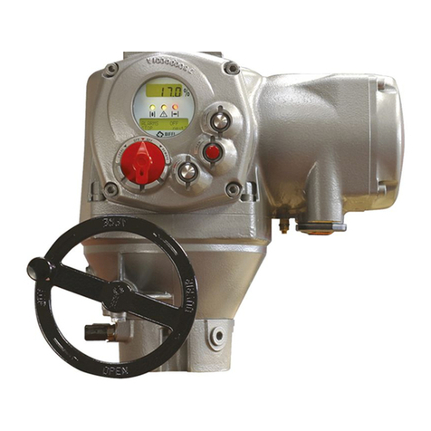
BIFFI
BIFFI F01-2000 Parts list manual
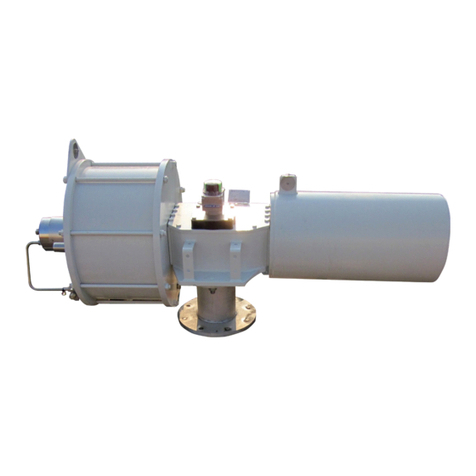
BIFFI
BIFFI ALGAS-QA EAC User manual

BIFFI
BIFFI ALGA - EAC User manual
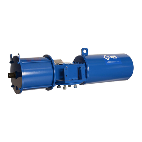
BIFFI
BIFFI ALGAS User manual
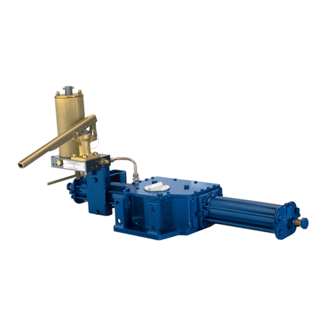
BIFFI
BIFFI GIG User manual
BIFFI
BIFFI HLRA User manual
BIFFI
BIFFI OLGAS-QA User manual
BIFFI
BIFFI OLGA Series User manual
BIFFI
BIFFI HLA Series User manual
BIFFI
BIFFI GIGS Series User manual
BIFFI
BIFFI HLA User manual
