Coretec VCX-2401-E User manual

INSTALLATION AND OPERATING INSTRUCTIONS
Revision Date: April 5, 2012
VCX-2401-E MPEG-2/JPEG Encoder, IP
VCX-2401-ER MPEG-2/JPEG Encoder, IP Rack Mount
Core Tec Communications, LLC
2950 Lake Emma Rd
Suite 1030
Lake Mary, FL 32746 USA
Phone (407) 331-0547
Fax (407) 331 0656
www.coretec.com
Technical Support:
U.S. 877-331-0547
(Toll Free)
Elsewhere: 407-331-0547

VCX-2401-E Installation and Operating Instructions Page 2
Table of Contents
Introduction..................................................................................................................................... 3
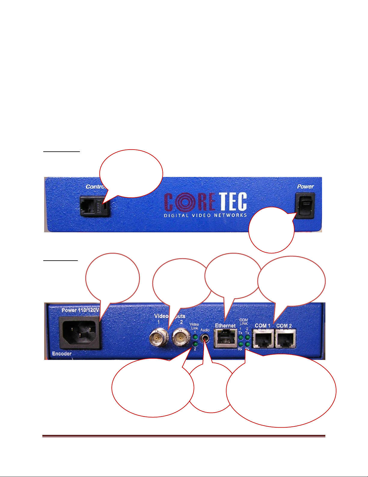
Familiarization with the VCX2401-E......................................................................................... 4
Com Port Data Interface ............................................................................................................. 5
Video Input Interface.................................................................................................................. 5
Ethernet Interface........................................................................................................................ 5
Power .......................................................................................................................................... 5
Display (full size encoder only).................................................................................................. 5
Mounting the Encoder................................................................................................................. 6
Quick Start...................................................................................................................................... 7
If user wishes to configure settings with VCX2401-E via COM Port or Network:................... 7
Updating Firmware with TFTP..................................................................................................... 10
IP Configuration............................................................................................................................ 11
Overview................................................................................................................................... 11
Initial IP Addressing................................................................................................................. 11
Connecting to Unit........................................................................................................................ 13
Program Commands...................................................................................................................... 20
Network Setup .......................................................................................................................... 20
Common Commands ................................................................................................................ 22
Encoder Commands.................................................................................................................. 23
COM Port Setup........................................................................................................................ 23
OSD COMMANDS (On Screen Display)................................................................................ 25
Video Commands...................................................................................................................... 26
FTP Commands ........................................................................................................................ 28
SAP Settings ............................................................................................................................. 29
SNMP Settings.......................................................................................................................... 31
Miscellaneous Settings.............................................................................................................. 31
Specifications................................................................................................................................ 33
Model Numbers ............................................................................................................................ 35
Appendix A................................................................................................................................... 35
Pinouts....................................................................................................................................... 35
Com Port Data Interface Pin Out (uses RJ-45 Plug)............................................................. 35
Standard Ethernet Pin Out .................................................................................................... 36
RJ-11 to Serial Interface Adaptor Pinout.............................................................................. 36

VCX-2401-E Installation and Operating Instructions Page 3
Troubleshooting........................................................................................................................ 37
Introduction
The model VCX-2401-E is the stand-alone MPEG-2/JPEG version of the VCX family
and is housed in a 19-inch 1U rack mount case with a display, control port and a universal AC
power supply. The configuration of the VCX-2401-E-H is akin to desktop like devices being 1U
high but only 8.5 inches wide. The model VCX-2401–E-R is a rack mounted card only used in
the 4U 19-inch rack unit. See Accessories R-12.
The VCX Digital Video transport system consists of the video encoder and a decoder.
These will make up an encoder/decoder pair providing the capability for one-way end-end
transmission of the compressed digital video stream in one of three formats. The two formats are
MPEG2 standard ISO/IEC 13818-2 and JPEG standard ISO 10918-1. The transportation process
is performed by transmitting and receiving IP packets at data rates in the 64kbps to 4.0 Mbps
range. The encoding-decoding process is applied to an NTSC (or PAL) video input, selected in
software.
The video encoder converts the Analog Video to a Serial Digital signal, which is
multiplexed with any data sub-channels present. The stream is then formatted into a series of IP
packets sent to the network through a standard Ethernet connection.
Modification of video format and resolution, data sub-channel characteristics, and basic
IP parameters is achieved through one of the following means:
a) Terminal Program
b) Telnet through the Ethernet connection
c) Watchdog CCS
d) SNMP
e) Web Interface
The video decoder receives the IP packets, separates the video data from the data sub-
channels, and converts the video data to analog form, providing an NTSC (or PAL) output.
The units feature two bi-directional data sub-channels (support for RS-232 or RS-422)
and a separate front-panel terminal port. Sub-channel information is removed from the video
stream by the encoder thus completing the control link back to the decoder that is supplying the
pan-tilt-zoom commands.

VCX-2401-E Installation and Operating Instructions Page 4
Familiarization with the VCX2401-E
The VCX-2401-E Video Encoder accepts one BNC video and one data sub-channel.
The output from the encoder is a stream of IP-packets. The Full Full Width (19”) Encoder also
contains a fluorescent LED display to allow monitoring of unit performance and to facilitate
troubleshooting. The encoder has a programmable reset, which prompts the re-initiation of the
video stream.
The VCX-2401-E encoder has a programmable reset, which prompts the re-initiation of
the video stream, as well as a reboot command. The decoder also has a programmable reset
command, tied to errors in the incoming video stream, as well as a reboot command.
Front Panel
VCX2401-E-H, Half Size Encoder
Back Panel
VCX2401-E-H, Half Size Encoder
Power
switch
-controls the
unit power
Control Port
-Used to directly
communicate with
encoder to configure
settings
Power Supply
Refer to “Power
Interface” in
Table of Contents
2 Video Inputs
Please refer to
“Video Interface” in
table of contents
Ethernet
Refer to “Ethernet
Interface” in Table
of Contents
2 Data Sub-
channels
Refer to “Com Port
Data Interfaces” in
Table of Contents
Audio
Stereo audio may
be encoded if it
is present at this
port.
Com Link
These four (4) LEDs signify the activity
of the communications traffic. When lit
signifies ACTIVITY. There are two
indicators for each channel Tx and Rx. Tx
signifies the encoder is transmitting data
to the connected device. Rx signifies the
encoder is receiving data from the
connected device.
Video Link
These indicators will display
the status of the video signal
and when lit signifies the loss
if the video signal.

VCX-2401-E Installation and Operating Instructions Page 5
Com Port Data Interface
There are two bi-directional data interfaces, RS-232 and RS-422 selectable, on the encoder and
decoder assemblies. Each interface uses RJ-45 connectors. Refer to Table below for the correct pin out.
When using the RS-232 configuration pin 7 is ground. Com Port parameters are configured through the
system software.
Refer to Appendix A for the correct pin out.
Video Input Interface
Connect a BNC-terminated coaxial cable from a composite video source (e.g., CCTV camera) to
the BNC connector labeled “VIDEO IN” (encoder). The composite video input should be in NTSC or
PAL format. The maximum length of cable that should be interfaced to the encoder or decoder is 100 feet,
although the specific installation environment will dictate the actual permissible length.
Ethernet Interface
There is one Ethernet interface for encoder or decoder, which uses a standard RJ-45 connector.
The standard method of terminating an ETHERNET cable reflects the TIA568A standard
(Telecommunications Industry Association standard).
Refer to Appendix A for the Straight Through and Crossover Ethernet Pin Out.
Power
Power is applied through a standard IEC type detachable line cord at the rear of the unit. The unit
automatically senses 110 VAC or 220 VAC supply and will operate with either. The typical current is 1.2
amps from a 110VAC line and drops to .9 amps from a 230 VAC line source.
Display (full size encoder only)
The fluorescent LED display (Full Width 19” Encoder only) provides a scrolling list of key
parameters when the unit is in its active (non-stand-by) state.
The display is a two-line display. Each parameter is displayed, in turn, for three seconds
on the bottom line. It then moves to the top line while the next parameter is displayed on the
bottom line.
The parameters displayed are as follows:
Name of unit
Software version
Device IP address
Sub-net mask

VCX-2401-E Installation and Operating Instructions Page 6
Video IP (multi-cast group)
Group Length
FPS (frames per second)
Maximum Bit Rate (encoder only)
Audio On or Off
Com 1 On or Off
Com 1 Bit Rate
Com 1 IP
Com 2 On or Off
Com 2 Bit Rate
Com 2 IP
Mounting the Encoder
The VCX-2401-E Encoder is a 19-inch wide 1U unit and is furnished with mounting ears
allowing installation in a 19” rack frame. The VCX-2401-E-H is a desktop like unit that is 8.5
inches wide and designed to be a shelf model without the need to mounting. However if you
choose to mount the half size model, extended mounting ears are available. The VCX-2401-E-R
is a single card for use in the multi-card chassis, which is a 19-inch 4U unit that will support 12
cards.
All signal connections are from the rear, eliminating any need for setback from the front
plane of the rack. The user programming port on the front panel is used to alter system
parameters via a Terminal Program such as HyperTerminal.

VCX-2401-E Installation and Operating Instructions Page 7
Quick Start
If user wishes to configure settings with VCX2401-E via COM Port or Network:
Set up for COM Port:
User may configure VCX2401-E setting using a PC connected to the encoder
control port at the front of the unit. A simple 6-wire phone cable (PCA-2400
programming cable) with the RJ-11 adaptor described in Appendix A will supply the
proper RS-232 connection to the PC’s serial port. Note: This is not the same as the “Sub-
Channel” interface. Do not use the RJ-11 adaptor for this channel.
This configuration will permit the unit configuration by a terminal program running on a
PC. Once you have connected the encoder to the PC’s serial port open your terminal
program. The encoder will boot up then ask for a password. The default password is:
admin.
The PC should have its Com Port configured as:
Baud rate 38,400 kbps
Data bits 8 bits
Parity No Parity
Stop Bits 1 Stop Bit
Flow control None
Refer to Appendix A for pin layout for RJ-11 connector.
Set up for network:
If the operator wishes to configure the unit through the network the user may
accomplish this by the following procedure. Note: The operator must be sure that the
VCX-2401-E is accessible on their SUBNET. Before completing this step, please refer
to the Programming Configuration Section of this Manual. Here you will set the IP
address and SUBNET Mask of the VCX-2401-E so that it is accessible on your SUBNET
and has a valid IP address. (An example IP address is being used in the following
example.):
Open a “cmd” window and enter the following commands:
Telnet 192.168.0.253 <enter>
The encoder will reply asking for a password. Default password is “admin”.
Password: admin
Having used either of these methods, the encoder is ready to receive configuration
commands.

VCX-2401-E Installation and Operating Instructions Page 8
Main unit configuration
The VCX-2401-E units incorporate support for three different forms of encoding from two
different input channels. It is important the operator understand this to be able to configure the unit
properly. All commands follow this simple format:
(command<space>parameter<enter>)
From the command prompt, the operator may view the current configuration by entering the
“display” command. This will dump the entire configuration status for the selected encoder. Remember
there are two encoders in one unit. Enter the following configuration for each of the encoder channels.
Take note the IP address must be of valid encoders on the network. The IP addresses below are just an
example. Locate a MPEG2 and a system to be used as the JPEG file server.
Connection Configuration
ip 192.168.5.150 (use a valid IP on your network)
ipmask 255.255.240.0
name CoreTec Encoder
com1 1
com1ip 192.168.5.151 (IP address of the decoder that is sending sub-channel commands)
com1tcp 1 (assume a universal decoder)
com1server 0
com1timeout 10
com1baud 38400
MPEG2 Configuration
The MPEG2 encoder requires the following parameters be configured to your network:
encoder 1
videoip 239.5.5.150 (use a valid IP on your network)
res 2/3 d1
biterate 3500
port 4568
videoin 1
JPEG Configuration
The JPEG encoder requires access to a file server system to store the captured jpeg images. This function
will require a remote access to the computer through a login and password account. Contact your system
administrator to facilitate this function.
encoder 2
enable 1
ftpperiod 15
ftpport 21 (use a valid port number on your network)
ftpserver 216.53.187.186 (use a valid IP on your network)
ftplogin CoreTec_Upload (you will need an account on the server)
ftppassword CoreTec_Upload (you will need an account on the server)
ftpdir CoreTec_Upload (Use your location on the server)
ftpfile CoreTec.jpg (Assign any file name you wish)
videoin 1
NOTE: Encoder 2 must be enabled in order for FTP to be possible.

VCX-2401-E Installation and Operating Instructions Page 9
A list of FTP commands (like the ones above) along with a short description of each can be found in The
Program Commands section of this manual.
Saving Configuration
When all the configuration parameters have been entered, they must be saved to memory and the unit
restarted by entering the following command:
Commit <enter> (please wait a moment until the following prompt appears:)
COMMIT
DONE
Reboot <enter>

VCX-2401-E Installation and Operating Instructions Page 10
Updating Firmware with TFTP
TFTP is a simple and reliable way of updating the firmware on any device. All that is required is to have
access to a TFTP server which will be used as the host and contain the necessary files. (An example file
name is VCX4401.ctc).
Via Telnet, enter the following command in order to update the firmware for the device that is being used.
TFTP <File Name> <Server IP Address>
(File Name is the name of the file which contains the firmware update information. In order to receive the
latest update files, please contact Coretec.)
Here is an example of what a successful update will look like:
This is the command

VCX-2401-E Installation and Operating Instructions Page 11
IP Configuration
Overview
The commands contained in this section provide the means to configure critical network,
com ports, encoder, and decoder parameters. The user should consult the factory if specific
functions of interest do not appear to be supported.
Initial IP Addressing
To set the device parameters properly, encoder and decoder units must be given appropriate
IP addresses, compatible with the network on which they are to be connected. The software
module VXNETCONFIG was developed to allow a network administrator to set the IP and
Subnet in the VCX-2401 series encoders and decoders.
1) Installation
To load VXNETCONFIG insert the CORE TEC CD into your CD drive. Select
VXNETCONFIG by double clicking on the program. The following window will open:
VCXNETCONFIG Window

VCX-2401-E Installation and Operating Instructions Page 12
Description of Program Functions
(a) The first box on the left hand side of the window displays the current IP address
of the CORE TEC device being interrogated. Type the new IP address into this
space
(b) The second box is used to change the SUBNET address. Note that the address
displayed is always 255.255.255.0. Type the new SUBNET address into this
space.
(c) The Enable DHCP box is checked when DHCP is to be enabled.
NOTE: Do not enable DHCP if sub-channels are being used of if there is no
DHCP server. Check with the Network Administrator, or call Core Tec
Tech Support if further assistance is needed.
(d) The Configure button is to execute the requested changes to the IP and SUBNET
information. Note that future queries of the SUBNET will indicate
255.255.255.0. Therefore, the correct SUBNET address should always be entered
prior to using the Configure button.
(e) The box on the right hand of the window displays all VCX-2401 devices
(encoders and decoders) on the network.
1) To make a change to the equipment addressing perform the following steps:
(a) Select the Core Tec device address from the list in the box on the right side of the
window.
(b) Move the cursor to the IP box and select the first octet by highlighting the octet.
Enter the new IP data for the selected octet. As the 3 digits are entered, the
software will automatically highlight the next octet for change. Complete
entering the IP address and then switch to the SUBNET data.
(c) Move the cursor to the SUBNET box and select the first octet by highlighting the
octet. Enter the new SUBNET data for the selected octet. As the 3 digits are
entered, the software will automatically highlight the next octet for change.
Complete entering the SUBNET data.
(d) To execute the change press the configure button. The IP address and the
SUBNET will be updated in the selected Core Tec equipment. The new IP
address will be displayed. The SUBNET will display a default class C- SUBNET
there is no read back of the changed SUBNET displayed.
(e) Repeat this process for all the CORE TEC equipment requiring change.

VCX-2401-E Installation and Operating Instructions Page 13
Connecting to Unit
There are currently five ways to connect to the VCX-2401-E.
1) Telnet
Password: admin (default)
To change the default password perform the following:
Type: PASSWORD <followed by your password (up to 11 characters)>
Where <your password> equals the new password.
For configuration using an Ethernet connection, activate the Telnet function by the
following:
a. Initiating from the Command Prompt - Telnet nnn.nnn.nnn.nnn
b. Use the MS Windows –START –RUN Telnet nnn.nnn.nnn.nnn
(where nnn.nnn.nnn.nnn is the IP address of the unit being configured)
Employ the command set as described below.
Note that the initial IP addresses (factory default) are:
Encoder 192.168.0.253
Decoder 192.168.0.254
Sub net Mask 255.255.255.0
(Alternatively, the end user software SW-2400 is usable when an Ethernet connection is
established.)

VCX-2401-E Installation and Operating Instructions Page 14
2) Terminal Program
NOTE: The following procedure is valid for standalone units only and is not applicable to
rack mount units.
The Terminal Program, such as HyperTerminal, configuration procedure uses the serial
connection on the front of the unit.
Using the PCA-2400 programming cable, connect to the control port. This cable should be
attached to the serial port of an attached PC and the Hyper Terminal program launched. The
PC should have its Com Port configured as:
Baud rate 38,400 kbps
Data bits 8 bits
Parity No Parity
Stop Bits 1 Stop Bit
Flow control None
Activate the HyperTerminal function, normally found in a sub-menu under ACCESSORIES.
Employ the command set as described in the following section.
Password: admin (default)
To change the default password perform the following:
Type: PASSWORD <followed by your password (up to 11 characters)>
Where <your password> equals the new password
3) Web Interface
When the unit accepts the log in (default password: admin), the following web page will
be displayed. The header identifies the type of unit followed by the page control bar. The
basic network configuration is displayed in the appropriate fields giving the operator the
option to modify them if needed. There are eight (8) pages to select from each giving the
operator control over the unit operation. General, Network, MPEG2 Video, FTP (for JPEG),
COM1 (subchannel 1), COM2 (subchannel 2) provide all the parameters that an operator
may modify grouped as labeled. There are two (2) options to the far right, “Log Out” and
“Commit/Reboot”, which will terminate the session. Log Out will log the operator out
without committing to the changes made in the previous pages and the last will perform the
commit function, writing the changes to the unit and performing a reboot. Both operations
will log the operator off and close the communications channel. The web page may or may
not report the termination of the communications channel. The login process must be
performed to access the unit again.

VCX-2401-E Installation and Operating Instructions Page 15
The following pictures show the various parameters available to the operator. The
definitions are described below in the command sections.
Open a new Internet Explorer window and enter the IP address of the unit into the
explorer address frame. (Review the section INITIAL IP ADDRESSING to obtain this
address)
The selected device will respond by opening the following page. Note all internet
communication pages will apply while the thread is open.
Type password XXXXXXXXXXX
Where XXXXXXXXXXX is the new password.
The password can be anything up to eleven (11) characters in length.

VCX-2401-E Installation and Operating Instructions Page 16
GENERAL –Configuration parameters
NETWORK –Configuration parameters

VCX-2401-E Installation and Operating Instructions Page 17
MPEG-2 –Configuration parameters
FTP-FTP Settings

VCX-2401-E Installation and Operating Instructions Page 18
SUBCHANNEL 1 –Configuration parameters
SUBCHANNEL 2 –Configuration parameters

VCX-2401-E Installation and Operating Instructions Page 19
Logging off
Commit/Reboot
This process will write all the parameters into nonvolatile memory and then reboot the unit. The
reboot process will stop all current operations and restart with the new parameters.
Note: The Commit/Reboot operation, in most cases, will not give the operator an indication the
operation has started, in progress or has finished.
4) SNMP
SNMP is available if wanted.
The two (2) .mib files are available at our website (www.coretec.com). A password will be needed
to access these files.
5) Core Tec Watchdog Software
Please refer to the Watchdog Manuals.

VCX-2401-E Installation and Operating Instructions Page 20
Program Commands
IMPORTANT NOTES:
1. After entering one or more commands, it is necessary to enter COMMIT and REBOOT for
the new settings to take effect.
2. Typing “?” displays a listing of all commands.
Network Setup
IP (IP Address)
The IP address setup is in the form of decimal dotted notation. The selection of an IP should
come from the person who administrates the network. The current IP selection is static. A dynamic IP
setting using DHCP is planned for future enhancement.
Default:
Encoder - 192.168.0.253
Decoder - 192.168.0.254
Example command:
IP 192.168.0.10 (sets IP address to 192.168.0.10)
IPMASK (IP Subnet Mask)
The IP Subnet Mask is in the form of decimal dotted notation. The selection of an IP subnet
mask should come from the network administrator. It is used to represent the number of bits in the
current IP subnet.
Default: 255.255.255.0
Example command:
IPMASK 255.255.240.0
GATEWAY <ip-address> [<ip-subnet address> <subnet mask>]
The GATEWAY command can have either one or three parameters. The first parameter is the IP
address of the host that is the gateway. Optionally you may include the IP address and the subnet mask of
the subnet you want to route through the gateway. You can program up to five gateway entries.
Default: No Gateways
Example command:
GATEWAY 192.168.0.1
The following example indicates that all packets sent to hosts on the 62.41.1.0.xxx subnet should be
routed though the gateway at 192.168.0.2
Example command:
GATEWAY 192.168.0.2 62.41.1.0 255.255.255.0
This manual suits for next models
1
Table of contents
Other Coretec Media Converter manuals
Popular Media Converter manuals by other brands

Meanwell
Meanwell DDRH-120-12 Installation

Delta
Delta 061047A installation instructions

Black Box
Black Box VGA to Video Portable II user manual

Blu Stream
Blu Stream IP100UHD-TX user manual

SIGMA TEK
SIGMA TEK SE 051 instruction manual

Cloner Alliance
Cloner Alliance HDML-Cloner Evolve Box CA-1180E user manual