Coretec VCX-4402-E Supplement

VCX-4402-E Installation and Operating Instructions Page 1
INSTALLATION AND OPERATING INSTRUCTIONS
Revision Date: April 5, 2012
VCX-4402-E Dual MPEG-4 Encoder, IP
VCX-4402-ER Dual MPEG-4 Encoder, IP Rack Mount
Core Tec Communications, LLC
2950 Lake Emma Rd
Suite 1030
Lake Mary, FL 32746 USA
Phone (407) 331-0547
Fax (407) 331 0656
www.coretec.com
Technical Support:
U.S. 877-331-0547
(Toll Free)
Elsewhere: 407-331-0547

VCX-4402-E Installation and Operating Instructions Page 2
Table of Contents
Introduction..................................................................................................................................... 3
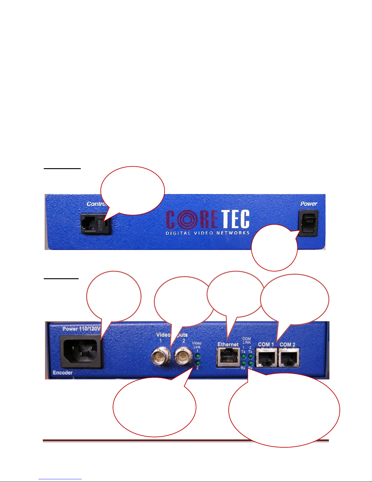
Familiarization with the VCX4402-E......................................................................................... 4
Com Port Data Interface ............................................................................................................. 5
Video Input Interface.................................................................................................................. 5
Ethernet Interface........................................................................................................................ 5
Power .......................................................................................................................................... 5
Display (full size encoder only).................................................................................................. 5
Mounting the Encoder................................................................................................................. 6
Quick Start...................................................................................................................................... 7
If user wishes to configure settings with VCX4402-E via COM Port or Network:................... 7
Updating Firmware with TFTP....................................................................................................... 9
IP Configuration............................................................................................................................ 10
Overview................................................................................................................................... 10
Initial IP Addressing................................................................................................................. 10
Connecting to Unit........................................................................................................................ 12
Program Commands...................................................................................................................... 20
Network Setup .......................................................................................................................... 20
Common Commands ................................................................................................................ 22
Encoder Commands.................................................................................................................. 22
COM Port Setup........................................................................................................................ 23
OSD COMMANDS (On Screen Display)................................................................................ 25
Video Commands...................................................................................................................... 26
SAP Settings ............................................................................................................................. 28
SNMP Settings.......................................................................................................................... 29
Miscellaneous Settings.............................................................................................................. 30
Specifications................................................................................................................................ 32
Model Numbers ............................................................................................................................ 33
Appendix A................................................................................................................................... 34
Pinouts....................................................................................................................................... 34

VCX-4402-E Installation and Operating Instructions Page 3
Com Port Data Interface Pin Out (uses RJ-45 Plug)............................................................. 34
Standard Ethernet Pin Out .................................................................................................... 35
RJ-11 to Serial Interface Adaptor Pinout.............................................................................. 36
Introduction
The model VCX-4402-E is the stand-alone Dual MPEG-4 version of the VCX family and is
housed in a 19-inch 1U rack mount case with a display, control port and a universal AC power
supply. The configuration of the VCX-4402-E-H is akin to desktop like devices being 1U high
but only 8.5 inches wide. The model VCX-4402–E-R is a rack mounted card only used in the 4U
19-inch rack unit. See Accessories R-12.
The VCX Digital Video transport system consists of the video encoder and a decoder. These
will make up an encoder/decoder pair providing the capability for one-way end-end transmission
of the compressed digital video stream in one of two formats. The format is MPEG4 standard
ISO/IEC 14496. The transportation process is performed by transmitting and receiving IP
packets at data rates in the 64 kbps to 4.0 Mbps range. The encoding-decoding process is applied
to an NTSC (or PAL) video input, selected in software.
The video encoder converts the Analog Video to a Serial Digital signal, which is multiplexed
with any data sub-channels present. The stream is then formatted into a series of IP packets sent
to the network through a standard Ethernet connection.
Modification of video format and resolution, data sub-channel characteristics, and basic IP
parameters is achieved through one of the following means:
a) A terminal Program
b) Telnet through the Ethernet connection
c) Watchdog CCS Software
d) SNMP
e) Web Interface
The video decoder receives the IP packets, separates the video data from the data sub-
channels, and converts the video data to analog form, providing an NTSC (or PAL) output.
The units feature two bi-directional data sub-channels (support for RS-232 or RS-422) and a
separate front-panel terminal port. Sub-channel information is removed from the video stream by
the encoder thus completing the control link back to the decoder that is supplying the pan-tilt-
zoom commands.

VCX-4402-E Installation and Operating Instructions Page 4
Familiarization with the VCX4402-E
The VCX-4402-E Video Encoder accepts two BNC video input and two data sub-
channels. The output from the encoder is a stream of IP-packets. The Full Width (19”) Encoder
also contains a fluorescent LED display to allow monitoring of unit performance and to facilitate
troubleshooting.
The VCX-4402-E Video Encoder has a programmable reset, which prompts the re-
initiation of the video stream, as well as a reboot command. The decoder also has a
programmable reset command, tied to errors in the incoming video stream, as well as a reboot
command.
Front Panel
VCX4402-E-H, Half Size Encoder
Back Panel
VCX4402-E-H, Half Size Encoder
Power
switch
-controls the
unit power
Control Port
-Used to directly
communicate with
encoder to configure
settings
Power Supply
Refer to “Power
Interface” in
Table of Contents
2 Video Inputs
Please refer to
“Video Interface” in
table of contents
Ethernet
Refer to “Ethernet
Interface” in Table
of Contents
2 Data Sub-
channels
Refer to “Com Port
Data Interfaces” in
Table of Contents
Com Link
These four (4) LEDs signify the activity
of the communications traffic. When lit
signifies ACTIVITY. There are two
indicators for each channel Tx and Rx. Tx
signifies the encoder is transmitting data
to the connected device. Rx signifies the
encoder is receiving data from the
connected device.
Video Link
These indicators will display
the status of the video signal
and when lit signifies the loss
if the video signal.

VCX-4402-E Installation and Operating Instructions Page 5
Com Port Data Interface
There are two bi-directional data interfaces, RS-232 and RS-422 selectable, on the encoder and
decoder assemblies. Each interface uses RJ-45 connectors. Refer to Table below for the correct pin out.
When using the RS-232 configuration pin 7 is ground. Com Port parameters are configured through the
system software.
Refer to Appendix A for the correct pin out.
Video Input Interface
Connect a BNC-terminated coaxial cable from a composite video source (e.g., CCTV camera) to
the BNC connector labeled “VIDEO IN” (encoder). The composite video input should be in NTSC or
PAL format. The maximum length of cable that should be interfaced to the encoder or decoder is 100 feet,
although the specific installation environment will dictate the actual permissible length.
Ethernet Interface
There is one Ethernet interface for encoder or decoder, which uses a standard RJ-45 connector.
The standard method of terminating an ETHERNET cable reflects the TIA568A standard
(Telecommunications Industry Association standard).
Refer to Appendix A for the Straight Through and Crossover Ethernet Pin Out.
Power
Power is applied through a standard IEC type detachable line cord at the rear of the unit. The unit
automatically senses 110 VAC or 220 VAC supply and will operate with either. The typical current is 1.2
amps from a 110VAC line and drops to .9 amps from a 230 VAC line source.
Display (full size encoder only)
The fluorescent LED display (Full Width 19” Encoder only) provides a scrolling list of key
parameters when the unit is in its active (non-stand-by) state.
The display is a two-line display. Each parameter is displayed, in turn, for three seconds
on the bottom line. It then moves to the top line while the next parameter is displayed on the
bottom line.
The parameters displayed are as follows:
Name of unit
Software version
This manual suits for next models
1
Table of contents
Other Coretec Media Converter manuals
Popular Media Converter manuals by other brands

H&B
H&B TX-100 Installation and instruction manual

Bolin Technology
Bolin Technology D Series user manual

IFM Electronic
IFM Electronic Efector 400 RN30 Series Device manual

GRASS VALLEY
GRASS VALLEY KUDOSPRO ULC2000 user manual

Linear Technology
Linear Technology DC1523A Demo Manual

Lika
Lika ROTAPULS I28 Series quick start guide

Weidmuller
Weidmuller IE-MC-VL Series Hardware installation guide

Optical Systems Design
Optical Systems Design OSD2139 Series Operator's manual

Tema Telecomunicazioni
Tema Telecomunicazioni AD615/S product manual

KTI Networks
KTI Networks KGC-352 Series installation guide

Gira
Gira 0588 Series operating instructions

Lika
Lika SFA-5000-FD user guide