Coretec VCX-7401 User manual

INSTALLATION AND OPERATING INSTRUCTIONS
Revision Date: August 26, 2011
VCX-7401 Dual H.264/MPEG-4 E coder with H.264 Decoder
1
Core Tec Communications, LLC
2950 Lake Emma Rd
uite 1030
Lake Mary, FL 32746 U A
Phone (407) 331-0547
Fax (407) 331 0656
www. coretec.com
Technical upport:
U. . 877-331-0547
(Toll Free)
Elsewhere: 407-331-0547

2

I troductio
The model VCX-7401 is the stand-alone H.264/MPEG4 version of the VCX
family and is housed in a 8.5-inch 1U rack mount case with a control port and a
universal AC power supply.
The VCX Digital Video transport system consists of two video encoders, H.264
and MPEG4, and a decoder. This makes up the encoder(selectable)/decoder pair
providing the capability for one-way end-end transmission of the compressed
digital video stream in the H.264 format. The encoding-decoding process is
applied to an NT C (or PAL) video input, selected in software.
Modification of video format and resolution, data sub-channel characteristics, and
basic IP parameters is achieved through one of the following means:
a) Terminal Program
b) Telnet through the Ethernet connection
c) Web Interface Applet
d) NMP
3
NOTE: The VCX7401 is optimized for encoder or decode operation. While both
the encoders and decoder can be used simultaneously, it is not recommended as
perfomance issues may occur. The exception is using the decoder to view it's
own H.264 stream, as this has minimal affect on performance.

Familiarization with the VCX-7401
The VCX-7401 Video Encoder accepts one BNC video in, one BNC Video Out
and one data sub-channel. The encoder has a programmable reset, which prompts
the re-initiation of the video stream. The decoder also has a programmable reset
command, tied to errors in the incoming video stream, as well as a reboot
command.
Birds Eye view of the VCX-7401
Fro t Pa el
Front view of the VCX-7401
4

Back Pa el
Rear view of the VCX-7401
Com Port ata Interface
There is one bi-directional data interface, R -232 and R -422 selectable, on the encoder,
which uses a RJ-45 connector. Refer to Table below for the correct pin out. When using
the R -232 configuration pin 4 is ground. Com Port parameters are configured through
the system software.
Refer to Appe dix A for the correct pi out.
Video Input Interface
Connect a BNC-terminated coaxial cable from a composite video source (e.g., CCTV
camera) to the BNC connector labeled “VIDEO IN” (encoder). The composite video
input should be in NT C or PAL format. The maximum length of cable that should be
interfaced to the encoder or decoder is 100 feet, although the specific installation
environment will dictate the actual permissible length.
Ethernet Interface
There is one Ethernet interface for encoder or decoder, which uses a standard RJ-45
connector. The standard method of terminating an ETHERNET cable reflects the
TIA568A standard (Telecommunications Industry Association standard).
Refer to Appe dix A for the Straight Through a d Crossover Ether et Pi Out.
Power
Power is applied through a standard IEC type detachable line cord at the rear of the unit.
The unit automatically senses 110 VAC or 220 VAC supply and will operate with either.
5

The typical current is 1.2 amps from a 110VAC line and drops to 0.9 amps from a 230
VAC line source.
Mounting the evice
The VCX-7401 Encoder is a 8.5 inch wide device and provides holes for
mounting onto a chassi. The unit can be mounted in any orientation.
Updating Firmware with TFTP
TFTP is a simple and reliable way of updating the firmware on any device. All that is
required is to have access to a TFTP server which will be used as the host and contain the
update file, which is named vcx7401.tgz.
Via Telnet, enter the following command in order to update the firmware for the device
that is being used.
TFTP < erver IP Address>
IP Configuration
Overview
The commands contained in this section provide the means to configure
critical network, com ports, encoder, and decoder parameters. The user should
consult the factory if specific functions of interest do not appear to be supported.
Initial IP Addressing
To set the device parameters properly, encoder and decoder units must be
given appropriate IP addresses, compatible with the network on which they are to
be connected. The software module VXNETCONFIG was developed to allow a
network administrator to set the IP and ubnet in the VCX-7401.
•Installation
To load VXNETCONFIG insert the CORE TEC CD into your CD drive. elect
VXNETCONFIG by double clicking on the program. The following window will
open:
6

VCXNETCONFIG Wi dow
7

Descriptio of Program Fu ctio s
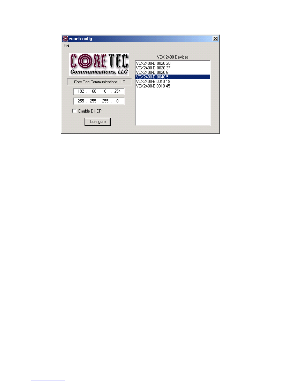
(a) The first box on the left hand side of the window displays the current IP
address of the CORE TEC device being interrogated. Type the new IP
address into this space
(b) The second box is used to change the UBNET address. Note that the address
displayed is always 255.255.255.0. Type the new UBNET address into this
space.
(c) The Enable DHCP box is checked when DHCP is to be enabled.
NOTE: DHCP is ot curre tly e abled o the VCX-7401. Selecti g DHCP
Will have o affect.
NOTE: Do ot e able DHCP if sub-cha els are bei g used of if there is o
DHCP server. Check with the Network Admi istrator, or call Core Tec
Tech Support if further assista ce is eeded.
(d) The Configure button is to execute the requested changes to the IP and
UBNET information. Note that future queries of the UBNET will indicate
255.255.255.0. Therefore, the correct UBNET address should always be
entered prior to using the Configure button.
(e) The box on the right hand of the window displays all VCX-7401 devices
(encoders and decoders) on the network.
(f) To make a cha ge to the equipme t addressi g perform the followi g
steps:
(g) elect the Core Tec device address from the list in the box on the right side of
the window.
(h) Move the cursor to the IP box and select the first octet by highlighting the
octet. Enter the new IP data for the selected octet. As the 3 digits are entered,
the software will automatically highlight the next octet for change. Complete
entering the IP address and then switch to the UBNET data.
(i) Move the cursor to the UBNET box and select the first octet by highlighting
the octet. Enter the new UBNET data for the selected octet. As the 3 digits
are entered, the software will automatically highlight the next octet for
change. Complete entering the UBNET data.
(j) To execute the change press the configure button. The IP address and the
UBNET will be updated in the selected Core Tec equipment. The new IP
8

address will be displayed. The UBNET will display a default class C-
UBNET there is no read back of the changed UBNET displayed.
(k) Repeat this process for all the CORE TEC equipment requiring change.
Connecting to the Unit
There are currently three ways to connect to the VCX-7401.
1. Tel et
Password: admi (default)
To change the default password perform the following:
Type: PASSWORD <followed by your password (up to 11 characters)>
Where <your password> equals the new password.
For configuration using an Ethernet connection, activate the Telnet function by
the following:
•Initiating from the Command Prompt - Telnet nnn.nnn.nnn.nnn
•Use the M Windows – TART – RUN Telnet nnn.nnn.nnn.nnn
(where nnn.nnn.nnn.nnn is the IP address of the unit being configured)
Employ the command set as described below.
Note that the initial IP addresses (factory default) are:
Encoder 192.168.0.253
Decoder 192.168.0.254
ub net Mask 255.255.255.0
2. Termi al Program
NOTE: The following procedure is valid for standalone units only and is not
applicable to rack mount units.
The Terminal Program, such as HyperTerminal, configuration procedure uses the
serial connection on the front of the unit.
9

Using the PCA-2400 programming cable, connect to the control port. This cable
should be attached to the serial port of an attached PC and the Hyper Terminal
program launched. The PC should have its Com Port configured as:
Baud rate 115,200 kbps
Data bits 8 bits
Parity No Parity
top Bits 1 top Bit
Flow control None
Activate the HyperTerminal function, normally found in a sub-menu under
ACCE ORIE . Employ the command set as described in the following section.
Password: admi (default)
To change the default password perform the following:
Type: PASSWORD <followed by your password (up to 11 characters)>
Where <your password> equals the new password
3. Web I terface
To get to the Login Page of the web interface applet, the user needs to type in the
IP adress of the device into a URL. On the Login Page, shown below, the user will
need to type in the password to login successfully.
10

Login Page of Web Interface Applet
When the unit accepts the log in (default password: admin), the following web
page will be displayed.
11

On the top of the screen is a front view image of the device. If you click on any of
these ports the associated tab will appear below the image inside the tabbed pane.
Also an animation will appear for a few seconds on the bottom right corner. The user
may click here in order to to be sent to tutorial page. The user will find here, all the
associated documents to the VCX-7401, such as the manual, as well as video tutorials
on how to use the device and the web applet. Aside from clicking on the ports inteh
image of the device at the top of the applet, they can click directly on the tabs below.
There are currently nine tabs to choose from: Main, Network, ubchannel, O D,
Video, MPEG4, H264, Decoder and Miscallaneous. To the right the user will see 7
buttons: Logout, Commit, Commit/Reboot, Reboot, Open Manual and two other
buttons that allow you to view either the H264 or MPEG4 video stream on a new web
page.
12

Mai Tab
13

Network Tab
14

Subcha el Tab
15

OSD Tab
16

Video Tab
17

MPEG4 Tab
18

H264 Tab
19

Decoder Tab
20
Table of contents
Other Coretec Media Converter manuals