Coretec VCX-6400-D User manual

INSTALLATION AND OPERATING INSTRUCTIONS v1.04
Revision Date: September 1, 2011
VCX-6400-D MPEG-2/4 Decode , IP
VCX-6400-D-R MPEG-2/4 Decode , IP Rack Mount
Core Tec Communications, LLC
2950 Lake Emma Rd
Lake ary, Fl 32746
Phone (407) 331-4724
Fax (407) 331-0656
www.coretec.com
Technical Support:
U.S. 877-331-0547
(Toll Free)

INTRODUCTION .............................................................................................................. 3
DESCRIPTION ....................................................................................................................... 3
STREA FOR ATS ................................................................................................................ 4
BUFFERING .......................................................................................................................... 4
QUICK START .................................................................................................................. 4
ain unit configuration ............................................................................................... 5
Connection Configuration ........................................................................................ 6
PEG2 Configuration ............................................................................................ 6
PEG4 Configuration ............................................................................................. 7
Saving Configuration ............................................................................................... 7
DESK TOP ENCLOSURE (-D ODEL) ...................................................................................... 8
CARD ONLY VIEW (-D-R ODEL) ........................................................................................ 8
COM PORT DATA INTERFACE .................................................................................. 10
CO PORT ........................................................................................................................ 10
CO PORT PIN DESCRIPTION ............................................................................................... 10
RS232 ADAPTER AND CABLE WIRING .................................................................................. 11
VIDEO INTERFACE ...................................................................................................... 11
ETHERNET INTERFACE ............................................................................................. 11
ETHERNET CABLES ............................................................................................................. 11
COMMAND CONTROLS .............................................................................................. 11
UNIT MOUNTING .......................................................................................................... 18
ENCLOSURE OPTIONS .......................................................................................................... 18
DESK TOP ENCLOSURES ...................................................................................................... 18
R-2 ENCLOSURES ............................................................................................................... 18
R-12 ENCLOSURES ............................................................................................................. 18
INTERFACE CONNECTIONS .................................................................................................... 18
POWER ............................................................................................................................ 19
POWER OPTIONS ................................................................................................................ 19
DESK TOP ENCLOSURES ...................................................................................................... 19
R-2 ENCLOSURES ............................................................................................................... 19
R-12 ENCLOSURES ............................................................................................................. 19
FRONT PANEL (VCX6400-D) ....................................................................................... 20
FRONT PANEL .................................................................................................................... 20
Display ....................................................................................................................... 20
Status Indicators ......................................................................................................... 21
Keys ........................................................................................................................... 21
UPDATING FIRMWARE ............................................................................................... 21
PROGRAMMING CONFIGURATION ....................................................................... 22

OVERVIEW ......................................................................................................................... 22
INITIAL IP ADDRESSING ....................................................................................................... 22
CONNECTION ..................................................................................................................... 24
PROGRAM COMMANDS ............................................................................................. 28
CO AND NOTATION ......................................................................................................... 28
CO AND DESCRIPTION ..................................................................................................... 30
Network Setup ........................................................................................................... 30
IP (IP Address) ....................................................................................................... 30
IP ASK (IP Subnet ask) ................................................................................... 31
GATEWAY ............................................................................................................. 32
CLEARGATEWAY ............................................................................................... 32
C DPORT (TCP Command Port) ........................................................................ 32
VIDEOIP (Video Source IP) .................................................................................. 32
VIDEOPORT (Video ulticast Port) .................................................................... 33
CO PORT SETUP ............................................................................................... 33
CO [1|2] (Comm Port Enable) ............................................................................. 35
CO [1|2]BAUD (Comm Port Baud Rate) ............................................................ 35
CO [1|2]PARITY (Comm Port Parity) ................................................................ 35
CO <1|2>STOPBITS <0|1|2> .............................................................................. 36
CO [1|2]IP (Comm Port IP) ................................................................................. 36
CO [1|2]PORT (Comm Port) ............................................................................... 36
CO [1|2]RS422 (RS-232, RS-422 Data Format) ................................................. 37
CO PORT CO AND – FURTHER EXA PLES ..................................... 37
....................................................................................................................................... 38
DECODER CO ANDS ......................................................................................................... 38
Profile ..................................................................................................................... 38
DISPLAY [VIDEO | CO |IP | SAP] .................................................................... 39
CO PRESSION [ PEG2 | PEG4 | JPEG] ....................................................... 39
COMMON COMMANDS ............................................................................................... 40
? or HELP .............................................................................................................. 40
AUTOREBOOT .................................................................................................... 40
AUTOSTART ........................................................................................................ 40
CO IT ............................................................................................................... 41
DEATHBLOW ....................................................................................................... 41
EXIT ...................................................................................................................... 41
NTSC ..................................................................................................................... 42
PAL ........................................................................................................................ 42
REBOOT ................................................................................................................ 42
START ................................................................................................................... 42
STREA TYPE [t|p] .............................................................................................. 42
STOP ...................................................................................................................... 42
VER ........................................................................................................................ 43
TEST PROCEDURES ..................................................................................................... 44
DIRECT CONNECTION VERIFICATION ...................................................................................... 44

INDIRECT (NETWORK) CONNECTION VERIFICATION .................................................................. 44
SPECIFICATIONS .......................................................................................................... 46
PHYSICAL AND ENVIRON ENTAL .......................................................................................... 46
Dimensions ................................................................................................................ 46
Weight ....................................................................................................................... 46
Temperature ............................................................................................................... 46
Humidity .................................................................................................................... 46
POWER REQUIRE ENTS ....................................................................................................... 47
CONNECTORS ..................................................................................................................... 47
Video .......................................................................................................................... 47
Data ............................................................................................................................ 47
ELECTRICAL ................................................................................................................. 47
Video Input (NTSC/PAL) .......................................................................................... 48
Video Output (NTSC/PAL) ........................................................................................ 48
Data (Network) .......................................................................................................... 49
Data (Sub-channels) .................................................................................................. 49
Programming Data ..................................................................................................... 49
PART NUMBERS ............................................................................................................ 51
BASE ODELS ................................................................................................................... 51
ACCESSORIES .................................................................................................................... 52
APPENDIX A ................................................................................................................... 55
UNIT SETUP ...................................................................................................................... 55
APPENDIX B ................................................................................................................... 60
APPENDIX C ................................................................................................................... 61
PINOUTS ............................................................................................................................ 61
Com Port Data Interface Pin Out (uses RJ-45 Plug) .................................................. 61
Standard Ethernet Pin Out ......................................................................................... 62
RJ-11 to Serial Interface Adaptor Pinout ................................................................... 62

Installation and Operating Instructions
VCX-6400-D, VCX-6400-D-R Page 5 of 54

Int oduction
Desc iption
The model VCX-6400-D is the stand-alone PEG-2/4 version of the VCX
family. The unit is enclosed with a display, control keys and a universal AC power
supply. The configuration of the VCX-6400-D is akin to desktop like devices. The
model VCX-6400–D-R is a rack mounted card only used in the 4U 19-inch rack unit.
See Accessories R-12.
The VCX-6400 Digital Video Codec system consists of a video decoder model
VCX-6400-D or –D-R and encoder models VCX-2400-E/-ER or 4400-E/–E-R and the
VCX-6400-E/-ER. Note: the VCX-4400-E and VCX-6400-D units are compatible when
using PEG4 video streams and the VCX-2400-E and VCX-6400-D units are
compatible when using PEG2. When connected with the fore mentioned
decoder/encoder configurations, these units provide a one-way end-end transmission of
compressed digital video. The transmission medium is Ethernet using IP protocol with
data rates in the 64kbps to 4.0 bps range.
The VCX-6400 system employs either PEG-2 or 4 decoding. The encoding-
decoding process is applied to an NTSC (or PAL) video input and output respectively,
selected through software. The VCX-6400 is a decoder only and therefore will decode
both PEG-2 and PEG-4 streams present on the network. (See appendix for details)
The VCX-6400 family supports several stream types through the ethernet
transmission medium. Elementary, PES, Transport, and Program stream types are
supported by the VCX-6400 family in the PEG-2 mode and Elementary Stream (ES) in
the PEG-4 mode.
The video decoder separates PEG video and sub-channel information from the
IP stream. Video is converted to NTSC (or PAL) signal and sent to the BNC connector
while the de-multiplexed sub-channel is passed to the port labeled Com2. Note: Com1
port is for diagnostic purposes by the manufacturer.”
odification of video format and resolution, data sub-channel characteristics, and
basic IP parameters is achieved through one of the following means:
a) a Hyper Terminal accessible menu
b) Telnet through the Ethernet connection
c) S software
d) SN P
e) Web Interface (Only for VCX6400Encoder/Decoder)
The video decoder receives IP packets and separates the video data from the stream. The
decoder then converts the video data to analog form, providing an NTSC (or PAL)
output. The preprogrammed formats are needed in applications providing the sub channel
information, which is passed to the camera control.
Installation and Operating Instructions
VCX-6400-D, VCX-6400-D-R Page 6 of 54

The unit features a bi-directional sub-channel port (programmable for RS-232
or RS-422). Configuration, control, status and other data are de-multiplexed from the
digital data stream, maintaining the communications link with the device connected to
the sub-channel port.
St eam Fo mats
Elementary Stream (ES) is a video elementary stream that consists of all the video
data for a sequence, including the sequence header and all the subparts of a sequence. An
ES stream carries only one type of data (video or audio) from a single video or audio
encoder.
Packetized Elementary Stream is a Packetized Elementary Stream, or PES,
consists of a single ES stream, which has been made into packets, each starting with an
added packet header. A PES stream contains only one type of data from one source, e.g.
from one video or audio encoder.
Transport Stream is a format specified in PEG-2 Part 1, Systems (ISO/IEC
standard 13818-1). Its design goal is to allow multiplexing of digital video and audio and
to synchronize the output. Transport stream offers features for error correction for
transportation over unreliable media.
Program Stream is a format that supports command controls in which the video
stream may be controlled during playback or authoring of video recording. The program
elements are used the playback of a recorded stream.
Buffe ing
Stream buffering gives the decoder the ability to store the incoming stream until a
level is reached that insures the network latency has a minimal effect on the decoded
video. This means the network latency will be hidden to the limit of the buffer to supply
stored data to the decoder. The buffer size is 1 megabyte of storage or 8 megabits of the
incoming data. The latency is measured in milliseconds; therefore, the amount of storage
needed is directly related to the worst-case network delay. The default buffer-low size has
a latency of 100msec and 400msec for the buffer high. Remember this value is viewed as
a time based function related to the incoming bit rate in msec by the network latency in
msec. When the buffer level drops below the buffer, low value the video decoding is
slowed down and when the buffer high value is exceeded, the video decoding is sped up.
This is performed at in imperceptible rate. The minimum value is what the operator is
willing to use for the display quality and the maximum is derived from the following
equation.
6,400,000/Bitrate (Kbps) is the maximum value for the bufferhigh parameter
Generally, set the bufferlow value of 300 less than the bufferhigh number calculated
using the above equation.
Installation and Operating Instructions
VCX-6400-D, VCX-6400-D-R Page 7 of 54

Quick Sta t
The quick start procedure will provide an out of the box startup. The steps in the
procedures that follow may require the assistance of the network administrator. It is not
advisable to connect a default configured unit or a unit with an unknown configuration to
an operational network.
1. Unpack the VCX-6400-D Video Decoder.
2. Connect a BNC-terminated coaxial cable to a composite NTSC (or PAL)
video output (e.g., CCTV monitor) to the BNC connector labeled “VIDEO OUT”
on the VCX-6400-D Video Decoder.
3. Connect a BNC-terminated coaxial cable from a composite NTSC (or PAL)
video source (e.g., CCTV camera) to the BNC connector labeled “VIDEO IN” on
the video encoder. Any of the VCX-2400/4400 PEG2/ PEG4 encoded video
streams on the network may be used if the source video is set on the decoder
VIDEOIP. (See Appendix A Unit Setup)
4. Connect the video encoder to the VCX-6400-D video decoder via the Ethernet
port (RJ-45), located to the right of the two RJ-45 ports on the rear of each unit,
using a Cat 5 Ethernet cross over cable (for direct connection), if a switch is not
available (the send and receive pairs are swapped end-to end). These cables are
identified with a Yellow or Red cover on the connectors. When units are
connected to an Ethernet Switch, straight through cables are used.
Please efe to Appendix C to view the St aight Th ough and C ossove
Ethe net Configu ations.
5. Insert the detachable line cord into the receptacle on the rear of the encoder
and VCX-6400-D decoder. The unit will automatically sense line voltage and
frequency in the range of 110 to 220VAC, 50 or 60 hertz and will function
correctly.
6. The power control is a rocker switch next to the line cord on the back of the
units. The power LED on the front panel display will be illuminated when the unit
is activated.
7. After booting up, the display (if on the decoder) will scroll through the
parameters currently programmed in the unit.
8. After a few moments, video should appear on the output of the VCX-6400-D
Video Decoder.
9. If video is not present on the VCX-6400-D decoder verify the following:
Installation and Operating Instructions
VCX-6400-D, VCX-6400-D-R Page 8 of 54

a. Verify the video source is functioning and supplying a proper video
signal to the encoder.
b. Both the encoder and decoder power LED’s are on. Displays are
scrolling on both units and the Video and ulticast LED’s are “Green”. If the
LED’s are Red then check the “VIDEOIP” address is the same as the source
encoder “VIDEOIP” address. The default video IP address is 239.5.6.8 by
default and a standard cross over cable will function properly.
c. The link light (Green) on the Ethernet port (RJ-45), located on the
lower left of the port connector is lit on both the encoder and decoder. If not
the Ethernet cross over cable may be defective. If data traffic is present the
activity light (Yellow) will be on steady or flashing
d. If the above are correct, please read the network setup installation
instructions in the manual. Note: the setting in default network setup may
have been changed.
Main unit configuration
The VCX-6400-D units incorporate support for two different forms of decoding.
It is important the operator understand this to be able to configure the unit properly. All
commands follow this simple format:
(command<space>parameter<enter>)
From the command prompt, the operator may view the current configuration by
entering the “display” command. This will dump the entire configuration status for the
selected decoder. Take note the IP address must be of valid encoders on the network. The
IP addressed are an example only. Locate a PEG2 or PEG4 encoder to be used.
The compression command will set the decoding format for the output of the unit.
Connection Configu ation
ip 192.168.5.150 (use a valid IP on your network)
mask 255.255.240.0
name CoreTec Decoder
com1 1
com1ip 192.168.5.151 (IP address of the encoder receiving sub-channel commands)
com1tcp 1 (assume a universal decoder)
com1server 0
com1timeout 10
com1baud 38400
MPEG2 Configu ation
The PEG2 encoder requires the following parameters be configured to your network:
compression mpeg2
streamtype p
videoip 239.5.5.150 (use a valid IP on your network)
port 4568 (use the video port number programmed in the encoder)
Installation and Operating Instructions
VCX-6400-D, VCX-6400-D-R Page 9 of 54

MPEG4 Configu ation
The PEG2 encoder requires the following parameters be configured to your network:
compression mpeg4
streamtype rtp
ip 239.5.5.151 (use a valid IP on your network)
port 4568 (use the video port number programmed in the encoder)
Note: the compression type is mpeg2 or mpeg4. The operator will configure the unit for
one or the other.
Saving Configu ation
When all the configuration parameters have been entered, they must be saved to memory
and the unit restarted by entering the following command:
commit
reboot
Installation and Operating Instructions
VCX-6400-D, VCX-6400-D-R Page 10 of 54

VCX Video Decoder Family
The VCX-6400-D Video Decoder will supply a video channel out and one bi-
directional serial data sub-channel. The output from the decoder is a video stream
assembled from received IP packets from the Ethernet port. The unit also contains a
display (available on the VCX-6400-D only) to allow monitoring of unit performance and
to facilitate troubleshooting. The decoder has a programmable reset, which prompts the
re-initiation of the video stream.
The VCX-6400-D Video Decoder accepts the signal from the network originally
generated by a VCX-2400/4400-E video encoder family member. The unit effectively
decompresses this data stream and re-creates an analog waveform in NTSC (or PAL)
video format. The unit supports one bi-directional serial data port sub-channel,
functioning as RS232/RS422. The VCX-6400/6400-D and the -D–R models use the same
control board whereas the –D-R is a rack mounted card only; while, the –D is enclosed
with a power supply and front panel.
Desk Top Enclosu e (-D Model)
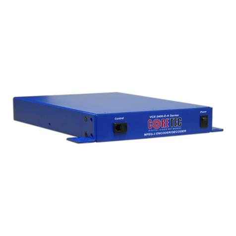
Figu e 3 – VCX-6400-D F ont View
Installation and Operating Instructions
VCX-6400-D, VCX-6400-D-R Page 11 of 54

Figu e 4 – VCX-6400-D Back View
Ca d Only View (-D-R Model)
Figu e 5 – VCX-6400-D-R
Installation and Operating Instructions
VCX-6400-D, VCX-6400-D-R Page 12 of 54

COM Po t Data Inte face
Com Po t
1.
2. There are two bi-directional data interfaces on the VCX series
units; each may be configurable for either RS-2 2 or RS-422 through
software. Com2 is the sub-channel port (center) while Com1 is for testing
only (Left most). Refer to Table 1 for the correct pin out. Comm Port
parameters are configured through the system software.
Com Po t Pin Desc iption
The 8-pin RJ45 connector supports both RS232 and RS422 standards. Take note
of the pin out for the proper PC interface if used. An adaptor is available from the
manufacturer that performs a conversion supporting one-to-one ethernet cables as the
connection media to the PC 9-pin D-sub connector. RS422 is also supported with a
different wiring configuration.
Please efe to Appendix A fo Com Po t Data Inte face pinout.
Installation and Operating Instructions
VCX-6400-D, VCX-6400-D-R Page 13 of 54

RS232 Adapte and Cable Wi ing
The user may build an RS232 cable fashioned from a one-to-one ethernet cable. A
drawing of the cable and the manufacturer-supplied adapter are shown below.
Please efe to Appendix C to view RJ-11 to Se ial Inte face Adapte Pinout.
Video Inte face
3. Decoded and assembled video, in the NTSC or PAL format, is
supplied out the BNC connector in the back of the unit. Connect a BNC-
terminated coaxial cable from a composite video monitor to the BNC
connector labeled “VIDEO OUT” (decoder). The maximum length of
cable that should be interfaced to the decoder is 100 feet, although the
specific installation environment will dictate the actual permissible length
and proper termination.
4.
Ethe net Inte face
There is one Ethernet interface for encoder or decoder, which uses a standard RJ-
45 connector located to the far right side of the back panel.
Note: the Ethernet port is the larger of the RJ45 connectors and has two status
LED’s at the bottom. Refer to Figure 3 for the correct pin out.
Ethe net Cables
The standard method of terminating an ETHERNET cable is shown in Figure 6.
Figure 8 reflects the TIA568A standard (Telecommunications Industry Association
standard). The cable types support the Hub/Switch connections, which are the standard
one for one wire connection though out the cable. These cables may be of different colors
and lengths; but will have the same color connector cover, if present, as the cable color.
If the cable is a crossover type, the cable color will be RED with a YELLOW or
RED connector cover. If the switch is AUTO DETECT, the crossover cable will function
as a standard cable and the user will be unaware of the cable. If non-auto detect devices
are connected in this way, communications will not take occur.
NOTE: The crossover identification standard, at times, is not followed.
Verification may be performed by following the description and diagrams below.
The solid color wires and the striped wires (color stripe on white wire) are always
alternated across the connector pins. Pin-1, always being striped, in the diagram below, is
White/ORANGE followed by solid ORANGE on pin-2 as the second in the pair. Take
note of pin-3, as it is not paired with pin 4, but with pin-6. In the diagram pin-3, being
White/GREEN and pin-6 is solid GREEN. Next is pair number one, solid BLUE on pin-4
Installation and Operating Instructions
VCX-6400-D, VCX-6400-D-R Page 14 of 54

and White/BLUE pin-5, these are always in the middle of the connector. Followed by
White/BROWN on pin-7 and solid BROWN on pin-8.
Command Cont ols
To give a command to the encoder you have alternative ways of doing so:
1) TelNet through the Ethernet connection
2) Hyper Terminal accessible menu
3) Web Interface
4) S software
5) SN P (only for VCX6400E/D)
Telnet
Refer to the Program Commands Section of this anual below for the specific
commands.
Default Password: admin
This password may be changed by typing in the following command:
PASSWORD [new passw rd f y ur ch ice]
Hype Te minal
You may also configure settings via Hyper Terminal if the serial port is connected to the
decoder.
Web Inte face
When the unit accepts the log in (default password: admin), the following web
page will be displayed. The header identifies the type of unit followed by the page control
bar. The basic network configuration is displayed in the appropriate fields giving the
operator the option to modify them if needed. There are three (3) pages to select from
each giving the operator control over the unit operation. ain, Video, Subchannel
provide all the parameters that an operator may modify grouped as labeled. There are two
(2) options to the far right, “Log Out” and “Commit/Reboot”, which will terminate the
session. Log Out will log the operator out without committing to the changes made in the
previous pages and the last will perform the commit function, writing the changes to the
unit and performing a reboot. Both operations will log the operator off and close the
communications channel. The web page may or may not report the termination of the
communications channel. The login process must be performed to access the unit again.
Installation and Operating Instructions
VCX-6400-D, VCX-6400-D-R Page 15 of 54

The follow pictures show the various parameters available to the operator. The
definitions are described below in the command sections.
Installation and Operating Instructions
VCX-6400-D, VCX-6400-D-R Page 16 of 54

Open a new Internet Explorer window and enter the IP address of the unit into the
explorer address frame. (Review the section INITIAL IP ADDRESSING to obtain this
address.
The selected device will respond by opening the following page. Not all internet
communication pages will apply while the thread is open.
Log on Page
Type password XXXXXXXXXXX
Where XXXXXXXXXXX is the new password.
The password can be anything up to eleven (11) characters in length.
Installation and Operating Instructions
VCX-6400-D, VCX-6400-D-R Page 17 of 54

Main Page- Configuration Parameters
Video- Configuration Parameters
Installation and Operating Instructions
VCX-6400-D, VCX-6400-D-R Page 18 of 54

Subchannel- Configuration Parameters
Logout
You must commit and reboot (button to the right) in order to save the new settings made
during this session.
Installation and Operating Instructions
VCX-6400-D, VCX-6400-D-R Page 19 of 54

Commit/Reboot
This process will write all the parameters into nonvolatile memory and then reboot the
unit. The reboot process will stop all current operations and restart with the new
parameters.
Note: The Commit/Reboot operation, in most cases, will not give the operator an
indication the operation has started, is in progress or has finished.
MMS Softwa e
Refer to the Watchdog anuals
SNMP
SN P is available if wanted.
The two (2) .mib files are available at our website (www.coretec.com). A password will
be needed to access these files.
Installation and Operating Instructions
VCX-6400-D, VCX-6400-D-R Page 20 of 54
This manual suits for next models
1
Table of contents
Other Coretec Media Converter manuals