Coretec VCX-4400-E User manual

INSTALLATION AND OPERATING INSTRUCTIONS
Revision Date: March 3, 2010
VCX-4400-E MPEG-4 Encoder, IP
VCX-4400-ER MPEG-4 Encoder, IP Rack Mount
Core Tec Communications, LLC
2950 Lake Emma Rd
Suite 1030
Lake Mary, FL 32746 USA
Phone (407) 331-0547
Fax (407) 331 0656
www.coretec.com
Technical Support:
U.S. 877-331-0547
(Toll Free)
Elsewhere: 407-331-0547

TableofContents
Introduction..................................................................................................................................... 3
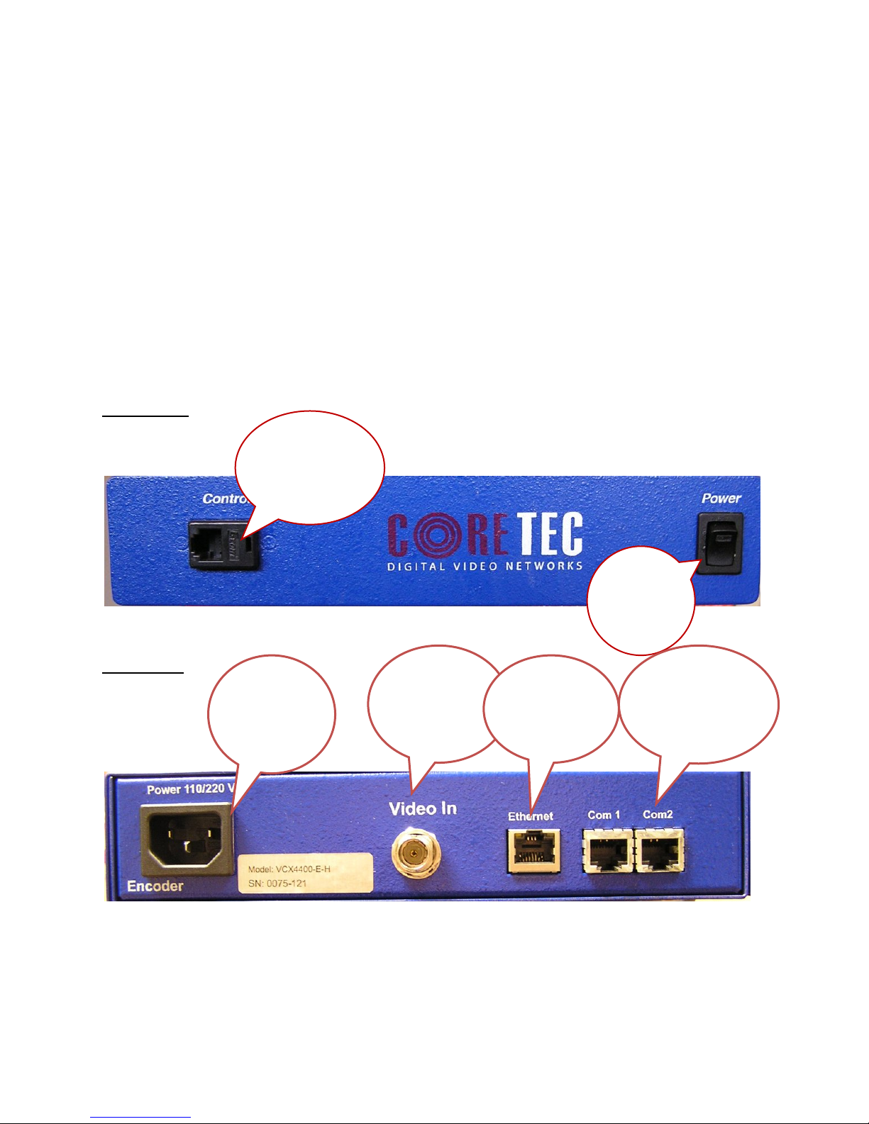
Familiarization with the VCX4400-E......................................................................................... 4
Com Port Data Interface ............................................................................................................. 5
Video Input Interface.................................................................................................................. 5
Ethernet Interface........................................................................................................................ 5
Power .......................................................................................................................................... 5
Display........................................................................................................................................ 5
Mounting the Encoder................................................................................................................. 6
Quick Start...................................................................................................................................... 6
If user wishes to configure settings with VCX4400-E via COM Port or Network:................... 6
Updating Firmware with VCXNetBurner....................................................................................... 8
IP Configuration............................................................................................................................ 18
Overview................................................................................................................................... 18
Initial IP Addressing................................................................................................................. 19
Connecting to Unit........................................................................................................................ 21
Program Commands...................................................................................................................... 23
Network Setup .......................................................................................................................... 23
Common Commands ................................................................................................................ 24
Encoder Commands.................................................................................................................. 25
COM Port Setup........................................................................................................................ 25
OSD COMMANDS (On Screen Display)................................................................................ 28
Video Commands...................................................................................................................... 28
SAP Settings ............................................................................................................................. 30
Miscellaneous Settings.............................................................................................................. 32
Specifications................................................................................................................................ 33
Model Numbers ............................................................................................................................ 35
Appendix A................................................................................................................................... 36
Pinouts....................................................................................................................................... 36
Com Port Data Interface Pin Out (uses RJ-45 Plug)............................................................. 36
Standard Ethernet Pin Out .................................................................................................... 36
RJ-11 to Serial Interface Adaptor Pinout.............................................................................. 37
Troubleshooting........................................................................................................................ 38

Introduction
The VCX-4400-E and the -ER are the chassis versions of the Core Tec stand-alone VCX-
4400 MPEG-4 IP product series. These units are fully compatible with the “-ER” card cage
versions of the product series.
The VCX-4400 Digital Video Codec system consists of a video encoder and a Core Tec
decoder pair providing the capability for one-way end-end transmission of compressed digital
video in IP packets at data rates in the 64kbps to 3.5 Mbps range.
The system employs MPEG-4 encoding. The encoding-decoding process is applied to an
NTSC (or PAL) video input, selected in software.
The video encoder converts the video to a serial signal, which is multiplexed with any
data sub-channels present. The stream is then formatted into a series of IP packets sent to the
network through a standard Ethernet connection.
Modification to video format and resolution, data sub-channel characteristics, and basic
IP parameters are achieved through one of the following means:
a) a Hyper Terminal accessible menu
b) Telnet through the Ethernet connection
c) Watchdog CCS
The video decoder receives the IP packets, separates the video data from the data sub-
channels, and converts the video data to analog form, providing an NTSC (or PAL) output.
The units feature two bi-directional data sub-channels (programmable for RS-232 or RS-
422). Data bits are multiplexed with the digital data stream.

FamiliarizationwiththeVCX4400E
The VCX-4400-E Video Encoder accepts one video and two data signals. The output
from the encoder is a stream of IP- packets. It also contains a fluorescent LED display to allow
monitoring of unit performance and to facilitate troubleshooting. The encoder has a
programmable reset, which prompts the re-initiation of the video stream as well as a reboot
command.
The VCX-4400-D Video Decoder accepts the signal from the network originally generated by a
VCX-4400-E video encoder. The unit effectively decompresses this data stream and re-creates
an analog waveform in NTSC (or PAL) video format. The unit supports the bi-directional data
transmission of two data sub-channels, corresponding to the encoder. The unit also features an
LED display. The decoder also has a programmable reset command, tied to errors in the
incoming video stream, as well as a reboot command.
Front Panel
VCX4400-E-H, Half Size Encoder
Back Panel
VCX4400-E-H, Half Size Encoder
Power
switch
-controls the
unit power
Control Port
-Used to directly
communicate with
encoder to configure
settings
Power Supply
Refer to “Power
Interface” in
Table of Contents
Video Input
Refer to “Video
Interface” in table of
contents
Ethernet
Refer to “Ethernet
Interface” in Table
of Contents
2 Data Sub-
channels
Refer to “Com Port
Data Interfaces” in
Table of Contents

ComPortDataInterface
There are two bi-directional data interfaces, RS-232 and RS-422 selectable, on the encoder and
decoder assemblies. Each interface uses RJ-45 connectors. Refer to Table below for the correct pin out.
When using the RS-232 configuration pin 7 is ground. Com Port parameters are configured through the
system software.
Refer to Appendix A for the correct pin out.
VideoInputInterface
Connect a BNC-terminated coaxial cable from a composite video source (e.g., CCTV camera) to
the BNC connector labeled “VIDEO IN” (encoder). The composite video input should be in NTSC or
PAL format. The maximum length of cable that should be interfaced to the encoder or decoder is 100 feet,
although the specific installation environment will dictate the actual permissible length.
EthernetInterface
There is one Ethernet interface for encoder or decoder, which uses a standard RJ-45 connector.
The standard method of terminating an ETHERNET cable reflects the TIA568A standard
(Telecommunications Industry Association standard).
Refer to Appendix A for the Straight Through and Crossover Ethernet Pin Out.
Power
Power is applied through a standard IEC type detachable line cord at the rear of the unit. The unit
automatically senses 110 VAC or 220 VAC supply and will operate with either. The typical current is 1.2
amps from a 110VAC line and drops to .9 amps from a 230 VAC line source.
Display
The fluorescent LED display (Full Width 19” Encoder only) provides a scrolling list of key
parameters when the unit is in its active (non-stand-by) state.
The display is a two-line display. Each parameter is displayed, in turn, for three seconds
on the bottom line. It then moves to the top line while the next parameter is displayed on the
bottom line.
The parameters displayed are as follows:
Name of unit
Software version
Device IP address
Sub-net mask

Video IP (multi-cast group)
Group Length
FPS (frames per second)
Maximum Bit Rate (encoder only)
Audio On or Off
Com 1 On or Off
Com 1 Bit Rate
Com 1 IP
Com 2 On or Off
Com 2 Bit Rate
Com 2 IP
MountingtheEncoder
The VCX-4400-E Encoder is a 19-inch wide 1U unit and is furnished with mounting ears
allowing installation in a 19” rack frame. The VCX-4400-E-H is a desktop like unit that is 8.5
inches wide and designed to be a shelf model without the need to mounting. However if you
choose to mount the half size model, extended mounting ears are available. The VCX-4400-E-R
is a single card for use in the multi-card chassis, which is a 19-inch 4U unit that will support 12
cards.
All signal connections are from the rear, eliminating any need for setback from the front
plane of the rack. The user programming port on the front panel is used to alter system
parameters via a Terminal Program such as HyperTerminal.
QuickStart
IfuserwishestoconfiguresettingswithVCX4400EviaCOMPortorNetwork:
Set up for COM Port:
User may configure VCX4400-E setting using a PC connected to the encoder
control port at the front of the unit. A simple 6-wire phone cable (PCA-2400
programming cable) with the RJ-11 adaptor described in Appendix A will supply the
proper RS-232 connection to the PC’s serial port. Note: This is not the same as the “Sub-
Channel” interface. Do not use the RJ-11 adaptor for this channel.
This configuration will permit the unit configuration by a terminal program running on a
PC. Once you have connected the encoder to the PC’s serial port open your terminal
program. The encoder will boot up then ask for a password. The default password is:
admin.
The PC should have its Com Port configured as:

Baud rate 38,400 kbps
Data bits 8 bits
Parity No Parity
Stop Bits 1 Stop Bit
Flow control None
Refer to Appendix A for pin layout for RJ-11 connector.
Set up for network:
If the operator wishes to configure the unit through the network the user may
accomplish this by the following procedure. Note: The operator must be sure that the
VCX-4400-E is accessible on their SUBNET. Before completing this step, please refer
to the Programming Configuration Section of this Manual. Here you will set the IP
address and SUBNET Mask of the VCX-4400-E so that it is accessible on your SUBNET
and has a valid IP address. (An example IP address is being used in the following
example.):
Open a “cmd” window and enter the following commands:
Telnet192.168.0.253 <enter>
The encoder will reply asking for a password. Default password is “admin”.
Password: admin
Having used either of these methods, the encoder is ready to receive configuration
commands.
Main unit configuration
The VCX-4400-E units incorporate support for one form of encoding from two different input
channels. It is important the operator understand this to be able to configure the unit properly. All
commands follow this simple format:
(command<space>parameter<enter>)
From the command prompt, the operator may view the current configuration by entering the
“display” command. This will dump the entire configuration status for the selected encoder. Remember
there are two encoders in one unit. Enter the following configuration for each of the encoder channels.
Take note the IP address must be of valid encoders on the network. The IP addresses below are just used
as an example. Locate an MPEG4 encoder.
Connection Configuration
ip 192.168.5.150 (use a valid IP on your network)
ipmask 255.255.240.0
name CoreTec Encoder
com1 1

com1ip 192.168.5.151 (IP address of the decoder that is sending sub-channel commands)
com1tcp 1 (assume a universal decoder)
com1server 0
com1timeout 10
com1baud 38400
MPEG4 Configuration
The MPEG4 encoder requires the following parameters be configured to your network:
videoip 239.5.5.151 (use a valid IP on your network)
port 4570
bitrate 1000
res cif
fps 15
Saving Configuration
When all the configuration parameters have been entered, they must be saved to memory and the unit
restarted by entering the following command:
Commit<enter> (please wait a moment until the following prompt appears:)
COMMIT
DONE
Reboot<enter>
UpdatingFirmwarewithVCXNetBurner
Introduction
VcxNetburner is a Windows 2000/XP application that allows updating of the VCX-2400
Encoder/Decoder firmware (as well as the VCX4400E and VCX6400E.) VcxNetBurner can
simultaneously the firmware of all VCX-2400 devices that can be accessed on your network. If
you can telnet to the device then VcxNetBurner can update the firmware. The only exception is
that the device’s current firmware version must be v1.5 or higher. Firmware v1.4 does not
contain the update feature.

Overview
VcxNetBurner has a few interface features that the user should be familiar with before
attempting to update a device. The basic steps are… 1) import the firmware description, 2)
broadcast the server IP, and then 3) initiate the update. However the user needs to be aware of
the general process, optional steps, potential problems, and what to do in the case of an error. We
will start with an overview of the user interface.
Screens
The Activity Screen

The Activity screen contains a list of the current activity and a history of past update operations.
A VCX-2400 device that has finished updating with indicate either 1) Complete, 2) Version
Current, or 3) Failed. The Device column lists the serial number of each unit that is responding
to the update command.

NOTE: It is important that a VCX-2400 device that has a Failed status NOT be turned off or
rebooted. At the point that the failure occurs the device will not be in a bootable state. If power is
cycled or the firmware cannot be updated without failure after repeated attempts then the
firmware chip will need to be replaced. The 10Mbps revision 2.5 devices (in current production)
have removable chips that can be replaced in the field. The 100Mbps revision 3.0 devices must
be reprogrammed at the factory. Since revision 3.0 is not yet in production there may be other
safeguards, such as automatic firmware backup that may modify these instructions.
When a device is in the process of upgrading, the Activity screen will show the progress as a
percent of complete for each stage. There are four stages.. 1) Erasing, 2) Startup Code, 3)
Application Code, and 4) FPGA. When erasing the progress may not update but erasure will
compete in a few seconds. The startup code frequently completes so quickly that you don’t see it
in the Status column.
After the FPGA status reaches completion you should see the Status column change to
Complete. If it changes to Failed at any time during the firmware update you will need to retry
updating the firmware for that unit before cycling power or rebooting.
The Clear Complete button will clear the list display of any operations that did not fail. The
Clear Failed button will clear the list display of any failed operations. The Initiate Update will
Broadcast a command to all online units to connect to the update server to perform a firmware
update. Normally the update server will be the computer that is running VcxNetBurner. However
it would be possible to have VCX-2400 devices configured to use a different server. When
Initiate Update is pressed, all of the VCX-2400 devices within range of multicast packets will
connect to its preset update server.
VCX2400D Screen
The VCX2400D is accessed through the VCX-2400D tab and displays the parameters used to
select the version of the firmware sent to VCX-2400 decoder devices. This information is
imported from a import.ini file that is provided with each firmware update. This screen allows
the operator to see what update is selected. It is important to confirm that the files indicated in
the file selection boxes are located on your computer. The import file is selected using the

menu’s File- >Import option. This is explained later in this document. The Apply button saves
the current setting on this screen so that when VcxNetBurner is loaded these parameters are
restored. The Revert button will reload the currently saved parameter set. So if you have
modified this screen it can be restored if you haven’t used apply.
The Encoder Screens- VCX2400E, VCX440E, & VCX6400E (2/4/J-E)
The Encoder screens are accessed through the VCX2400E, VCX440E, & 2/4/J-E tabs and work
identically the same as the VCX-2400D, except that the parameters are applied to the firmware
sent to the VCX-2400, 4400, or 2/4/J Encoder devices.


The Menu
File Menu
The menu contains selections for 1) File, 2) Options, and 3) Help. The File menu selection
presents the following drop down menu:
The Exit option will close the application. The Import selection is used to select and configure
VcxNetBurner for a particular firmware update version. Each firmware update will come with an
import.ini file that contains the necessary information and is accessed though the Import menu
selection. The import files are normally separate for both the decoder and encoder, and the
supplied updates should each be stored in a unique directory so that the various update files are
not overwritten. When the operator selects Import, a file selection dialog will be presented. The
operator should navigate to the directory were the firmware update is located and the import.ini
file well be selected by default as shown in the following picture:
After pressing the Open button the following dialog will be displayed.

This dialog is telling you that you can save the imported parameters by pressing OK. Or by
pressing Cancel just use the parameters until the application is closed. If you press Cancel the
parameters are still loaded but the old parameters will be loaded then next time VcxNetBurner is
used. Selecting OK is the same as selecting Cancel and then Apply.
NOTE: If you have both encoder and decoder devices you will need to perform the Import
operation twice. One import should be performed for each type of device.
Options Menu
The Options menu selection will provide the following dropdown menu.
There are five selections in the Options menu… 1) Ignore Version, 2) Broadcast Server, 3) Lock
Update 4) Perform Packet Test & 5) Write CTC File.
The Ignore Version selection toggles between on and off. It normally should not be checked. It
will cause a device to update using the current parameters regardless of the current version. It
can be used to change a device to an older version, or even re-update the current version.
Devices will normally update only if the current device firmware version is less than the version
listed in VcxNetBurner. For example if the current device firmware version is 1.5a and the new
version is 1.5a or below, an update command will return the status “Version Current”. See the
Activity screen in this document for an example. If the Ignore Version selection is checked then
you will never get a “Version Current” status.
The second option is Broadcast Server. When the operator makes this selection it causes

VcxNetBurner to multicast a command to all devices to set their Update Server IP to the
computer running VcxNetBurner. The devices will only remember the Update Server IP until the
next reboot or power cycle. Reboots automatically occur after a successful firmware update. It is
not necessary to perform a Broadcast Server operation if the devices have already been
programmed with an Update Server IP. This can be done with Telnet using the command:
UPDATEIP xxx.xxx.xxx.xxx
It is also possible to configure a device to use a hostname (or URL) to address the server if a
DNS server is also configured. The following are example Telnet commands for this operation.
UPDATENAME www.myupdateserver.com
DNSIP xxx.xxx.xxx.xxx
However, unless you have specific reasons for setting up your update server in the device, the
Broadcast Server command will suffice for updating your VCX-2400 device.
The Lock Update allows you to update all VCX-Devices of one type (i.e.- all VCX-2400E
connected to the network) simultaneously. We do not recommend this if you are just beginning
to use the software, due to the risk of overlooking a failure of one particular device.
Rather than this, it is suggested to update only one device at a time. This is done by following the
first 6 steps of the instructions listed above and then Telnet into the unit you wish to update and
issue the following command:
UPDATEFIRMWARE
OR
UF
You should monitor the Activity screen for progress. The Telnet session will also provide some
text display that indicates completion. If the operation is successful then the device will
automatically reboot and the Telnet session will be dropped. If the operation failed then you
should retry the UPDATEFIRMWARE command.
TIPS: If using Telnet, use the DISPLAY IP command to verify that an update server IP is listed.
Also ensure that the update server IP is reachable. This would be true if the update server is the
same as the computer in the Telnet session.
The Perform Packet Tests tests to see if the firmware can be downloaded successfully without
actually being burnt into the unit.
The Write CTC File is for Coretecs internal use only.
Help Menu

The Help menu selection will present the following dropdown menu.
At this time the only option is the About box selection. The about box will display the current
version of VcxNetConfigure. The current version in this example is V1.1 as shown.
Instructions for Use
The following steps should be performed to update your VCX-2400 devices.
1) Obtain the latest update from Core Tec Communications.
2) Place the updates into unique directories for each the decoder and encoder. The
updates will be provided on the FTP server in separate directories.
3) Use the Import menu command to load each update’s import.ini file and use the OK
button to save the current setting.
4) Go to both the Encoder and Decoder screens and verify that the file directories and
version match the latest desired update.
5) Select the Activity screen so that the update process status can be viewed.
6) Use the menu option Options->Broadcast Server to set the current update server to
your computer (optional if configured in the devices).
7) Press the Initiate Update button to multicast the update command to all devices.
8) Monitor the update process on the Activity screen to verify that all units have updated
successfully.
IPConfiguration
Overview
The commands contained in this section provide the means to configure critical network,
com ports, encoder, and decoder parameters. The user should consult the factory if specific
functions of interest do not appear to be supported.

InitialIPAddressing
To set the device parameters properly, encoder and decoder units must be given appropriate
IP addresses, compatible with the network on which they are to be connected. The software
module VXNETCONFIG was developed to allow a network administrator to set the IP and
Subnet in the VCX-4400 series encoders and decoders.
1) Installation
To load VXNETCONFIG insert the CORE TEC CD into your CD drive. Select
VXNETCONFIG by double clicking on the program. The following window will open:
VCXNETCONFIG Window

Description of Program Functions
(a) The first box on the left hand side of the window displays the current IP address
of the CORE TEC device being interrogated. Type the new IP address into this
space
(b) The second box is used to change the SUBNET address. Note that the address
displayed is always 255.255.255.0. Type the new SUBNET address into this
space.
(c) The Enable DHCP box is checked when DHCP is to be enabled.
NOTE: Do not enable DHCP if sub-channels are being used of if there is no
DHCP server. Check with the Network Administrator, or call Core Tec
Tech Support if further assistance is needed.
(d) The Configure button is to execute the requested changes to the IP and SUBNET
information. Note that future queries of the SUBNET will indicate
255.255.255.0. Therefore, the correct SUBNET address should always be entered
prior to using the Configure button.
(e) The box on the right hand of the window displays all VCX-4400 devices
(encoders and decoders) on the network.
1) To make a change to the equipment addressing perform the following steps:
(a) Select the Core Tec device address from the list in the box on the right side of the
window.
(b) Move the cursor to the IP box and select the first octet by highlighting the octet.
Enter the new IP data for the selected octet. As the 3 digits are entered, the
software will automatically highlight the next octet for change. Complete
entering the IP address and then switch to the SUBNET data.
(c) Move the cursor to the SUBNET box and select the first octet by highlighting the
octet. Enter the new SUBNET data for the selected octet. As the 3 digits are
entered, the software will automatically highlight the next octet for change.
Complete entering the SUBNET data.
(d) To execute the change press the configure button. The IP address and the
SUBNET will be updated in the selected Core Tec equipment. The new IP
address will be displayed. The SUBNET will display a default class C- SUBNET
there is no read back of the changed SUBNET displayed.
(e) Repeat this process for all the CORE TEC equipment requiring change.
This manual suits for next models
1
Table of contents
Other Coretec Media Converter manuals
Popular Media Converter manuals by other brands

tams elektronik
tams elektronik LD-G-5 manual

SignaMax
SignaMax 100BaseTX/FX to 100BaseFX Converter Series user guide

Avtron
Avtron AV56A instructions

Rose electronics
Rose electronics CNV-VGADVI-I Installation and operation manual

SECO-LARM
SECO-LARM ENFORCER VC-1 Series manual

Transition Networks
Transition Networks SPSVT2611-100 user guide