2.1 Location
NOTE: Compressor must be installed in a well
ventilated area.
Corken compressors are designed and manufactured for
outdoor duty. For applications where the compressor will be
subjected to extreme conditions for extended periods such
as corrosive environments, arctic conditions, etc., consult
Corken. Check local safety regulations and building codes
to assure installation will meet local safety standards.
Corken compressors handling toxic or flammable gases such
as LPG/NH3should be located outdoors. A minimum of 18
inches (45 cm) clearance between the compressor and the
nearest wall is advised to make it accessible from all sides
and to provide unrestricted air flow for adequate cooling.
NOISE. Corken vertical compressors sizes model 91
through 891 should not exceed an 85 DBA noise level
when properly installed.
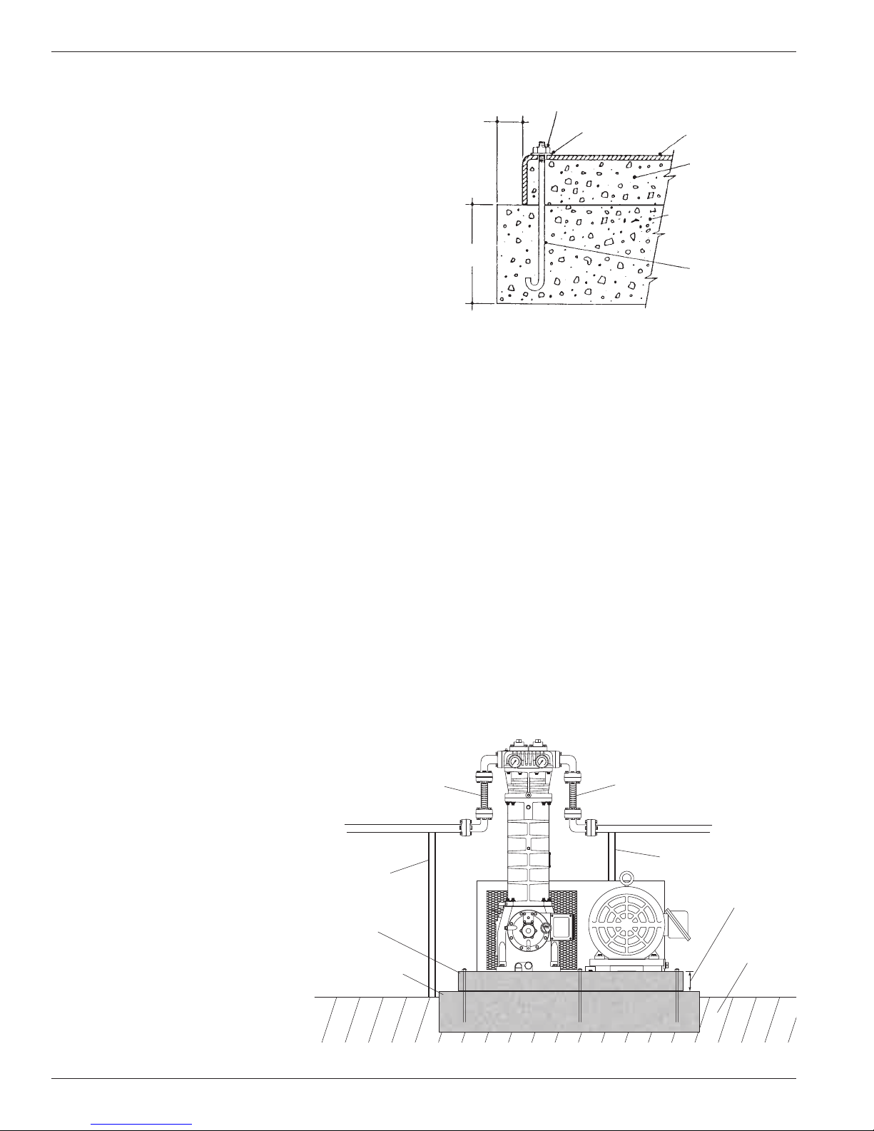
2.2 Foundation
Proper foundations are essential for a smooth running
compression system. Corken recommends the compressor
be attached to a concrete slab at least 8 in. thick with a 2
in. skirt around the circumference of the baseplate. The
baseplate should be securely anchored into the foundation
by 1/2 in. diameter “J” bolts 12 in. long. Four bolts should
be used for models 91, 291, and 491. Six bolts should
be used for model 691. The total mass of the foundation
should be approximately twice the weight of the compressor
system (compressor, baseplate, motor, etc.).
After leveling and bolting down baseplate, the volume
beneath the channel iron baseplate must be grouted
to prevent flexing of the top portion
of the baseplate and the “J” bolt that
extends beyond the foundation. The
grout also improves the dampening
capabilities of the foundation by
creating a solid interface between the
compressor and foundation.
On some of the longer baseplates, such
as with the 691–107, a 3 in. hole can be
cut in the baseplate for filling the middle
section of the baseplate with grout.
See ED410 (Compressor Foundation
Design).
2.3 Piping
Proper piping design and installation
is as important as the foundation is to
smooth operation of the compressor. Improper piping
installation will result in undesirable transmission of
compressor vibration to the piping.
DO NOT SUPPORT PIPING WITH THE COMPRESSOR.
Unsupported piping is the most frequent cause of
vibration of the pipe. The best method to minimize
transmission of vibration from the compressor to the
piping is to use flexible connectors (see figure 2.3A).
Pipe must be adequately sized to prevent excessive pressure
drop between the suction source and the compressor as
well as between the compressor and the final discharge
point. In most cases, piping should be at least the same
diameter as the suction nozzle on the compressor. Typically,
LPG/NH3liquid transfer systems should be designed to
limit pressure drops to 20 psi (1.3 bar). Appendix D shows
recommended pipe sizes for each compressor for typical
LPG/NH3installations.
Figure 2.2A: Recommended Foundation Details
for Corken Compressors 91 - 691
2” MIN.
ALL SIDES
8” MIN.
HEX NUT
WASHER
COMPRESSOR
BASEPLATE
GROUT BENEATH
BASE
CONCRETE FOUNDATION
WITH REINFORCEMENTS
SHOULD BE USED ON ALL
MODELS
1/2” “J” BOLTS
12” LONG
NOTE:
LOCATE “J” BOLTS PER
COMPRESSOR OUTLINE
DIMENSION DRAWINGS.
Ground level
Concrete
foundation
Baseplate should be
a maximum of 4″ high
Grouted
baseplate
Pipe support
Pipe support
Flexible connections Flexible connections
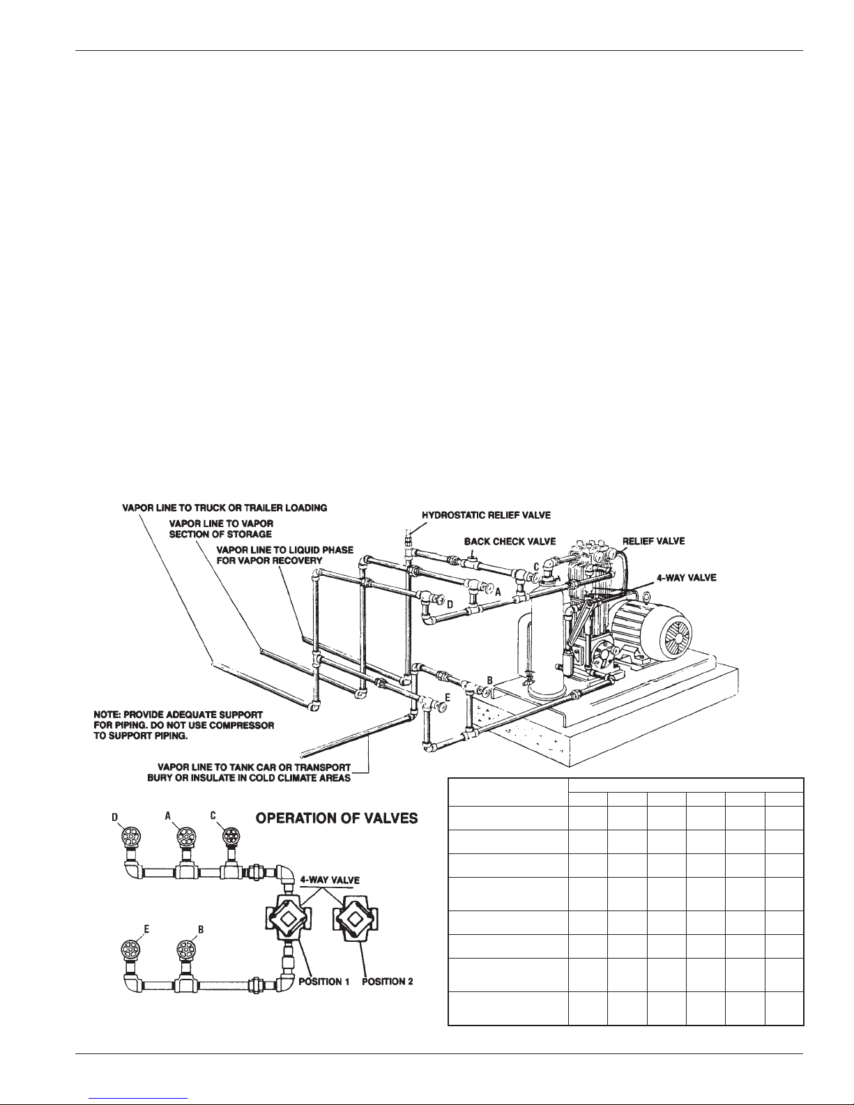
Figure 2.3A: On –107 mountings, the flexible
connectors should be located near the four way valve.
Chapter 2—Installing Your Corken Compressor
8