1.1 Location
NOTE: Corken compressors are designed to handle
toxic or flammable gases and should be located
outdoors in a well ventilated area.
Proper installation of your compressor is essential for
peak performance and reliable service. The installation
area should be clean, well ventilated and have ample
space to install and maintain your compressor. A
double-acting compressor generates more heat than
a typical single-acting compressor. As a result your
compressor should be located in an area where good
air flow and ventilation can be provided. In extreme
cases, external cooling fans can be used to provide
additional air flow across the cylinders. A minimum of
18 inches clearance between the unit and the nearest
wall is advisable. This space will allow access from all
sides and provide unrestricted air flow for adequate
cooling of the motor and compressor. The unit should
be firmly bolted to a solid, level base.
Corken compressors are designed and manufactured
for outdoor duty. For applications where the compressor
will be subjected to extreme conditions such as corrosive
environments or arctic conditions for extended periods
of time, consult Corken.
Check local safety regulations and building codes to
assure installation will meet local safety standards.
Noise:
Corken horizontal compressors should not exceed an 85
DBA noise level when properly installed.
1.2 Foundation
Proper foundations are essential for a smooth running
compression system. The compressor should be
attached to a concrete slab a minimum of 8 inches
thick with a 2 inch skirt around the circumference of
the steel structural skid. The steel structural skid should
be securely anchored into the foundation by 3/4 inch
diameter “J” bolts that are 8 inches long. The total mass
of the concrete foundation should be approximately
twice the weight of the compressor system (i.e. steel
structural skid, compressor, motor, etc.). See figure 1.2
for details.
1.3 Piping
Proper piping design and installation is as important as a
proper foundation is to a smooth operating compressor.
Improper piping installation will result in undesirable
transmission of compressor vibration to the piping. The
compressor piping should be designed for the rate of
flow anticipated and for minimum pressure drop; in no
case should the piping be smaller than the compressor
nozzle to which it connects. If the length of the line must
exceed 100 ft., the next larger size pipe should be used.
Install a strainer at the compressor inlet. Never install
a shut-off valve in the discharge piping unless a safety
relief valve is placed in the line between the shut-off
valve and the compressor. Remember to consider future
expansion in your pipe sizing and layout.
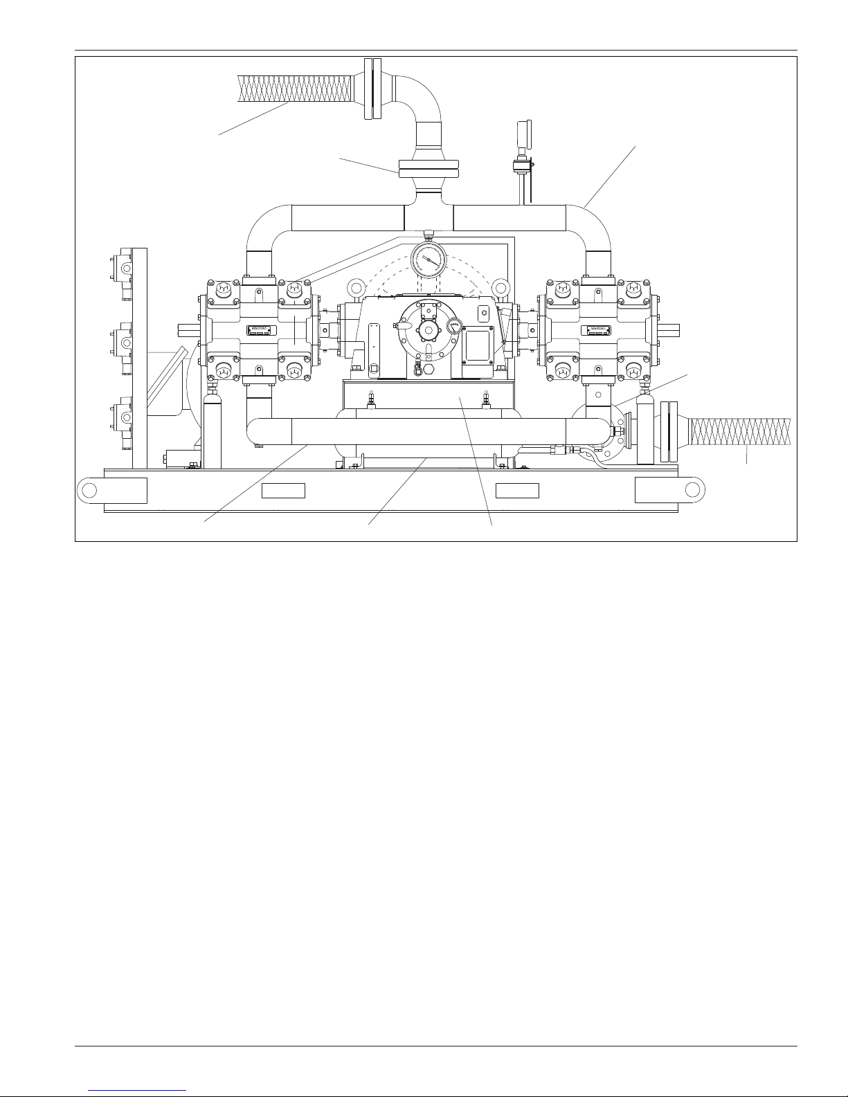
DO NOT SUPPORT PIPING WITH THE COMPRESSOR.
Unsupported piping is the most frequent cause of vibration
of the pipe. The best method to minimize transmission of
vibration from the compressor to the piping is to use
flexible connectors (see figure 1.3 for details).
Pipe must be adequately sized to prevent excessive
pressure drop between the suction source and the
compressor as well as between the compressor and the
final discharge point. In most cases, piping should be
at least the same diameter as the suction nozzle on the
compressor.
If a restrictive device such as a valve, pressure regulator,
or back-check valve is to be installed in the compressor’s
suction line, care must be taken. The suction line volume
between the restrictive device and the compressor
suction nozzle must be at least ten times the swept
cylinder volume.
On liquefied gas applications such as LPG, it is of
extreme importance to prevent the entry of liquid into
the compressor. Installing a liquid trap on the inlet side
will prevent liquid from entering the compressor (see
section 1.4).
Chapter 1—Installation Of Your Compressor
Figure 1.2
Main beam (C-Beam)
Cross beam (H-Beam)
3/4″ diameter “J” bolt
Hex nut
&
washer
Concrete foundation
Note: The depth of the concrete foundation will
vary based on local soil conditions.
6