cormidi 100 Series Guide

This manual should always be readily available so that the machine operator may
consult it immediately, and it must be saved for the entire duration of the machine’s life.
© 2009 - The entire or partial reproduction and/or divulging of this document is prohibited in any form without the written consent of the
manufacturing company. The editing of the text, the illustrations, and the paginations were realized by “Cormidi s.r.l.” The information and
technical data were furnished, checked and validated by the Cormidi Technical Office. The illustrations and technical data included in this
manual are non binding: the manufacturer reserves the right to carry out eventual modifications to its product without notice.
UK
USER’S MANUAL AND MAINTENANCE
series 100
Minitransporter
Ed. 0
CORMIDI
srl
Via Seude Loc. Fonte
84069 Roccadaspide (SA)
0828 943689 Fax 0828 943963
www.cormidi.com info@cormidi.com
leadinginnovation

Series 100
INTRODUCTION
Dear Customer,
We would like to take this opportunity to thank you
for your confidence in us shown by purchasing a
CORMIDI Minitransporter. his product was designed
and constructed for longevity and to be used with
maximum reliability.
It is, however, absolutely necessary to read this
manual carefully in which the procedure for optimum
use of the equipment is described: improper use may
provoke harm to oneself and cause injury to persons
and/or to one’s health.
herefore, always keep this manual within easy
reach so that it may be consulted at any time, before,
during, and after use. If the machine is resold, do not
forget to give it to the new owner in that inside there
is the EC compliance certificate.
We would like to remind you that the illustrations
contained in the manual correspond for the most part
to the base model and that our models are regularly
improved and perfected with the goal of allowing our
customers to enjoy the maximum benefits of
innovations in technology: for this reason the
characteristics and the information contained in the
present manual may have been varied recently. We ask
you to contact us in case you should encounter
difficulty.
Remember for supplementary information you can
always contact your sales representative/dealer, or you
can contact us directly by telephone or by email at
info@cormidi.com
. If there is any doubt, it is better to
ask rather than proceed on your own.
We leave you to your perusal of the manual and
enjoyment of your machine!
Staff CORMIDI Srl

General Information
1
1. GENERAL INFORMATION
1.1. WARRANTY
Your machine is guaranteed for 12 months from the
date of its delivery and includes the substitution of
anything in particular that has resulted as, in the opinion of
our Technical Office, affected by construction defects.
Any part in particular that was not constructed by the
manufacturer, parts used in/on terrain surfaces, and
breakdowns caused by incompetence or carelessness,
including fuelling, are excluded from the guarantee.
The motor, instead, is covered under the manufacturer
of the motor’s own warranty according to the foreseen
conditions and terms.
The guarantee immediately expires if the machine is
utilized for uses different from those foreseen by the
Manufacturer, if it is damaged by the use of unauthorized
accessories or if it is repaired using unsuitable parts.
With the machine a Certificate of Warranty was
supplied which outlines the norms which regulate the
service of assistance under warranty. We highly
recommend reading the warranty form to fully
understand the various rights and responsibilities.
Collaborate with your sales representative when filling out
the form and make sure it is filled out correctly, in that the
text and the other formalities (shipment within the time
limit, etc.) represent the legal base for the warranty on the
machine.
1.2. GOAL OF THE MANUAL
This manual has been drawn up by the
manufacturer and is an integral part of the machine: it
was written in Italian, the native language of the
manufacturer.
The information contained here within is addressed
to expert operators, equipped with specific knowledge
and competence in the sector of use. The manual
defines the objectives for which the machine was
designed and constructed.
To avoid incorrect manoeuvres that risk accident, it
is important to read this manual particularly before the
first use to familiarize oneself with the principal
commands and their functions.
A constant observance of the information

Series 100
2
guarantees safety, economy of use, and a longer
functional duration of the machine.
To give a higher prominence to the sections of the text
which must not be ignored, they have been highlighted in
bold and preceded with symbols illustrated and defined
following here:
READ CAREFULLY:
economy of use, and a
longer functional duration of the machine.
DANGER: indicates imminently
dangerous
situations that can provoke serious injury
or
death if the instructions are not followed.
On the machine potential dangers have
been indicated with a sticker characterized by
a red band with white text.
WARNING: indicates a
potentially
dangerous situation that can provoke
s
erious injury or death if the instructions are
not followed.
On the machine the warnings are indicated
with stickers characterized by an
orange band
with black text.
CAUTION: indicates a potentially
dangerous situation that can p
rovoke injury
or damage to the machine if the instructions
are not followed.
On the machine situations requiring
caution are indicated by sticker
s
characterized by a
yellow band with black text.
PROHIBITED: prohibition
s that must be
observed by all persons who interact directly
and/or indirectly with the machine so that
risks may be limited.
1.3. MACHINE DESCRIPTION
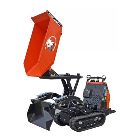
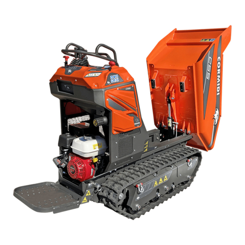
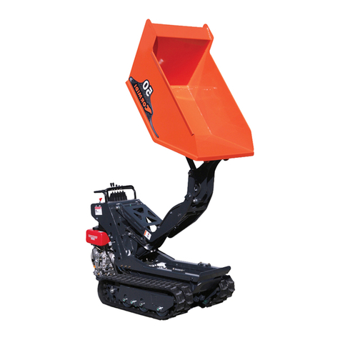
The Series 100 machines are compact auto-
unloading tracked vehicles that are equipped with a
body and sometimes with other auto-loading
equipment, designed and manufactured for the
exclusive use of transporting inert materials.
To satisfy the various requirements of the market,
the machine may be equipped with motors that have
similar power but that have different brand names and
characteristics.

General Information
3
READ CAREFULLY:
Determine the type of
motor that has been installed in your
machine accurately, and read its manual to
familiarize yourself with it.
1.4. SAFETY INFORMATION
READ CAREFULLY:
The information
contained here is essential for your safety and
for that of your co-workers!
During the production of this machine, every possible
measure was taken to make your work safer. Simple
prudence, however, is essential: there is no better rule to
prevent accidents.
WARNING:
The tool must always be operated
by a competent and well-trained operator.
Carefully read the information before using the
machine or before performing maintenance and/or
repairs.
A few minutes of your time spent reading this manual
will save you time and effort later on.
Carefully read the warnings and information written
on the signs on the machine and immediately
substitute missing or illegible ones. Respect all
regulations contained in these.
The machine was made exclusively for the
transportation of inert materials. Any other use is
prohibited.
PROHIBITED: It is strictly prohibited to use
this machine for the transport of persons
and/or animals.
PROHIBITED: It is strictly prohibited to use
this machine to tow other machines
, vehicles,
and/or devices, not even temporarily or in an
emergency situation.
The machine constitutes a work instrument: always
respect the national regulations, especially those
relative to safety at the place of work.
REQUIRED: Always wear suitable work
clothes and above all suitable work shoes
diligently.
Always use protective hearing
devices.
WARNING: Never wear large or fly-
away
clothes (scarves, ties) that could easily get
caught in the moving parts.
It is always advisable to have a first aid kit close at

Series 100
4
hand.
Before turning on the motor, always be sure that
there are not any people, animals, or things that
could be an obstacle in the work area.
DANGER: Never use th
e machine inside
enclosed areas because the gasses emitted
by the exhaust are lethal.
REQUIRED: Carry out the disposal of oils,
minerals, and harmful products with respect
for the environment and in accordance with
the current norms.
Every intervention for cleaning, tuning, and/or
maintenance must be done under good
environmental conditions and with adequate light,
and always with the motor turned off.
DANGER:
Never refuel the vehicle when the
motor i
s on or hot, in the proximity of flames
or while smoking. Always keep the machine
cleaned of lubricant and/or combustible
residues.
Pay careful attention to not come into contact with
the overheated parts of the motor.
P
ROHIBITED: It is strictly prohibited to
remove protection and safety devices with
which the machine is equipped
Avoid working under unsuitable physical conditions
or when you are very tired: in these cases interrupt
your work.
DANGE
R: While working always be sure that
the terrain has the required consistency and
avoid working on the edge of embankments,
ditches, or ravines or on excessively steep or
uneven terrain.
When putting away the machine take all precautions
so that it might not be moved or turned on by
incompetent or incapable persons.
CAUTION: Never leave the machine
unattended while the motor is on, not even
temporarily: when you leave the area, turn off
the motor of the machine and put on the
parking brake!
DANGER: Never let children play with the
machine, not even if it is turned off!

General Information
5
1.5. MACHINE AND MANUFACTURER IDENTIFICATION
The data which identifies the machine and the
manufacturer are listed on the aluminium plate that is
affixed on the dashboard of the machine. The frame
number is stamped on the left of back side.
1 Manufacturer
2 Machine Type
3 Serial Numero
4 Load Capacity KG
5 Machine Mass KG
6 Motor Power KW
7 Fabrication Year
8 EC Brand
0 Frame Number
fig. 1 – Identification Plate (cod. C1094.14.00)
1.6. SAFETY DEVICES
PROHIBITED: it is strictly prohibited to use
the machine with its safety devices and
protection removed, blocked, or in any way
made non functional.
WARNING: Before beg
inning work, verify the
working order of the safety devices and
substitute any worn-
out and/or broken parts
immediately.
1.6.1. BLOCKING THE BODY
The machine is equipped with a device to block the
body in the raised position and to prevent it from lowering
accidentally.
Before carrying out any repair maintenance work with
the body raised, always block the piston following this
procedure (see fig. 2):
•raise the body;
•turn off the motor;
•remove device “A” from its slot by unscrewing wheel
“B”;
•insert the hole of the bar on the piston of the hydraulic
jack;
•Turn the bar and position it so that it is parallel to the

Series 100
6
piston;
•slowly lower the unit with the motor off until the
correct fit of the device is obtained.
Afterwards remove the device and put it back in its slot.
1.6.2. BLOCKING THE FOOTREST
The drive footrest must always be blocked in position
to impede its accidental movement, by using the safety pin
“B” (see fig.2).
Introduce pin “B” into hole “1” to block the footrest in the
raised position;
Introduce pin “B” in hole “2” to block the footrest in the
lowered position;
fig. 2 – Safety Devices
1.7. ACCESSORIES
READ CAREFULLY: Read the
instructions
and the mode of use for the accessories that
have been installed on your machine carefully.
Refer to the instruction manual that was
provided with them.
The machine is furnished with equippment to make it

General Information
7
possible to carry out normal maintenance operations.
It is also equipped with a hydraulic force instrument: in
the manual the instructions for its use have been
furnished.
Also, the machine the may also be equipped upon
request with particular tools including:
•Cement mixer for mixing concrete;
•Auto-loading tools;
•Excavator;
•Demolition hammer.
1.8. SAFETY TAGS
READ CAREFULLY: During the design phase
everything possible was done to prevent
eventual risks: where it was tec
hnically
impossible, specific pictograms were resorted
to in order to highlight
eventual potential and
imminent risks.
Specific adhesive tags were made with
signals and descriptions associated with
pictograms to give a higher importance to
possible danger
s, in accordance with
government norms UNI 9244-95 (E).
PROHIBITED: it is strictly prohibited to
remove the stickers and the safety plates
which the machine is equipped with:
immediately substitute deteriorated and/or
illegible ones.
fig. 3 – Position of the safety tags

Series 100
8
1.8.1. SAFETY DISTANCE
Tag which alerts the serious
danger of coming near and
standing within the field of action
of the machine in that there is an
imminent risk of danger.
1.8.2. HOT SURFACE
Invites caution in that there is a
risk of burning because of the
nearness to the hot surface.
1.8.3. FAN
Indicates
a potential risk of danger in that
there is a possibility of coming into
contact with moving mechanical
parts that can cause serious injury.
1.8.4. CRUSHING
Tags which indicate a potential
risk of crushing that may cause very
serious injury or death.
1.8.5. CUTTING
Tags which indicate a potential
risk of cutting that may cause very
serious injury or death.
1.8.6. PROCEDURE FOR CAUTION
This adhesive
which invites caution
reminds one to adopt
all anti-injury precau-
tions, above all
regarding the use of
protective devices and
individual prevention.
The meaning of the
fig. 4 (cod. C1094.02.00)
fig. 5 (cod. C1094.07.00)
fig. 6 (cod. C1094.08.00)
fig. 7 (cod. C1094.09.00)
fig. 9 (cod. C1094.04.00)
fig. 8 (cod. C1094.09.00)

General Information
9
pictograms is the following:
•Read the manual before turning the machine on for the
first time, each time an operator is changed, and in any
case in which doubt is raised as to how the machine
functions;
•Wear a headset which protects hearing or another
device of this type;
•Wear protective gloves of the prescribed type;
•Wear injury-preventive shoes of the prescribed type.
1.8.7. OVERTURNING
Indicates an imminent risk of
overturning with serious
consequences during use of the
high unloading.
The correct procedure to carry
out high unloading includes the
necessity to rest the shovel of the
auto-loading on the ground in a
way that stabilizes the machine
before raising the body and
unloading.
Instead the upper part of the tag indicates the incorrect
procedure which must be avoided absolutely, while the
lower part shows the correct position to carry out the
unloading safely.
1.8.8. MAXIMUM SLOPES
Completely avoid working on
terrains that have latitudinal slopes
of more than 10° and longitudinal
slopes of more than 20°to avoid the
possibility of overturning with
serious consequences for the safety
of the operator. In every case, but
especially in the case of slopes, it is
important that the terrain is solid and
stable.
1.8.9. PROCEDURE FOR ADDRESSING SLOPES
Sign which indicates in what way
one must address the downhill and
uphill slopes to avoid serious
consequences for the operator and
for the machine in that there is the
potential danger of overturning.
fig. 11 (cod. C1094.01.00)
fig. 10 (cod. C1094.10.00)
fig. 12 (cod. C1094.06.00)

Series 100
10
1.9. ADMISSIBLE SLOPES
fig. 13 – Maximum admissible slopes
In figure 13 the maximum values for the latitudinal and
longitudinal slopes of the terrain are shown on which it is
possible to work. These conditions must never be
surpassed to avoid the risk of overturning.
DANGER: Always avoid working on terrain
with slopes that are greater than those
prescribed to avoid the po
ssibility of
overturning with possible serious
consequences for the safety of the operator..
In every case, but especially when working on slopes,
it is important that the terrain is solid and stable.
1.10. DIMENSIONS
Normal Auto-loading 3S
Length 1930 mm 2580 mm 1930 mm
Width 950 mm 950 mm 1050 mm
Wheel Track 755 mm 755 mm 755 mm
Min 1350 mm 1350 mm 1350 mm
Height Max 1595 mm 2000 mm 1650 mm
fig. 14 – Dimensions

General Information
11
1.11. TECHNICAL DATA
Model Dumper Self-loading 3S
Type 14.100 18.100 14.100 18.100 14.100 18.100
Mass [kg] 580 635 695 750 630 685
Power [kW] 9,6 13,2 9,6 13,2 9,6 13,2
Max Speed [km/h] - (m/s) 5,2 (1,4) 6,5 (1,8) 5,2 (1,4) 6,5 (1,8) 5,2 (1,4) 6,5 (1,8)
Load Capacity [kg] 1000 1000 1000
Start-up Electric
Accelerator Manual command lever
Trasmission Hydrostatic
Parking Brake Automatic
Battery 12V - 40Ah with negative at ground
Tipo 14.100 18.100
Continuous Equivalent Pondered Acoustic Power Level A LpA =
100 dB(A) 100 dB(A)
Continuous Equivalent Pondered Acoustic Power Level A
(assured) LwA =
101 dB(A) 101 dB(A)
Vibrations Level m/s² on arms: ≤2,5 m/s²
on body: ≤0,5 m/s²

Series 100
12
2. COMMANDS
Attention,the configuration of the machine’s controls may vary from the configuration described
here, according to version.
2.1. HYDRAULIC OVERTURNING VERSION
Horn Command
The horn button is on the left side of the
instrument panel. To sound the horn, push the
button. Only intermittent mode horn operation is
enabled. Continuous mode is not enabled.
fig. 15 – Horn Command
Accelerator Command
STABLE POSITION
Minimum regimen
…
STABLE POSITION
Intermediate regimens
STABLE POSITION
Maximum regimen
Allows you to vary the motor rotation regimen,
so that you may obtain the required power.
fig. 16 – Accelerator Command

Commands
13
Drive Levers
The command levers control the rotation of the tracks through a hydraulic feed of the hydraulic motors.
The command levers are active only when the motor is turned on.
The left Drive Lever
UNSTABLE POSITION
The left track rotates forward
STABLE POSITION
Resting position
UNSTABLE POSITION
The left track rotates backwards
The left-hand drive lever controls the left track.
fig. 17 – Command lever for the left
track
The right Drive Lever
UNSTABLE POSITION
The right track rotates forward
STABLE POSITION
Resting position
UNSTABLE POSITION
The right track rotates
backwards
The right-hand drive lever controls the right
track.
fig. 18
Command lever for the right track

Series 100
14
Command Lever for the Hydraulic Take-off
Instrument
UNSTABLE POSITION
Hydraulic pressure on “A”
STABLE POSITION
Resting position
POSIZIONE INSTABILE
Hydraulic pressure on “B”
The hydraulic take-off instrument is composed
of two openings with rapid transmission of standard
type, indicated by the letters “A” and “B”, situated
on the right side of the dashboard.
The auxiliary command lever allows you to put
hydraulic oil pressure on the openings.
fig. 19
Command lever for the hydraulic force
instrument
Command Lever for the Body
UNSTABLE POSITION
The body overturns
STABLE POSITION
Resting position
UNSTABLE POSITION
Resting position
The command lever for the body activates the
hydraulic jack that activates the tipping of the body.
This position can only be used with the motor
turned on, while this position can also be used
when the motor is turned off.
fig. 20
Command lever for the body

Commands
15
2.2. AUTOLOADING VERSION
Horn Command
The horn button is on the left side of the
instrument panel. To sound the horn, push the
button. Only intermittent mode horn operation is
enabled. Continuous mode is not enabled.
fig. 21
Horn Command
Accelerator Command
POSIZIONE STABILE
Minimum regimen
…
POSIZIONE STABILE
Intermediate regimen
POSIZIONE STABILE
Maximum regimen
The command lever for the accelerator acts
upon the motor and allows one to vary the rotation
regimen in order to obtain the required power.
fig. 22
Accelerator Command

Series 100
16
Drive Levers
The drive levers control the rotation of the tracks through a hydraulic feed to the hydraulic motors.
The levers are active only when the motor is turned on.
Left Drive Lever
UNSTABLE POSITION
The left track rotates forward
STABLEPOSITION
Resting position
UNSTABLE POSITION
The left track rotates backward
The left lever controls the left track.
fig. 23
Left track command lever
Right drive lever
UNSTABLE POSITION
The right track rotates forward
STABLE POSITION
Resting position
UNSTABLE POSITION
The left track rotates backward
The right lever controls the right track.
fig. 24
Right track command lever

Commands
17
Command Lever for the Hydraulic Take-off
Openings
UNSTABLE POSITION
Hydraulic pressure on “A”
STABLE POSITION
Resting position
UNSTABLE POSITION
Hydraulic pressure on “B”
The hydraulic take-off instrument is composed
of two openings with rapid transmission of standard
type, indicated by the letters “A” and “B”, situated
on the right side of the dashboard.
The auxiliary command lever allows you to
apply hydraulic oil pressure on the openings.
fig. 25
Command lever for the Hydraulic
Power Take-Off Openings
Command Lever for the Body
UNSTABLE POSITION
The body overturns
STABLE POSITION
Resting position
UNSTABLE POSITION
The body lowers
The command lever for the body activates the
hydraulic jack that activates the tipping of the body.
This position can only be used with the motor
turned on, while this position can also be used
when the motor is turned off.
fig. 26
Command lever for the body

Series 100
18
Auto-loading Command Lever
STABLE POSITION
The bucket is free (floating)
UNSTABLE POSITION
Lowering of the bucket
STABLE POSITION
Resting position
UNSTABLE POSITION
Raising of the bucket
The command lever for the auto-loading tool
works the hydraulic levers that provoke the raising
of the auto-loading bucket.
This command may only be used when the
motor is turned on.
fig. 27
Command lever for the body
This manual suits for next models
3
Table of contents
Other cormidi Farm Equipment manuals